EP0016888A1 - Biocidal gas sterilization method and apparatus - Google Patents
Biocidal gas sterilization method and apparatus Download PDFInfo
- Publication number
- EP0016888A1 EP0016888A1 EP79303051A EP79303051A EP0016888A1 EP 0016888 A1 EP0016888 A1 EP 0016888A1 EP 79303051 A EP79303051 A EP 79303051A EP 79303051 A EP79303051 A EP 79303051A EP 0016888 A1 EP0016888 A1 EP 0016888A1
- Authority
- EP
- European Patent Office
- Prior art keywords
- biocidal gas
- chamber
- gas
- biocidal
- make
- Prior art date
- Legal status (The legal status is an assumption and is not a legal conclusion. Google has not performed a legal analysis and makes no representation as to the accuracy of the status listed.)
- Ceased
Links
- 230000003115 biocidal effect Effects 0.000 title claims abstract description 81
- 230000001954 sterilising effect Effects 0.000 title claims abstract description 65
- 238000000034 method Methods 0.000 title claims abstract description 21
- 238000004659 sterilization and disinfection Methods 0.000 title claims description 23
- 238000010521 absorption reaction Methods 0.000 claims abstract description 48
- 230000003750 conditioning effect Effects 0.000 claims abstract description 26
- 238000012544 monitoring process Methods 0.000 claims abstract description 10
- IAYPIBMASNFSPL-UHFFFAOYSA-N Ethylene oxide Chemical compound C1CO1 IAYPIBMASNFSPL-UHFFFAOYSA-N 0.000 claims description 35
- 238000007789 sealing Methods 0.000 claims description 8
- 230000007423 decrease Effects 0.000 claims description 6
- 230000001143 conditioned effect Effects 0.000 claims description 2
- 239000003112 inhibitor Substances 0.000 claims 1
- 238000005259 measurement Methods 0.000 claims 1
- 230000011664 signaling Effects 0.000 claims 1
- 239000007789 gas Substances 0.000 description 87
- 238000011156 evaluation Methods 0.000 description 8
- 239000000463 material Substances 0.000 description 5
- 238000010793 Steam injection (oil industry) Methods 0.000 description 4
- 230000001419 dependent effect Effects 0.000 description 3
- 238000010586 diagram Methods 0.000 description 3
- 230000006835 compression Effects 0.000 description 2
- 238000007906 compression Methods 0.000 description 2
- 239000004744 fabric Substances 0.000 description 2
- 230000000977 initiatory effect Effects 0.000 description 2
- 239000000203 mixture Substances 0.000 description 2
- 230000000007 visual effect Effects 0.000 description 2
- CPELXLSAUQHCOX-UHFFFAOYSA-M Bromide Chemical compound [Br-] CPELXLSAUQHCOX-UHFFFAOYSA-M 0.000 description 1
- 206010015946 Eye irritation Diseases 0.000 description 1
- 206010040880 Skin irritation Diseases 0.000 description 1
- 229940100198 alkylating agent Drugs 0.000 description 1
- 239000002168 alkylating agent Substances 0.000 description 1
- 230000033228 biological regulation Effects 0.000 description 1
- 230000000711 cancerogenic effect Effects 0.000 description 1
- 238000006243 chemical reaction Methods 0.000 description 1
- 230000001276 controlling effect Effects 0.000 description 1
- 125000004122 cyclic group Chemical group 0.000 description 1
- 230000003247 decreasing effect Effects 0.000 description 1
- 239000003085 diluting agent Substances 0.000 description 1
- 230000000694 effects Effects 0.000 description 1
- 231100000013 eye irritation Toxicity 0.000 description 1
- 230000002401 inhibitory effect Effects 0.000 description 1
- 238000002347 injection Methods 0.000 description 1
- 239000007924 injection Substances 0.000 description 1
- 239000002184 metal Substances 0.000 description 1
- 244000005700 microbiome Species 0.000 description 1
- 102000004169 proteins and genes Human genes 0.000 description 1
- 108090000623 proteins and genes Proteins 0.000 description 1
- 230000001105 regulatory effect Effects 0.000 description 1
- 238000012163 sequencing technique Methods 0.000 description 1
- 230000036556 skin irritation Effects 0.000 description 1
- 231100000475 skin irritation Toxicity 0.000 description 1
- 239000000126 substance Substances 0.000 description 1
- 230000000153 supplemental effect Effects 0.000 description 1
Images

Classifications
-
- A—HUMAN NECESSITIES
- A61—MEDICAL OR VETERINARY SCIENCE; HYGIENE
- A61L—METHODS OR APPARATUS FOR STERILISING MATERIALS OR OBJECTS IN GENERAL; DISINFECTION, STERILISATION OR DEODORISATION OF AIR; CHEMICAL ASPECTS OF BANDAGES, DRESSINGS, ABSORBENT PADS OR SURGICAL ARTICLES; MATERIALS FOR BANDAGES, DRESSINGS, ABSORBENT PADS OR SURGICAL ARTICLES
- A61L2/00—Methods or apparatus for disinfecting or sterilising materials or objects other than foodstuffs or contact lenses; Accessories therefor
- A61L2/24—Apparatus using programmed or automatic operation
-
- A—HUMAN NECESSITIES
- A61—MEDICAL OR VETERINARY SCIENCE; HYGIENE
- A61L—METHODS OR APPARATUS FOR STERILISING MATERIALS OR OBJECTS IN GENERAL; DISINFECTION, STERILISATION OR DEODORISATION OF AIR; CHEMICAL ASPECTS OF BANDAGES, DRESSINGS, ABSORBENT PADS OR SURGICAL ARTICLES; MATERIALS FOR BANDAGES, DRESSINGS, ABSORBENT PADS OR SURGICAL ARTICLES
- A61L2/00—Methods or apparatus for disinfecting or sterilising materials or objects other than foodstuffs or contact lenses; Accessories therefor
- A61L2/16—Methods or apparatus for disinfecting or sterilising materials or objects other than foodstuffs or contact lenses; Accessories therefor using chemical substances
- A61L2/20—Gaseous substances, e.g. vapours
- A61L2/206—Ethylene oxide
Definitions
- This invention is concerned with biocidal gas sterilization methods and apparatus.
- ETO Ethylene oxide
- One object of the present invention is an early determination of unacceptable biocidal gas leakage from a sterilizing chamber during a sterilizing cycle.
- Pressure vessels to be used as sterilizing chambers are manufactured to prescribed tolerances, e.g. about 267 Pa (two mm Hg) per minute leakage rate, and tested before being put into use in biocidal gas sterilizing operations.
- sterilizing chambers are sealed for operating at pressure other than atmospheric.
- the largest sealing zone surrounds the sterilizing chamber door which provides access for loading the chamber with goods to be sterilized.
- Such closures are sealed by compression of gasket material; or, often, such gasket material is pneunatically inflated or pneumatically moved into sealing relationship with a closure sealing surface on the sterilizer.
- Such gasket materials are subject to wear and fatigue with usage and become one of the most prevalent sources of harmful leakage.
- Other causes of gas leakage into the environment of the sterilizer can include check valves, compression tubing fittings, and other valving arrangements on supply and exhaust piping to the chamber shell where such valving arrangements help define the chamber volume subject to biocidal gas pressure.
- Vacuum conditions within a chamber generally aid sealing of worn or faulty gasket material so that a determination of harmful leakage of biocidal gas, to be timely and meaningful ought to be available when the chamber is under biocidal gas pressure. And, the determination should be available early after establishment of biocidal gas pressure and, also, throughout the sterilizing phase.
- the present invention resides in a gas sterilization process utilizing a biocidal gas, such as ethylene oxide, in which a sterilizing chamber is charged with biocidal gas to a desired concentration after the sterilizing chamber has been loaded with goods to be sterilized and.hasbeen sealed for operation at pressures other than atmospheric, characterized in that make-up charging of biocidal gas, required to maintain such biocidal gas concentration for an extended time period to complete the desired sterilization, is monitored to deternine unacceptable biocidal gas leakage from the chamber.
- a biocidal gas such as ethylene oxide
- the invention includes biocidal gas sterilizing apparatus having a sterilizing chamber with a closure for sealing such chamber for operation above atmospheric pressure, and means for charging a biocidal gas at pressures above atmospheric into the chamber, characterised by a sensor for sensing biocidal gas concentration in the chamber, make-up charging of biocidal gas into the chamber being effected responsively to the sensor to maintain a desired biocidal gas concentration in the chamber for a preselected sterilizing phase time to complete desired sterilization, and by a control device for quantitatively monitoring the need for make-up charging of biocidal gas into the chamber to determine unacceptable biocidal gas leakage from the container.
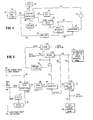
- a chamber 10 is defined by a shell having a side wall 12 and rear wall 14, and by an access door 16. After loading the chamber with goods to be sterilized, the door 16 is closed and sealed for operation at pressures other than atmospheric. Gasket 18 provides for sealing of the door where contact is made with the chamber shell.
- the volume subject to pressures other than atmospheric can include portions of conduits leading to and from the chamber dependent on piping and various locations for check valves 20 and 22.
- chamber 10 is generally subjected to an initial evacuation by opening valve 24 in conduit 26 connecting vacuum source 28 to the chamber 10.
- This initial evacuation can extend from atmospheric pressure level at point 30 to approximately 8 x 10 3 Pa (sixty mm-Hg) at point 32.
- a conditioning vapour such as steam
- Conditioning of the load can include repressurization as indicated by line 34 of Figure 2, between a lower subatmospheric pressure at point 32 and an upper subatmospheric pressure at point 36.
- the initial evacuation along evacuation line 31 of Figure 2 and repressurization along line 34 can be controlled with pressure switches forming part of pressure sensor 40 of Figure 1.
- sensor 42 can comprise a relative humidity gauge which will control conditioning steam addition to hold chamber relati humidity at a desired level; or, in other commercially known conditioning phases, sensor 42 can be temperature sensitive and located near the drain line to control steam flow through the chamber to heat the load by steam flow.
- pressure signals over line 44 to control 46 provide proper sequencing; e.g. a signal over line 48 to solenoid 50 (Figure 1) terminates initial evacuation when a desired subatmospheric pressure, such as 8 x 10 3 Pa, is reached at point 32 ( Figure 2).
- a signal from control 46 on line 54 to solenoid 56 opens steam valve 58.
- Steam from source 60 flows through conduit 62 into chamber 10 and raises the pressure within the chamber as indicated by repressurization line 34. Cyclic evacuation and steam injection can be carried out during the conditioning phase of the sterilizing cycle between point 36 and point 64 to raise the temperature and moisten the goods to be sterilized to desired levels.
- a biocidal gas is charged along gas pressurization line 66 ( Figure 2) from a subatmospheric level at point 64 to a pressure above atmospheric level at point 68.
- biocidal gas charge can be controlled by a high pressure switch forming part of pressure sensor 40 which sends a signal along line 44 to control 46. From control 46, a signal in line 70 to solenoid 72 controls valve 74 which permits biocidal gas to flow from source 76 through conduit 78 to conduit 80 an through check valve 20 into chamber 10. Evacuation valve 24 is closed during such gas charge and during the sterilizing phase of the cycle between points 68 and 82 of the cycle graph of Figure 2.
- sterilization with ET0 is based on an integrated effect of load temperature and moisture, ETO concentration, and time.
- load temperature at about 54°C (130 0 F)
- sterilization with an adequate safety factor can be carried out in less than two hours.
- sterilization time is increased and at higher temperatures sterilization time is decreased.
- a biocidal gas comprising ETO includes 'about 12% ET0 and about 88% of a diluent, such as freon.
- a chamber pressure of about 55 x 10 3 Pa gauge (8 psig) provides an ETO concentration of about 650 mg/l.
- Other pressure levels can be selected for varying concentrations or other ETO mixtures.
- a gas pressure from about 35 x 10 3 Pa gauge to about 103 x 10 3 Pa gauge (five psig to fifteen psig) and higher, would be used.
- the pressure selected e.g. 55 x 10 3 Pa gauge is maintained during the sterilization phase by controlling gas valve 74 through control 46. If a preselected pressure decrement (e.g. about 3.5 x 10 3 Pa) occurs, a make-up charge of biocidal gas is introduced during the sterilizing phase to hold desired pressure level and, in turn, ETO concentration. Within prescribed tolerances, a make-up charge based on a pressure drop of about 3.5 x 10 3 Pa should not occur in less than a prescribed interval of about fifteen minutes. The make-up charge values for biocidal gas are monitored to determine whether an unacceptable ET0 leakage rate exists.
- a preselected pressure decrement e.g. about 3.5 x 10 3 Pa
- a call for supplemental ETO in less than a prescribed interval indicates unacceptable gas loss.
- the slope of the pressure curve 92 can be compared with the accepted slope (pressure decrease vs. time) value in quantitatively monitoring make-up charging rate of biocidal gas to determine gas leakage.
- gas charge along line 66 of Figure 2 is dependent on the flow rate of ETO and chamber size; gas charge can take from a few minutes to fifteen minutes, or more.
- an initial make-up charge of biocidal gas may be called for in a short interval due to absorption of the biocidal gas by the goods to be sterilized.
- load-absorption decrease in chamber pressure along line 84 will be dependent upon such factors as load characteristics and volumetric relationship of the load, chamber, and gas charge.
- a soft goods load e.g.
- Parameters for such a load-absorption repressurization with ETO biocidal gas are pre-established or calculated.
- compensating for load absorption can have more relevance and significance when working with large volume industrial sterilizers than the smaller hospital units.
- a major portion of initial load absorption can take place during the gas charge.
- the load absorption charge required can be ascertained empirically for differing loads and the time increment and pressure decrement values for an average load established.
- the initial load absorption can be compensated for directly with these values or the slope of the load-absorption curve can be established and utilized in analyzing make-up charging rate.
- a time value along the horizontal component of line 92 and, a pressure increment along line 94 are established for a make-up charge within accepted tolerances; e.g. a 3.5 x 10 3 Pa make-up over a time interval of fifteen minutes, or more, could be considered within accepted tolerances for a particular sterilizer.
- the time of line 92 would be started at point 68 to provide early determination of harmful biocidal gas leakage. If a make-up charge is called for in any lesser time than the accepted interval, e.g. at point 95 of Figure 2, this determines that an unacceptable ETO leak rate exists and, addition of biocidal gas is interrupted. Also, the sterilizing phase can be terminated and sterilizing gas exhausted from the chamber based on such determination of an unacceptable ETO leakage rate, or, the entire cycle can be aborted.
- Load absorption characteristics can be evaluated and predicted more readily with conditioning methods which exhibit a repressurization curve, as represented by line 34 of Figure 2.
- a functional relationship exists between the time required for conditioning vapour pulsing phases and the percentage of soft goods in the load which provides an indication of load characteristics.
- the load characteristic evaluation available during conditioning can be used to predict biocidal gas load absorption and what the slope load absorption line 84 should be in sterilizers where load absorption is a significant factor.
- an earlier or preliminary indication of unacceptable ETO gas leakage can be made.based on the predicated slope of line 84.
- Such preliminary indication can be accomplished when a make-up charge is called for in a shorter time interval than that predicated based on load characteristics or by analyzing the slope of the pressure decrease line 84; a steeper slope than predicted would indicate unacceptable leakage.
- the steps upon this determination can be as previously enumerated, i.e. stopping gas charge, providing a visual or audible warning, and/or exhausting the chamber of sterilizing gas and/or aborting the entire cycle.
- the sterilization phase can proceed along line 98 to complete desired sterilization; and, then, to exhaust the chamber as represented by exhaust line 99. Monitoring gas make-up continues, however, throughout the sterilization to determine if any leaks occur at any part of that phase.
- signal generator 102 delivers a signal along line 104 to sequence controller 106.
- the conditioning phase can be pressure responsive.
- Pressure sensor 108 directs signals over line 110 to the sequence controller 106.
- the chamber is exposed to vacuum source 112 by a signal on line 114 and steam is injected from source 116 by a signal on line 118.
- the pressure sensor 108 can include pressure switches responsive to subatnospheric chamber pressures encountered during conditioning; for example at 8 x 10 3 Pa, to stop evacuating and start steam injection; then, at 12 x 10 3 Pa, to stop steam injection and start evacuation. Such pressure responsive pulsing continues until desired conditioning is completed.
- sequence controller 106 initiates gas charge from source 120 by a signal on line 122.
- sterilization phase'timer 124 provides for holding biocidal gas pressure for the selected sterilization time responsive to pressure sensor 108.
- Chamber gas pressure can be recorded vs. time on recorder chart 126 responsive to signals on lines 128 and 130 while the desired chamber gas pressure is held via pressure signals to sequence controller 106 for the selected sterilization time.
- make-up charges of biocidal gas are compared with predetermined parameters of pressure increment and time, as previously described, in comparator 132.
- a determination of ETO leakage generates a signal on line 134 to warning indicator 135 and to sequence controller 106 to interrupt gas injection and/or abort the cycle and exhaust the chamber.
- a predicated ETO absorption rate can be compared with the actual gas absorption make-up charge curve 84 in comparator 132.
- Figure 4 shows a block schematic circuit diagram of components for monitoring gas make-up charging rate and carrying out control electronically.
- time increment and pressure decrement values for an acceptable gas. make-up charging rate are established, e.g. about 3.5 x 10 3 Pa in fifteen or more minutes
- a determination of ETO leakage is made responsive to a make-up requirement occurring in less than the established time interval, for which only a portion of the circuitry shown schematically in Figure 4 is utilized.
- a selected gas pressure such as 55 x 10 3 Pa gauge
- pressure sensor element 138 puts a signal on line 139 to interrupt gas charge and start timer 140 which is preset for the established time interval, e.g. fifteen minutes.
- a signal is sent over line 142 and over line 143 to timer 140 which, in turn, sends a signal to comparator 144 over line 145.
- the comparator 144 is activated by a signal over line 146.
- no signal is sent on line 148 to activate inhibit means 150 and the signal on line 142 causes a signal on line 152 to open the gas valve for acceptable gas make-up.
- a signal from comparator 144 to inhibit means 150 prevents opening of the gas valve and a signal on line 154 activates a visible or audible alarm 155 and can initiate the other termination procedures described above.
- An operator override at 156 can permit operator evaluation before initiating cycle termination procedures.
- conditioning phase values can be used to predict expected gas absorption. For example, the repressurization time between a lower and upper subatmospheric pressure during conditioning, as previously described, can be used to indicate'steam absorption characteristics.
- a signal at input terminal 160 starts, or resets, the control.
- a conditioning phase low pressure, e.g. 8 x 10 3 Pa (60 torr.), signal is delivered to input terminal 162 and, unless inhibited, sends a signal over line 164 to timer 166.
- the conditioning phase upper pressure, e.g. 12 x 10 3 Pa (90 torr.) value is introduced at input terminal 168 and delivered to timer 166 on line 170.
- Latch 172 inhibits initiation of the timer 166 until the proper steam pulsing time in the conditioning phase, e.g. inhibiting signals during the initial evacuation of the chamber.
- Previously described make-up charging apparatus through timer 140, sends a signal representative of the actual make-up charge time.
- Comparator 144 functions as described earlier; if a make-up charge is called for in a shorter time interval than predicted, an unacceptable leakage is indicated and evaluation or termination procedures are undertaken.
- the slope of the predicted gas absorption curve can be compared with that of the actual gas absorption curve to make a determination along line 84 whether unacceptable ETO leakage is occurring.
Landscapes
- Health & Medical Sciences (AREA)
- Epidemiology (AREA)
- Life Sciences & Earth Sciences (AREA)
- Animal Behavior & Ethology (AREA)
- General Health & Medical Sciences (AREA)
- Public Health (AREA)
- Veterinary Medicine (AREA)
- Chemical & Material Sciences (AREA)
- Chemical Kinetics & Catalysis (AREA)
- General Chemical & Material Sciences (AREA)
- Apparatus For Disinfection Or Sterilisation (AREA)
Applications Claiming Priority (2)
| Application Number | Priority Date | Filing Date | Title |
|---|---|---|---|
| US9817 | 1979-02-06 | ||
| US06/009,817 US4457892A (en) | 1979-02-06 | 1979-02-06 | Biocidal gas sterilization and gas leakage determination |
Publications (1)
| Publication Number | Publication Date |
|---|---|
| EP0016888A1 true EP0016888A1 (en) | 1980-10-15 |
Family
ID=21739876
Family Applications (1)
| Application Number | Title | Priority Date | Filing Date |
|---|---|---|---|
| EP79303051A Ceased EP0016888A1 (en) | 1979-02-06 | 1979-12-24 | Biocidal gas sterilization method and apparatus |
Country Status (8)
| Country | Link |
|---|---|
| US (1) | US4457892A (enExample) |
| EP (1) | EP0016888A1 (enExample) |
| JP (1) | JPS55103860A (enExample) |
| AU (1) | AU529340B2 (enExample) |
| CA (1) | CA1135469A (enExample) |
| ES (1) | ES8102808A1 (enExample) |
| NZ (1) | NZ192272A (enExample) |
| PT (1) | PT70636A (enExample) |
Cited By (3)
| Publication number | Priority date | Publication date | Assignee | Title |
|---|---|---|---|---|
| EP0077831A4 (en) * | 1981-05-07 | 1983-09-02 | Mdt Chemical Company | COMBINED UNSATURATED STEAM AND CHEMICAL STEAM STERILIZER. |
| EP1166802A3 (en) * | 2000-06-27 | 2003-05-02 | Ethicon, Inc. | Method for rapidly determining the acceptability of loads to be sterilized |
| EP3084660A4 (en) * | 2013-12-16 | 2017-08-23 | 3M Innovative Properties Company | Systems and methods for controlling humidity |
Families Citing this family (22)
| Publication number | Priority date | Publication date | Assignee | Title |
|---|---|---|---|---|
| US4759909A (en) * | 1983-02-23 | 1988-07-26 | Joslyn Valve Corp. | Methods and apparatus for steam sterilization |
| CA1271309A (en) * | 1985-02-05 | 1990-07-10 | Raymond P. Jefferis Iii | Gas sterilant system |
| US4908188A (en) * | 1985-02-05 | 1990-03-13 | The Scopas Technology Company, Inc. | Gas sterilant system |
| US4752445A (en) * | 1985-08-20 | 1988-06-21 | American Sterilizer Company | Bi-directional sealing method to control fluid flow between an air inlet and a pressure chamber |
| US4923681A (en) * | 1986-10-03 | 1990-05-08 | Archeraire Industries, Inc. | High velocity hot air sterilization device with controller |
| US4921675A (en) * | 1987-04-28 | 1990-05-01 | Mdt Corporation | Biocidal gas sterilizer |
| DE3736375C1 (en) * | 1987-10-27 | 1989-02-02 | Muenchner Medizin Mechanik | Method of checking a gas steriliser for leaks and gas steriliser for performing the method |
| US5022898A (en) * | 1990-01-11 | 1991-06-11 | Mdt Corporation | Exhaust filter system for sterilizers |
| US6105435A (en) * | 1997-10-24 | 2000-08-22 | Cypress Semiconductor Corp. | Circuit and apparatus for verifying a chamber seal, and method of depositing a material onto a substrate using the same |
| GB9723595D0 (en) * | 1997-11-08 | 1998-01-07 | Smiths Industries Plc | Autoclaves |
| EP1600171B1 (en) * | 1998-10-05 | 2017-08-02 | W & H Sterilization S.r.l. | Autoclave |
| DE19908035B4 (de) * | 1999-02-24 | 2006-03-23 | Khs Maschinen- Und Anlagenbau Ag | Verfahren zum Betreiben einer Pasteurisierungsanlage |
| US6834473B2 (en) * | 2000-02-23 | 2004-12-28 | Khs Maschinen- Und Anlagenbau Ag | Bottling plant and method of operating a bottling plant and a bottling plant with sections for stabilizing the bottled product |
| JP2007265669A (ja) * | 2006-03-27 | 2007-10-11 | Osaka Gas Co Ltd | 燃料電池発電システムにおけるリーク検出方法 |
| DE102007030220B4 (de) * | 2007-06-29 | 2013-04-04 | Khs Gmbh | Spritzrohr sowie Spritzstation mit einem solchen Spritzrohr |
| US8230616B2 (en) | 2009-06-11 | 2012-07-31 | Sterilucent, Inc. | Apparatus and method for drying and sterilizing objects in a load |
| US8366995B2 (en) * | 2009-06-11 | 2013-02-05 | Sterilucent, Inc. | Apparatus and method for drying and then sterilizing objects in a load using a chemical sterilant |
| US8889081B2 (en) * | 2009-10-15 | 2014-11-18 | Medivators Inc. | Room fogging disinfection system |
| ES2534473T3 (es) | 2009-12-03 | 2015-04-23 | Minntech Corporation | Recipiente para la descontaminación de un dispositivo médico con niebla |
| JP5737601B2 (ja) * | 2010-08-11 | 2015-06-17 | 三浦工業株式会社 | ガス滅菌装置 |
| CN103702689B (zh) | 2011-05-27 | 2016-08-17 | 马尔科尔净化装置公司 | 包括使用净化物质的环境控制的净化系统 |
| WO2023245012A1 (en) * | 2022-06-14 | 2023-12-21 | Noxilizer, Inc. | Method of sterilization specimen conditioning |
Family Cites Families (16)
| Publication number | Priority date | Publication date | Assignee | Title |
|---|---|---|---|---|
| US2131134A (en) * | 1935-11-18 | 1938-09-27 | Guardite Corp | Fumigation |
| GB488638A (en) * | 1935-12-12 | 1938-07-08 | Guardite Corp | Improvements in or relating to the treatment of materials, for example fumigation thereof |
| US2080179A (en) * | 1936-07-10 | 1937-05-11 | Guardite Corp | Treatment of organic products |
| US2188371A (en) * | 1938-09-15 | 1940-01-30 | Guardite Corp | Method of impregnating products with liquid agents |
| US3035886A (en) * | 1957-10-07 | 1962-05-22 | Fmc Corp | Method of sterilizing |
| US3068064A (en) * | 1957-12-06 | 1962-12-11 | Wilmot Castle Co | Method of sterilizing |
| US3206275A (en) * | 1961-12-15 | 1965-09-14 | Griffith Laboratories | Pulsation process of gas treatment for fumigation and the like |
| US3372980A (en) * | 1963-07-05 | 1968-03-12 | Kendall & Co | Recyclization of ethylene oxide |
| US3549312A (en) * | 1968-05-06 | 1970-12-22 | Sybron Corp | Process and apparatus for recovering sterilization gas for reuse |
| US3598516A (en) * | 1969-01-02 | 1971-08-10 | James J Shull | Method of sterilizing |
| NL7009539A (enExample) * | 1969-07-07 | 1971-01-11 | ||
| US3954406A (en) * | 1969-08-25 | 1976-05-04 | American Sterilizer Company | Load preheating and sterilizing method |
| US3861875A (en) * | 1973-06-08 | 1975-01-21 | Sybron Corp | Sterility analyzer |
| US3981701A (en) * | 1973-08-10 | 1976-09-21 | H.W. Andersen Products Inc. | Method and apparatus for controlling a volatile substance |
| US3910761A (en) * | 1973-11-28 | 1975-10-07 | Sybron Corp | Control system for a sterilizer |
| US4130393A (en) * | 1977-06-24 | 1978-12-19 | Colgate-Palmolive Company | Method for sterilizing with and recycling of ethylene oxide |
-
1979
- 1979-02-06 US US06/009,817 patent/US4457892A/en not_active Expired - Lifetime
- 1979-07-23 JP JP9361679A patent/JPS55103860A/ja active Granted
- 1979-11-28 AU AU53276/79A patent/AU529340B2/en not_active Ceased
- 1979-11-29 NZ NZ192272A patent/NZ192272A/xx unknown
- 1979-11-30 CA CA000340952A patent/CA1135469A/en not_active Expired
- 1979-12-24 EP EP79303051A patent/EP0016888A1/en not_active Ceased
- 1979-12-27 PT PT70636A patent/PT70636A/pt unknown
- 1979-12-28 ES ES487352A patent/ES8102808A1/es not_active Expired
Non-Patent Citations (1)
| Title |
|---|
| NO RELEVANT DOCUMENTS HAVE BEEN DISCLOSED. * |
Cited By (6)
| Publication number | Priority date | Publication date | Assignee | Title |
|---|---|---|---|---|
| EP0077831A4 (en) * | 1981-05-07 | 1983-09-02 | Mdt Chemical Company | COMBINED UNSATURATED STEAM AND CHEMICAL STEAM STERILIZER. |
| EP1166802A3 (en) * | 2000-06-27 | 2003-05-02 | Ethicon, Inc. | Method for rapidly determining the acceptability of loads to be sterilized |
| US6746647B2 (en) | 2000-06-27 | 2004-06-08 | James P. Kohler | Method for rapidly sterilizing a load |
| EP3084660A4 (en) * | 2013-12-16 | 2017-08-23 | 3M Innovative Properties Company | Systems and methods for controlling humidity |
| US10130728B2 (en) | 2013-12-16 | 2018-11-20 | 3M Innovative Properties Company | Systems and methods for controlling humidity |
| US10967087B2 (en) | 2013-12-16 | 2021-04-06 | 3M Innovative Properties Company | Sterilizer with a humidity control system |
Also Published As
| Publication number | Publication date |
|---|---|
| JPS649863B2 (enExample) | 1989-02-20 |
| ES487352A0 (es) | 1981-02-16 |
| ES8102808A1 (es) | 1981-02-16 |
| PT70636A (en) | 1980-01-01 |
| AU5327679A (en) | 1980-08-14 |
| AU529340B2 (en) | 1983-06-02 |
| JPS55103860A (en) | 1980-08-08 |
| US4457892A (en) | 1984-07-03 |
| CA1135469A (en) | 1982-11-16 |
| NZ192272A (en) | 1983-04-12 |
Similar Documents
| Publication | Publication Date | Title |
|---|---|---|
| US4457892A (en) | Biocidal gas sterilization and gas leakage determination | |
| US4241010A (en) | Pressure responsive conditioning control gas sterilization | |
| US4294804A (en) | Pressure responsive conditioning control gas sterilization | |
| US4687635A (en) | Porous load vapor sterilization cycle | |
| US4164538A (en) | Load conditioning control method for steam sterilization | |
| US4238447A (en) | Steam sterilizing process | |
| US4203947A (en) | Load conditioning control apparatus for steam sterilization | |
| US4108601A (en) | Steam sterilizing apparatus | |
| WO2000062733A1 (en) | Method and apparatus for treating objects with ozone | |
| US5249434A (en) | System and method for automatic charging of refrigeration systems | |
| EP0015328A1 (en) | Method and apparatus for steam sterilization | |
| CA1311902C (en) | Control system for biocidal gas sterilizer | |
| EP0177119A2 (en) | Automatic vacuum leak test method | |
| US3675468A (en) | Leak testing apparatus and method | |
| US4891188A (en) | Unplumbed sterilizer | |
| CA3178036A1 (en) | Method and apparatus for decontaminating articles in a steam sterilizer at low temperature | |
| EP3753584B1 (en) | Sterilizer and sterilization method thereof | |
| JPH0264B2 (enExample) | ||
| JP2525097B2 (ja) | 中空構造物の漏れ検査方法 | |
| JP6966077B2 (ja) | 気体による滅菌装置 | |
| JP3643723B2 (ja) | 蒸気滅菌器 | |
| CA1121026A (en) | Load conditioning control of and method and apparatus for steam sterilization | |
| GB2327613A (en) | Method and apparatus for automatically testing an autoclave | |
| EP1089698A1 (en) | Method and apparatus for treating objects with ozone | |
| JP2000014749A (ja) | 蒸気滅菌器の運転方法 |
Legal Events
| Date | Code | Title | Description |
|---|---|---|---|
| PUAI | Public reference made under article 153(3) epc to a published international application that has entered the european phase |
Free format text: ORIGINAL CODE: 0009012 |
|
| AK | Designated contracting states |
Designated state(s): AT DE FR GB SE |
|
| 17P | Request for examination filed |
Effective date: 19810312 |
|
| STAA | Information on the status of an ep patent application or granted ep patent |
Free format text: STATUS: THE APPLICATION HAS BEEN REFUSED |
|
| 18R | Application refused |
Effective date: 19840127 |
|
| RIN1 | Information on inventor provided before grant (corrected) |
Inventor name: YOUNG, JACK HAROLD |