EP0016752B1 - A device for gripping and for reading values obtained by means of a temperature measuring device - Google Patents
A device for gripping and for reading values obtained by means of a temperature measuring device Download PDFInfo
- Publication number
- EP0016752B1 EP0016752B1 EP78900189A EP78900189A EP0016752B1 EP 0016752 B1 EP0016752 B1 EP 0016752B1 EP 78900189 A EP78900189 A EP 78900189A EP 78900189 A EP78900189 A EP 78900189A EP 0016752 B1 EP0016752 B1 EP 0016752B1
- Authority
- EP
- European Patent Office
- Prior art keywords
- measuring device
- temperature measuring
- contact surfaces
- tonglike
- accordance
- Prior art date
- Legal status (The legal status is an assumption and is not a legal conclusion. Google has not performed a legal analysis and makes no representation as to the accuracy of the status listed.)
- Expired
Links
Images



Classifications
-
- G—PHYSICS
- G01—MEASURING; TESTING
- G01K—MEASURING TEMPERATURE; MEASURING QUANTITY OF HEAT; THERMALLY-SENSITIVE ELEMENTS NOT OTHERWISE PROVIDED FOR
- G01K1/00—Details of thermometers not specially adapted for particular types of thermometer
- G01K1/14—Supports; Fastening devices; Arrangements for mounting thermometers in particular locations
-
- G—PHYSICS
- G01—MEASURING; TESTING
- G01K—MEASURING TEMPERATURE; MEASURING QUANTITY OF HEAT; THERMALLY-SENSITIVE ELEMENTS NOT OTHERWISE PROVIDED FOR
- G01K1/00—Details of thermometers not specially adapted for particular types of thermometer
-
- G—PHYSICS
- G01—MEASURING; TESTING
- G01K—MEASURING TEMPERATURE; MEASURING QUANTITY OF HEAT; THERMALLY-SENSITIVE ELEMENTS NOT OTHERWISE PROVIDED FOR
- G01K7/00—Measuring temperature based on the use of electric or magnetic elements directly sensitive to heat ; Power supply therefor, e.g. using thermoelectric elements
Definitions
- the present invention relates to a tonglike device for gripping a temperature measuring device and for displaying measured values obtained with the measuring device,
- the temperature measuring device comprising a temperature-sensitive sensor, whose electrical properties, e.g. the resistance vary with the temperature, e.g. a thermistor, and which is connected via two contacts to two electrical conductors, which terminate in two first contact surfaces remote from the sensor, the gripping device including at least two second contact surfaces arranged on the inside or insides of the jaws of the tonglike device and which can be coupled to the said first contact surfaces when the jaws are closed.
- the device in accordance with the invention is intended mainly to be used for medical temperature measurement. It will be clear, however, to those versed in the art that it can also be used in other circumstances, e.g. in purely industrial applications.
- An embodiment of the device in accordance with the invention is specially adapted for temperature measuring devices of the type which is described in the US Patents 4 317 367, 4 200 970, 4 236 298.
- Another embodiment of the subject of the invention is specially adapted for a temperature measuring device which is described in detail in the PCT application PCT/SE78/00012 (WO 80/00191) submitted at the same time, which describes a simplified temperature measuring device and a method for the manufacture of such a device.
- the latter temperature measuring device is also shown in Fig. 2 of the drawings discussed below.
- the tonglike device in accordance with the invention is characterized in that these second contact surfaces constitute part of a circuit which comprises in addition within said tonglike device a source of energy, a display unit and means for the conversion of the measured value obtained to a value which can be displayed on the display unit, when the circuit is closed by the tonglike device gripping the temperature measuring device in the appropriate manner.
- the tonglike construction enables the user to grip and to read very reliably and rapidly a temperature measuring device placed, for example, in the mouth of a patient. At the same time this gripping and reading can take place in a satisfactorily hygienic manner.
- the device according to the invention is in the first place intended for hospital use.
- the invention make it possible for the nurse to distribute one temperature probe to each of the patients in a hospital ward. Thereafter she may easily in a convenient and hygienic way collect the probes one by one without any delay. After the nurse has read the temperature values displayed she may drop the temperature probes in a waste basket by just only opening the tonglike device.
- each jaw of the tonglike construction can be provided on its inside with two measuring contact surfaces for the coupling together with the respective contact surfaces on the electric conductors. These contact surfaces are appropriately coupled together two and two with one from each jaw in such a manner that the temperature measuring device can be introduced with either side up.
- each jaw of the tonglike construction can be provided on its inside with only one measuring contact surface.
- the temperature measuring device used is appropriately made as small and simple as possible so that it can be thrown away after use.
- the device for gripping and reading of the temperature measuring device however is adapted so as to be suitable for a normal hand. Consequently, it is appropriate to provide it with means for guidance of the temperature measuring device and its contact surfaces so that they may be led to make reliable contact with the measuring contact surfaces in the same.
- the said means for guiding the temperature measuring device and its contact surfaces may consist, for example, of a substantially V-shaped groove inside one of the jaws and a corresponding projection on the inside of the other jaw.
- V-shaped groove and corresponding projection are appropriately designed so that their cross-section dimishes towards the interior of the jaw and corresponds farthest in to the width of the temperature measuring device used.
- the device in accordance with the invention can be adapted so that it closes around the temperature measuring device used against the effect of a spring.
- the jaws are adapted so that they are opened against the effect of a spring, which on closing of the jaws produces a certain minimum contact pressure between measuring contact surfaces of the device and corresponding contact surfaces of the temperature measuring device used.
- the tonglike construction appropriately comprises a housing-like casing which encloses the said source of energy, e.g. a battery, the said means for conversion of the measuring value obtained, together with the said display unit which comprises an outer reading window, the casing forming one jaw, whilst the other jaw is formed by a finger grip part which is spring-mounted in the casing.
- the said source of energy e.g. a battery
- the said means for conversion of the measuring value obtained together with the said display unit which comprises an outer reading window, the casing forming one jaw, whilst the other jaw is formed by a finger grip part which is spring-mounted in the casing.
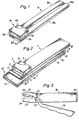
- a temperature measuring device is shown which is usable in association with the invention.
- a preferred temperature measuring device is shown, and this will therefore be described first.
- a sensor 1 which in the example shown is constituted by a thermistor.
- This thermistor consists of an inner ceramic material 2, whose electric resistance varies with the temperature.
- On its underside the thermistor is provided with two contacts 3 and 4, which for example may consist of a thin layer of silver.
- the thermistor is provided on its upper side with a silver contact 5 intended for trimming. The trimming may take place in such a manner that a small area 6 is removed from the contact by mechanical treatment, e.g. shot peening or with the help of a laster beam.
- the thermistor is arranged on a support 7 which consists of an inner plastic material 8 with outer metal coatings 9 and 10. These metal coatings may, for example, consist of copper.
- the support 7 is shortcircuited by a soldering 11 in such a manner that the metal coating 9 is in contact with a part 10' of the upper layer 10. This part 10' of the upper metal coating 10 is separated from the rest of this metal coating by a cut 12 which is intended to isolate electrically the two contacts 3 and 4 from one another.
- the support 7 with the thermistor 1 described above in turn is placed on a somewhat broader strip 13.
- This strip 13 may consist of an inner cardboard material with outer plastic coatings 15 and 16.
- the support 7 is placed so that the thermistor 1 is fully located within the surface 17 of the somewhat broader strip 13 carrying the support 7.
- the opposite end of the support on the other hand is arranged so that it projects beyond the somewhat broader strip 13.
- the idea behind this is that the part of the total construction shown to the right in fig. 2 should be capable of being dipped in an insulating plastic coating, so that the thermistor 1, the connecting contacts 3, 4 and 5 together with at least the nearest parts of the electric conductors 9 and 10 are enwrapped in a tight manner together with the corresponding end of the somewhat broader strip 13.
- This plastic coating may be made relatively thin with the help of transparent material and is therefore not shown in fig. 2.
- the sterile package, into which the construction is finally to be packed until its use, is also not shown.
- the measuring device in accordance with fig. 1 corresponds in principle to that according to fig. 2. Consequently, the same reference numerals have been used, but with the addition of the letter a. The main difference is that the two electric conductors 9a and 10a are arranged on one and the same side of the same supporting plastic layer 8a. Furthermore, this construction lacks the plastic-coated supporting sheet 13 of cardboard which is present in the construction according to fig. 2.
- a first embodiment of the device in accordance with the invention is described.
- This first embodiment is mainly adapted to the temperature measuring device shown in fig. 1 which has its contacts 9a and 10a arranged on one and the same side of a support 8a.
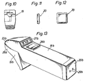
- the construction shown consists of a first tong-half 18 which is illustrated in fig. 4-7 and a second tong-half 19 which is illustrated in fig. 8-10. Furthermore, a lid 20 is included which is shown in fig. 11-12.
- the two tong-halves are mounted on each other with the help of an axle 21 and are normally retained in open position with the help of a spring 22.
- the tongs are thus closed against the effect of this spring.
- the tong-half 18 is provided at its front end, that is to say, the lower jaw 23, with a substantially V-shaped groove 24.
- the other tong-half 19 is provided at its front end, that is to say, the upper jaw 25, with a corresponding projection 26.
- This V-shaped groove and this projection respectively are shown in the figures with constant cross-section.
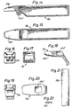
- Fig. 13 shows an embodiment of the subject of the invention which is preferred from a point of view of design. How this embodiment which is preferred from a point of view of design can be produced in practice should be evident from fig. 14-22, which show a similar technical construction, but of a somewhat modified shape.
- the construction according to fig. 13 thus consists of a square casing 18b which at its one end is closed by a lid 20b. At the front end of the casing 18b is mounted a finger-grip part 19b.
- the casing 18b moreover has a reading window 27b which forms part of a display unit present inside the device. Furthermore, the casing comprises an electric switch 28b which is operated when it is desired to read the temperature. At 29b finally an electrical connection is indicated for the possible recharging of a battery arranged inside the device.
- the construction according to fig. 14-22 also consists of a substantially square casing 18c and a grip part 19c. Moreover, a lid 20c is present.
- the finger grip part 19c is mounted in the casing 18c with the help of an axle (not shown) which is intended to be introduced into the holes 21c' and 21 c" respectively.
- the construction is to be provided with a spring (not shown) corresponding to the spring 22 in the construction according to fig. 3.
- This spring is appropriately arranged in such a manner, however, that it normally holds the two jaws 23c and 25c closed against one another. The opening of the tongs thus has to take place against the effect of the spring force.
- this spring force which will produce a certain defined pressure on the contact surfaces of the measuring device used.
- the line 30b indicates the outer contour for either the upper jaw 23b or for the lower jaw 25b.
- Numeral 31 b indicates the contour of the contact surface of the lower jaw, whilst 32b designates the corresponding contact surface of the upper jaw.
- the respective contact surfaces may consist of strips 33b and 34b respectively arranged in grooves 35b and 36b respectively in the upper jaw 23b and in the lower jaw 25b respectively.
- the strips should be made of a non-oxidizing material which gives good electric contact with e.g. copper.
- a non-oxidizing material which gives good electric contact with e.g. copper.
- an outer layer of silver or gold may be used.
- fig. 25 is shown how two electric conductors 31' can be placed in two grooves 36' in a lower jaw substantially corresponding to the lower jaw 23 in the embodiment according to fig. 3-12.
- fig. 26 a further contact arrangement is shown which is suitable for the embodiment of the subject of the invention shown in fig. 3-12.
- the lower jaw is designated 23" and the upper one 25".
- the electric contacts in the lower half are designated 31" and those in the upper half 32". Thanks to the contact sheet 38" and 39" it is sufficient here to connect only the contacts 31" to the working circuit included in the construction.
- the measuring device according to fig. 1 can be introduced between the jaws 23" and 25" with its top side turned either upwards or downwards.
- the measuring device according to fig. 1 can be modified in the manner as indicated in fig. 27 and 28.
- the whole measuring device 7d is folded over at the end remote from the thermistor 1 d, so that electric conductors 9d and 10d corresponding to 9a and 10a are present once again on both sides of the measuring device.
- Fig. 29-32 different contact arrangements are shown schematically.
- Fig. 29 and 31 correspond closest to that according to fig. 26.
- the construction according to fig. 30 substantially corresponds to the contact arrangement according to fig. 23-24.
- Fig. 32 shows that it is also possible to have two contacts in the one jaw and a wider contact in the other jaw.
- fig. 33 and 34 is shown schematically how the internal electrical equipment may be arranged so that it is readily exchangeable on a board 40' and 40" respectively.
- the numerals 41', 41"; 42', 42" and 43', 43" indicate the parts included such as e.g. a microprocessor, a transistor and a resistor respectively.
- the board 40' is subsequently connected electrically to the contacts 31 a' and 32a' via a spring sliding contact 44'.
- the board 40" is connected to the contacts 32a" and 31 a" via a connection cable 44", which means that the electrical parts may be taken out of the casing without the contact with contacts 31 a" and 32a" being broken.
- Numeral 1f designates the thermistor which forms part of the measuring device.
- 31 f and 32f designate the contact surfaces on the measuring device as well as the corresponding contact surfaces in the respective tong jaws.
- Numeral 45 designates a tuning and supply component which transmits a low current through 1f to measure the resistance of the same which varies with the temperature. The value obtained is tuned in the form of a signal to a processor 46 which may be said to constitute a small micro-computer.
- This micro-computer contains e.g. a clock and an arithmetic element which can be programmed for different programmes, e.g. for measurement in °C or in °F. The correct programme is selected with the help of a control unit 47.
- Numeral 48 designates an actuating button which is operated when reading is required.
- the value finally obtained is shown on a display unit 49.
- the source of energy required e.g. a battery, may be included e.g. in part 45. Alternatively, it can be arranged separately and be connected in a suitable manner to the remaining parts of the system.
- the component parts 45-49 may be varied in their construction and function within wide limits. It would serve no purpose therefore to describe these parts in greater detail. Anybody versed in the art who wishes to pursue the invention only needs to specify his wishes to a supplier of such parts, so that the latter can then "tailor-make" the parts in accordance with the wishes specified.
- thermocouple can be used, whose electromotoric force varies with the temperature.
Landscapes
- Physics & Mathematics (AREA)
- General Physics & Mathematics (AREA)
- Measuring And Recording Apparatus For Diagnosis (AREA)
- Measuring Temperature Or Quantity Of Heat (AREA)
Applications Claiming Priority (1)
| Application Number | Priority Date | Filing Date | Title |
|---|---|---|---|
| PCT/SE1978/000013 WO1980000192A1 (en) | 1978-07-03 | 1978-07-03 | A device for the gripping of a temperature measuring device and for the reading of measuring values obtained with the device |
Publications (2)
| Publication Number | Publication Date |
|---|---|
| EP0016752A1 EP0016752A1 (en) | 1980-10-15 |
| EP0016752B1 true EP0016752B1 (en) | 1983-10-05 |
Family
ID=20333565
Family Applications (1)
| Application Number | Title | Priority Date | Filing Date |
|---|---|---|---|
| EP78900189A Expired EP0016752B1 (en) | 1978-07-03 | 1980-02-12 | A device for gripping and for reading values obtained by means of a temperature measuring device |
Country Status (16)
| Country | Link |
|---|---|
| EP (1) | EP0016752B1 (enExample) |
| JP (1) | JPS5554422A (enExample) |
| AU (1) | AU527090B2 (enExample) |
| BE (1) | BE876695A (enExample) |
| CA (1) | CA1134646A (enExample) |
| DD (1) | DD144688A5 (enExample) |
| DE (1) | DE2862326D1 (enExample) |
| DK (1) | DK156329C (enExample) |
| ES (1) | ES481756A1 (enExample) |
| FI (1) | FI69705C (enExample) |
| IE (1) | IE47978B1 (enExample) |
| IT (1) | IT1202937B (enExample) |
| NL (1) | NL7905173A (enExample) |
| NO (1) | NO151059C (enExample) |
| PL (1) | PL121109B1 (enExample) |
| WO (1) | WO1980000192A1 (enExample) |
Families Citing this family (3)
| Publication number | Priority date | Publication date | Assignee | Title |
|---|---|---|---|---|
| JPS6150018A (ja) * | 1984-08-18 | 1986-03-12 | Omron Tateisi Electronics Co | カセツト型温度センサ |
| GB2168486B (en) * | 1984-11-08 | 1988-07-20 | Omron Tateisi Electronics Co | Electronic thermometer |
| JP6182750B2 (ja) * | 2013-04-04 | 2017-08-23 | 株式会社タニタ | 測定装置 |
Family Cites Families (9)
| Publication number | Priority date | Publication date | Assignee | Title |
|---|---|---|---|---|
| US3260114A (en) * | 1962-02-19 | 1966-07-12 | Jr Walter B Drolet | Temperature indicating device |
| US3642008A (en) * | 1968-09-25 | 1972-02-15 | Medical Plastics Inc | Ground electrode and test circuit |
| US3681993A (en) * | 1970-04-30 | 1972-08-08 | Sensitron Inc | Disposable clinical thermometer |
| LU63764A1 (enExample) * | 1971-08-24 | 1972-12-05 | ||
| US3949609A (en) * | 1972-01-31 | 1976-04-13 | Hammerslag Julius G | Resistance thermometer and disposable probe |
| US3999537A (en) * | 1973-10-25 | 1976-12-28 | United States Surgical Corporation | Temperature, pulse and respiration detector |
| US4095467A (en) * | 1975-07-09 | 1978-06-20 | Ipco Hospital Supply Corporation | Disposable tape cord thermometer |
| NO148233C (no) * | 1977-03-18 | 1983-09-07 | Milton Schonberger | Termometer til maaling av kroppstemperatur |
| US4200970A (en) * | 1977-04-14 | 1980-05-06 | Milton Schonberger | Method of adjusting resistance of a thermistor |
-
1978
- 1978-07-03 WO PCT/SE1978/000013 patent/WO1980000192A1/en not_active Ceased
- 1978-07-03 DE DE7878900189T patent/DE2862326D1/de not_active Expired
-
1979
- 1979-05-31 BE BE0/195511A patent/BE876695A/xx not_active IP Right Cessation
- 1979-06-11 IT IT7923456A patent/IT1202937B/it active
- 1979-06-21 ES ES481756A patent/ES481756A1/es not_active Expired
- 1979-06-27 FI FI792033A patent/FI69705C/fi not_active IP Right Cessation
- 1979-06-27 NO NO79792155A patent/NO151059C/no unknown
- 1979-06-29 DD DD79213995A patent/DD144688A5/de unknown
- 1979-06-29 CA CA000330842A patent/CA1134646A/en not_active Expired
- 1979-06-29 AU AU48522/79A patent/AU527090B2/en not_active Expired
- 1979-07-02 DK DK279479A patent/DK156329C/da not_active IP Right Cessation
- 1979-07-02 PL PL1979216794A patent/PL121109B1/pl unknown
- 1979-07-03 NL NL7905173A patent/NL7905173A/nl not_active Application Discontinuation
- 1979-07-03 JP JP8434879A patent/JPS5554422A/ja active Granted
- 1979-08-08 IE IE965/79A patent/IE47978B1/en not_active IP Right Cessation
-
1980
- 1980-02-12 EP EP78900189A patent/EP0016752B1/en not_active Expired
Also Published As
| Publication number | Publication date |
|---|---|
| WO1980000192A1 (en) | 1980-02-07 |
| DE2862326D1 (en) | 1983-11-10 |
| DK156329C (da) | 1989-12-27 |
| NL7905173A (nl) | 1980-01-07 |
| FI792033A7 (fi) | 1980-01-04 |
| IT7923456A0 (it) | 1979-06-11 |
| IE790965L (en) | 1980-01-03 |
| JPS6136608B2 (enExample) | 1986-08-19 |
| ES481756A1 (es) | 1980-02-16 |
| CA1134646A (en) | 1982-11-02 |
| AU4852279A (en) | 1980-01-10 |
| PL121109B1 (en) | 1982-04-30 |
| PL216794A1 (enExample) | 1980-04-08 |
| NO151059C (no) | 1985-01-30 |
| NO792155L (no) | 1980-01-04 |
| DK156329B (da) | 1989-08-07 |
| BE876695A (fr) | 1979-09-17 |
| DD144688A5 (de) | 1980-10-29 |
| JPS5554422A (en) | 1980-04-21 |
| IE47978B1 (en) | 1984-08-08 |
| NO151059B (no) | 1984-10-22 |
| FI69705B (fi) | 1985-11-29 |
| FI69705C (fi) | 1986-03-10 |
| AU527090B2 (en) | 1983-02-17 |
| DK279479A (da) | 1980-01-04 |
| IT1202937B (it) | 1989-02-15 |
| EP0016752A1 (en) | 1980-10-15 |
Similar Documents
| Publication | Publication Date | Title |
|---|---|---|
| EP0410186B1 (en) | Electronic clinical thermometer | |
| US6280397B1 (en) | High speed accurate temperature measuring device | |
| US4253334A (en) | Device for gripping and for reading of temperature values obtained by means of a temperature measuring device | |
| US4602642A (en) | Method and apparatus for measuring internal body temperature utilizing infrared emissions | |
| EP1783469B1 (en) | Electronic thermometer with flex circuit location | |
| US7036984B2 (en) | Digital thermometer for measuring body temperature | |
| US3367186A (en) | Resistance thermometer | |
| JPH04504367A (ja) | 耳温度検出装置 | |
| JPS5991925A (ja) | 鍋と蓋からなる炊事用容器、とくに蒸気圧力鍋 | |
| EP0022253B1 (en) | Individual gauge for the microclimate index | |
| US3593704A (en) | Pulse sensor for body pulse rate measuring means | |
| IE47978B1 (en) | A device for gripping and for reading values obtained by means of a temperature measuring device | |
| GB2168486A (en) | Electronic thermometer with disposal probe | |
| JP2006258790A (ja) | おしゃぶり体温計 | |
| SE421351B (sv) | Anordning for gripning av en temperaturmetaranordning och avlesning av medelst denna anordning erhalla metverden | |
| FR2448714A1 (fr) | Sonde de mesure de temperature avec capuchon jetable, capuchon a utiliser dans ce but et dispositif de mesure de temperature ainsi forme | |
| JPS6150023A (ja) | 電子温度計 | |
| JPH02265527A (ja) | 美容カウンセリング用皮膚温度測定方法およびそれに用いる装置 | |
| RU2090848C1 (ru) | Медицинский термометр | |
| US20060227848A1 (en) | Acupuncture needle thermocouple clip | |
| TWI276786B (en) | Digital thermometer for measuring body temperature | |
| JPS61120028A (ja) | 電子温度計 | |
| JPS61120030A (ja) | 電子温度計 | |
| JPH11178807A (ja) | 健康管理装置 | |
| JPH0862042A (ja) | 鼓膜温度計 |
Legal Events
| Date | Code | Title | Description |
|---|---|---|---|
| PUAI | Public reference made under article 153(3) epc to a published international application that has entered the european phase |
Free format text: ORIGINAL CODE: 0009012 |
|
| 17P | Request for examination filed | ||
| AK | Designated contracting states |
Designated state(s): CH DE FR GB LU SE |
|
| RAP1 | Party data changed (applicant data changed or rights of an application transferred) |
Owner name: CRAFON MEDICAL AB |
|
| GRAA | (expected) grant |
Free format text: ORIGINAL CODE: 0009210 |
|
| AK | Designated contracting states |
Kind code of ref document: B1 Designated state(s): CH DE FR GB LU SE |
|
| PG25 | Lapsed in a contracting state [announced via postgrant information from national office to epo] |
Ref country code: SE Effective date: 19831005 |
|
| ET | Fr: translation filed | ||
| REF | Corresponds to: |
Ref document number: 2862326 Country of ref document: DE Date of ref document: 19831110 |
|
| RAP2 | Party data changed (patent owner data changed or rights of a patent transferred) |
Owner name: GAMBRO CRAFON AKTIEBOLAG |
|
| REG | Reference to a national code |
Ref country code: CH Ref legal event code: PFA Free format text: GAMBRO CRAFON AKTIEBOLAG |
|
| REG | Reference to a national code |
Ref country code: FR Ref legal event code: CD |
|
| PLBE | No opposition filed within time limit |
Free format text: ORIGINAL CODE: 0009261 |
|
| STAA | Information on the status of an ep patent application or granted ep patent |
Free format text: STATUS: NO OPPOSITION FILED WITHIN TIME LIMIT |
|
| 26N | No opposition filed | ||
| REG | Reference to a national code |
Ref country code: FR Ref legal event code: ST |
|
| REG | Reference to a national code |
Ref country code: FR Ref legal event code: RC |
|
| REG | Reference to a national code |
Ref country code: FR Ref legal event code: DA |
|
| REG | Reference to a national code |
Ref country code: CH Ref legal event code: PFA Free format text: CRAFON AKTIEBOLAG |
|
| REG | Reference to a national code |
Ref country code: FR Ref legal event code: CA |
|
| REG | Reference to a national code |
Ref country code: LU Ref legal event code: CNA Free format text: 3820 16 CRAFON AKTIEBOLAG, C/O AB ASTRA LEGAL DEPARTMENT3820 16 -151 85 SOEDERTAELJE (SUEDE) |
|
| EPTA | Lu: last paid annual fee | ||
| PGFP | Annual fee paid to national office [announced via postgrant information from national office to epo] |
Ref country code: GB Payment date: 19970624 Year of fee payment: 20 |
|
| PGFP | Annual fee paid to national office [announced via postgrant information from national office to epo] |
Ref country code: FR Payment date: 19970709 Year of fee payment: 20 |
|
| PGFP | Annual fee paid to national office [announced via postgrant information from national office to epo] |
Ref country code: DE Payment date: 19970714 Year of fee payment: 20 |
|
| PGFP | Annual fee paid to national office [announced via postgrant information from national office to epo] |
Ref country code: CH Payment date: 19970730 Year of fee payment: 20 |
|
| PGFP | Annual fee paid to national office [announced via postgrant information from national office to epo] |
Ref country code: LU Payment date: 19970814 Year of fee payment: 20 |
|
| PG25 | Lapsed in a contracting state [announced via postgrant information from national office to epo] |
Ref country code: GB Free format text: LAPSE BECAUSE OF EXPIRATION OF PROTECTION Effective date: 19980702 Ref country code: CH Free format text: LAPSE BECAUSE OF EXPIRATION OF PROTECTION Effective date: 19980702 |
|
| PG25 | Lapsed in a contracting state [announced via postgrant information from national office to epo] |
Ref country code: LU Free format text: LAPSE BECAUSE OF EXPIRATION OF PROTECTION Effective date: 19980703 |
|
| REG | Reference to a national code |
Ref country code: GB Ref legal event code: PE20 Effective date: 19980702 |
|
| REG | Reference to a national code |
Ref country code: CH Ref legal event code: PL |