EP0016682B1 - Garniture de frein à disque et procédé pour sa fabrication - Google Patents
Garniture de frein à disque et procédé pour sa fabrication Download PDFInfo
- Publication number
- EP0016682B1 EP0016682B1 EP19800400307 EP80400307A EP0016682B1 EP 0016682 B1 EP0016682 B1 EP 0016682B1 EP 19800400307 EP19800400307 EP 19800400307 EP 80400307 A EP80400307 A EP 80400307A EP 0016682 B1 EP0016682 B1 EP 0016682B1
- Authority
- EP
- European Patent Office
- Prior art keywords
- organic material
- elements
- brake lining
- brake
- lining
- Prior art date
- Legal status (The legal status is an assumption and is not a legal conclusion. Google has not performed a legal analysis and makes no representation as to the accuracy of the status listed.)
- Expired
Links
- 238000000034 method Methods 0.000 title claims description 5
- 238000004519 manufacturing process Methods 0.000 title claims description 3
- 239000011368 organic material Substances 0.000 claims description 24
- 230000007797 corrosion Effects 0.000 claims description 9
- 238000005260 corrosion Methods 0.000 claims description 9
- 238000007731 hot pressing Methods 0.000 claims description 2
- 239000002184 metal Substances 0.000 description 10
- 230000002787 reinforcement Effects 0.000 description 5
- 235000012431 wafers Nutrition 0.000 description 4
- 229910000831 Steel Inorganic materials 0.000 description 3
- 238000012856 packing Methods 0.000 description 3
- 239000010959 steel Substances 0.000 description 3
- 239000010410 layer Substances 0.000 description 2
- 239000008188 pellet Substances 0.000 description 2
- FAPWRFPIFSIZLT-UHFFFAOYSA-M Sodium chloride Chemical compound [Na+].[Cl-] FAPWRFPIFSIZLT-UHFFFAOYSA-M 0.000 description 1
- 239000002519 antifouling agent Substances 0.000 description 1
- 238000006073 displacement reaction Methods 0.000 description 1
- 238000009826 distribution Methods 0.000 description 1
- 238000010438 heat treatment Methods 0.000 description 1
- 238000012986 modification Methods 0.000 description 1
- 230000004048 modification Effects 0.000 description 1
- 239000003973 paint Substances 0.000 description 1
- 239000011241 protective layer Substances 0.000 description 1
- 230000035939 shock Effects 0.000 description 1
- 239000011780 sodium chloride Substances 0.000 description 1
Images
Classifications
-
- F—MECHANICAL ENGINEERING; LIGHTING; HEATING; WEAPONS; BLASTING
- F16—ENGINEERING ELEMENTS AND UNITS; GENERAL MEASURES FOR PRODUCING AND MAINTAINING EFFECTIVE FUNCTIONING OF MACHINES OR INSTALLATIONS; THERMAL INSULATION IN GENERAL
- F16D—COUPLINGS FOR TRANSMITTING ROTATION; CLUTCHES; BRAKES
- F16D65/00—Parts or details
- F16D65/02—Braking members; Mounting thereof
- F16D65/04—Bands, shoes or pads; Pivots or supporting members therefor
- F16D65/092—Bands, shoes or pads; Pivots or supporting members therefor for axially-engaging brakes, e.g. disc brakes
- F16D65/095—Pivots or supporting members therefor
-
- F—MECHANICAL ENGINEERING; LIGHTING; HEATING; WEAPONS; BLASTING
- F16—ENGINEERING ELEMENTS AND UNITS; GENERAL MEASURES FOR PRODUCING AND MAINTAINING EFFECTIVE FUNCTIONING OF MACHINES OR INSTALLATIONS; THERMAL INSULATION IN GENERAL
- F16D—COUPLINGS FOR TRANSMITTING ROTATION; CLUTCHES; BRAKES
- F16D65/00—Parts or details
- F16D65/0025—Rust- or corrosion-preventing means
-
- F—MECHANICAL ENGINEERING; LIGHTING; HEATING; WEAPONS; BLASTING
- F16—ENGINEERING ELEMENTS AND UNITS; GENERAL MEASURES FOR PRODUCING AND MAINTAINING EFFECTIVE FUNCTIONING OF MACHINES OR INSTALLATIONS; THERMAL INSULATION IN GENERAL
- F16D—COUPLINGS FOR TRANSMITTING ROTATION; CLUTCHES; BRAKES
- F16D65/00—Parts or details
- F16D65/02—Braking members; Mounting thereof
- F16D65/04—Bands, shoes or pads; Pivots or supporting members therefor
- F16D65/092—Bands, shoes or pads; Pivots or supporting members therefor for axially-engaging brakes, e.g. disc brakes
-
- F—MECHANICAL ENGINEERING; LIGHTING; HEATING; WEAPONS; BLASTING
- F16—ENGINEERING ELEMENTS AND UNITS; GENERAL MEASURES FOR PRODUCING AND MAINTAINING EFFECTIVE FUNCTIONING OF MACHINES OR INSTALLATIONS; THERMAL INSULATION IN GENERAL
- F16D—COUPLINGS FOR TRANSMITTING ROTATION; CLUTCHES; BRAKES
- F16D69/00—Friction linings; Attachment thereof; Selection of coacting friction substances or surfaces
- F16D69/02—Composition of linings ; Methods of manufacturing
-
- F—MECHANICAL ENGINEERING; LIGHTING; HEATING; WEAPONS; BLASTING
- F16—ENGINEERING ELEMENTS AND UNITS; GENERAL MEASURES FOR PRODUCING AND MAINTAINING EFFECTIVE FUNCTIONING OF MACHINES OR INSTALLATIONS; THERMAL INSULATION IN GENERAL
- F16D—COUPLINGS FOR TRANSMITTING ROTATION; CLUTCHES; BRAKES
- F16D69/00—Friction linings; Attachment thereof; Selection of coacting friction substances or surfaces
- F16D69/04—Attachment of linings
- F16D69/0408—Attachment of linings specially adapted for plane linings
-
- F—MECHANICAL ENGINEERING; LIGHTING; HEATING; WEAPONS; BLASTING
- F16—ENGINEERING ELEMENTS AND UNITS; GENERAL MEASURES FOR PRODUCING AND MAINTAINING EFFECTIVE FUNCTIONING OF MACHINES OR INSTALLATIONS; THERMAL INSULATION IN GENERAL
- F16D—COUPLINGS FOR TRANSMITTING ROTATION; CLUTCHES; BRAKES
- F16D69/00—Friction linings; Attachment thereof; Selection of coacting friction substances or surfaces
- F16D2069/005—Friction linings; Attachment thereof; Selection of coacting friction substances or surfaces having a layered structure
-
- F—MECHANICAL ENGINEERING; LIGHTING; HEATING; WEAPONS; BLASTING
- F16—ENGINEERING ELEMENTS AND UNITS; GENERAL MEASURES FOR PRODUCING AND MAINTAINING EFFECTIVE FUNCTIONING OF MACHINES OR INSTALLATIONS; THERMAL INSULATION IN GENERAL
- F16D—COUPLINGS FOR TRANSMITTING ROTATION; CLUTCHES; BRAKES
- F16D69/00—Friction linings; Attachment thereof; Selection of coacting friction substances or surfaces
- F16D69/04—Attachment of linings
- F16D2069/0425—Attachment methods or devices
- F16D2069/045—Bonding
-
- F—MECHANICAL ENGINEERING; LIGHTING; HEATING; WEAPONS; BLASTING
- F16—ENGINEERING ELEMENTS AND UNITS; GENERAL MEASURES FOR PRODUCING AND MAINTAINING EFFECTIVE FUNCTIONING OF MACHINES OR INSTALLATIONS; THERMAL INSULATION IN GENERAL
- F16D—COUPLINGS FOR TRANSMITTING ROTATION; CLUTCHES; BRAKES
- F16D69/00—Friction linings; Attachment thereof; Selection of coacting friction substances or surfaces
- F16D69/04—Attachment of linings
- F16D2069/0425—Attachment methods or devices
- F16D2069/0483—Lining or lining carrier material shaped in situ
-
- F—MECHANICAL ENGINEERING; LIGHTING; HEATING; WEAPONS; BLASTING
- F16—ENGINEERING ELEMENTS AND UNITS; GENERAL MEASURES FOR PRODUCING AND MAINTAINING EFFECTIVE FUNCTIONING OF MACHINES OR INSTALLATIONS; THERMAL INSULATION IN GENERAL
- F16D—COUPLINGS FOR TRANSMITTING ROTATION; CLUTCHES; BRAKES
- F16D69/00—Friction linings; Attachment thereof; Selection of coacting friction substances or surfaces
- F16D69/04—Attachment of linings
- F16D2069/0425—Attachment methods or devices
- F16D2069/0491—Tools, machines, processes
Definitions
- the subject of the present invention is a disc brake lining comprising a metal support with zones made of organic material for protection against corrosion.
- an organic material reinforcement replaces the commonly used steel reinforcement, which has the advantage of eliminating corrosion.
- the brake pads currently have a steel frame which is covered with a layer of paint.
- these metal reinforcements 22, 22a which carry friction linings 23, 23a (FIG. 1) between which the braking disc 24 is disposed, are mounted with reduced clearance a in housings 25, 25a in which pistons 27 are mounted. , 27a for controlling the wafers.
- the displacement during braking of the metal armatures 22, 22a relative to the brake calipers 26, 26a is very low.
- the life of the protective paint on the metal support is short, because the wafer is exposed to the weather (especially passage through puddles or saline atmosphere) and that it undergoes thermal shocks consecutive to the heating during braking.
- the corrosion phenomenon is such that it causes the complete connection of the wafer and the stirrup, preventing any sliding.
- the disc brake lining comprising a metallic member for supporting the friction lining having sliding zones protected against corrosion, is characterized in that this protection consists of elements made of organic material, fixed on the support member.
- This arrangement makes it possible to use a metal support member resistant well to the thrust forces of the control piston and to obtain sliding zones of the support plate which do not risk corrosion.
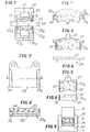
- FIG. 2 there is shown an embodiment of an improved disc brake lining according to the invention and which consists of a metal support member 28 to which a friction lining 29 is fixed.
- the ends 28a, 28b which slide, in the housings 25, 25a of the stirrups are provided with elements 30, 30a made of organic material having in section the shape of a U.
- the organic material elements 31, 31a integral with the ends of the metal support member 28 extend in two perpendicular planes.
- FIGS 5 and 6 there is shown an alternative embodiment of a brake lining in which the elements of organic material 32, 32a extend both on the lateral edges of the metallic support member 28 and of the friction lining 29.
- FIGS. 7 and 8 another alternative embodiment of a brake lining is shown in which the elements made of organic material extend at 33, 33a on the two lateral edges of the metal support member, which are in contact with the faces of the housings 25, 25a of the stirrups, a layer of organic material 34 being disposed between the friction lining and the metallic support member.
- the method used for producing a brake lining is similar to that of patent FR-A No. 2406128 in which a mold 6 having a bottom 7 and provided with a sliding piston 8 internally receives a friction lining preform 35 and an organic material preform 36 which are arranged above a metallic support member 37.
- the cold preforming of a pellet 36 of organic material intended to constitute the sliding zones is carried out with the stirrup.
Landscapes
- Engineering & Computer Science (AREA)
- General Engineering & Computer Science (AREA)
- Mechanical Engineering (AREA)
- Braking Arrangements (AREA)
Description
- La présente invention a pour objet une garniture de frein à disque comportant un support métallique avec des zones en matière organique de protection contre la corrosion.
- Dans le procédé suivant le brevet FR-A n° 2406128 pour la fabrication de garnitures de freins à disques comportant un organe de support sur lequel est fixée une garniture de friction, on dispose une préforme en matière organique du support et une préforme de garniture de friction dans un moule et on les soumet à une opération de pressage à chaud.
- Dans ce mode de réalisation une armature en matière organique remplace l'armature en acier communément utilisée, ce qui a pour avantage de supprimer la corrosion. En effet, les plaquettes de freins comportent actuellement une armature en acier qui est recouverte d'une couche de peinture. Or ces armatures métalliques 22, 22a qui portent des garnitures de friction 23, 23a (figure 1) entre lesquelles est disposé le disque de freinage 24, sont montées avec un jeu réduit a dans des logements 25, 25a dans lesquels sont montés des pistons 27, 27a de commande des plaquettes. Le déplacement pendant le freinage des armatures métalliques 22, 22a par rapport aux étriers de frein 26, 26a est très faible. Or la durée de vie de la peinture de protection du support métallique est faible, du fait que la plaquette se trouve exposée aux intempéries (notamment passage dans les flaques d'eau ou ambiance saline) et qu'elle subit des chocs thermiques consécutifs à l'échauffement pendant le freinage.
- Après la disparition de la couche protectrice, il se produit en général une corrosion du support métallique, corrosion qui favorise le collage du support métallique avec l'étrier de frein et qui perturbe le bon coulissement de la plaquette dans le logement de l'étrier. Dans certains cas, le phénomène de corrosion est tel qu'il provoque la solidarisation totale de la plaquette et de l'étrier, empêchant tout coulissement.
- Le fait d'utiliser une armature en matière organique qui elle est insensible à la corrosion, supprime tous les inconvénients mentionnés ci-dessus. Cependant il est difficile dans certains cas de remplacer purement et simplement le support métallique par un support en matière organique, la répartition des efforts n'étant pas la même dans tous les types de freins. En effet, l'armature organique présentant une résistance mécanique inférieure à l'acier, il est nécessaire que certaines zones de la plaquette, particulièrement les zones de poussée du piston, résistent aux efforts de poussée.
- Conformément à l'invention, la garniture de frein à disque, comportant un organe métallique de support de la garniture de friction ayant des zones de coulissement protégées contre la corrosion est caractérisée en ce que cette protection est constituée par des éléments en matière organique, fixés sur l'organe de support.
- Cette disposition permet d'utiliser un organe de support métallique résistant bien aux efforts de poussée du piston de commande et d'obtenir des zones de coulissement de la plaquette de support qui ne risquent pas la corrosion.
- D'autres caractéristiques et avantages de l'invention seront mieux compris à la lecture de la description qui va suivre de plusieurs modes de réalisation et en se référant aux dessins annexés, dans lesquels:
- - la figure 1 est une vue en plan d'un dispositif de freinage à disque de type connu;
- - la figure 2 est une vue en élévation d'un mode de réalisation d'une garniture de frein perfectionnée suivant l'invention;
- - la figure 3 est une vue en élévation d'un autre mode de réalisation d'une garniture de frein avec à chaque extrémité deux faces comportant un élément de glissement en matière organique;
- - la figure 4 est une vue en plan de la garniture représentée à la figure 3;
- - la figure 5 est une vue en élévation d'une garniture dans laquelle les bords de la garniture de freinage et la plaquette de support comportent des éléments latéraux en matière organique;
- - la figure 6 est une vue en plan de la garniture représentée à la figure 5;
- - la figure 7 est une vue en élévation et de la face arrière d'une garniture de frein dont la plaquette de support est munie de deux éléments latéraux en matière organique;
- - la figure 8 est une vue en plan de la garniture représentée à la figure 7;
- - la figure 9 est un moule dans lequel sont disposés les éléments constituant une garniture de frein.
- A la figure 2, on a représenté un mode de réalisation d'une garniture de frein à disque perfectionnée suivant l'invention et qui est constituée d'un organe de support métallique 28 sur lequel est fixée une garniture de friction 29.
- Conformément à l'invention, les extrémités 28a, 28b qui coulissent, dans les logements 25, 25a des étriers sont pourvues d'éléments 30, 30a en matière organique présentant en section la forme d'un U.
- Dans le mode de réalisation des figures 3 et 4, les éléments en matière organique 31, 31a solidaires des extrémités de l'organe de support métallique 28 s'étendent suivant deux plans perpendiculaires.
- Aux figures 5 et 6, on a représenté une variante de réalisation d'une garniture de freinage dans laquelle les éléments de matière organique 32, 32a s'étendent à la fois sur les bords latéraux de l'organe de support métallique 28 et de la garniture de friction 29.
- Aux figures 7 et 8, on a représenté une autre variante de réalisation d'une garniture de freinage dans laquelle les éléments en matière organique s'étendent en 33, 33a sur les deux bords latéraux de l'organe de support métallique, qui sont en contact avec les faces des logements 25, 25a des étriers, une' couche de matière organique 34 étant disposée entre la garniture de friction et l'organe de support métallique.
- Le procédé utilisé pour la réalisation d'une garniture de frein est analogue à celui du brevet FR-A n° 2406128 dans lequel un moule 6 présentant un fond 7 et muni d'un piston coulissant 8 reçoit intérieurement une préforme de garniture de friction 35 et une préforme de matière organique 36 qui sont disposées au-dessus d'un organe de support métallique 37.
- On réalise le préformage à froid d'une pastille 36 de matériau organique destinée à constituer les zones de coulissement avec l'étrier. On procède dans le moule 6 et avec le piston 8 à un surmoulage à chaud des pastilles 35 et 36 sur l'organe de support métallique 37.
- Bien entendu, diverses modifications peuvent être apportées par l'homme de l'art aux dispositifs ou procédés qui viennent d'être décrits uniquement à titre d'exemples non limitatifs, sans sortir du cadre de l'invention.
Claims (7)
Applications Claiming Priority (2)
| Application Number | Priority Date | Filing Date | Title |
|---|---|---|---|
| FR7906898A FR2452033A2 (fr) | 1979-03-19 | 1979-03-19 | Procede de fabrication de garnitures de freins a disques |
| FR7906898 | 1979-03-19 |
Publications (2)
| Publication Number | Publication Date |
|---|---|
| EP0016682A1 EP0016682A1 (fr) | 1980-10-01 |
| EP0016682B1 true EP0016682B1 (fr) | 1982-07-14 |
Family
ID=9223278
Family Applications (1)
| Application Number | Title | Priority Date | Filing Date |
|---|---|---|---|
| EP19800400307 Expired EP0016682B1 (fr) | 1979-03-19 | 1980-03-07 | Garniture de frein à disque et procédé pour sa fabrication |
Country Status (4)
| Country | Link |
|---|---|
| EP (1) | EP0016682B1 (fr) |
| JP (2) | JPS55126133A (fr) |
| DE (1) | DE3060662D1 (fr) |
| FR (1) | FR2452033A2 (fr) |
Families Citing this family (9)
| Publication number | Priority date | Publication date | Assignee | Title |
|---|---|---|---|---|
| DE3063532D1 (en) * | 1979-10-19 | 1983-09-01 | Lucas Ind Plc | Improvements in friction pad assemblies for vehicle disc brakes and in vehicle disc brakes |
| JPS5891935A (ja) * | 1981-11-26 | 1983-06-01 | Dainippon Ink & Chem Inc | ブレ−キ用成形物の製造法 |
| FI64443C (fi) * | 1982-01-26 | 1983-11-10 | Matti Tapanainen | Foerfarande foer framstaellning av en bromskloss |
| FI861501A0 (fi) * | 1986-04-09 | 1986-04-09 | Matti Tapanainen | Foerfarande foer framstaellning av bromskloss. |
| DE8614363U1 (fr) * | 1986-05-27 | 1987-10-01 | Textar Gmbh, 5090 Leverkusen, De | |
| DE3738949A1 (de) * | 1987-11-17 | 1989-05-24 | Textar Gmbh | Bremse fuer strassen-, schienen- und luftfahrzeuge |
| US5236528A (en) * | 1989-09-01 | 1993-08-17 | Sumitomo Electric Industries, Ltd. | Method for producing a friction member especially for a brake |
| DE102011051122A1 (de) * | 2011-06-17 | 2012-12-20 | Tmd Friction Services Gmbh | Reibbelagträgerplatte mit einer Korrosionsschutzschicht |
| DE102018202094B3 (de) * | 2018-02-12 | 2019-07-04 | Volkswagen Aktiengesellschaft | Scheibenbremsanordnung zur Reduzierung von Bremsscheibenkorrosion |
Family Cites Families (3)
| Publication number | Priority date | Publication date | Assignee | Title |
|---|---|---|---|---|
| US2791299A (en) * | 1954-10-08 | 1957-05-07 | Teofil L Bonkowski | Demountable brake lining |
| US3034625A (en) * | 1958-01-29 | 1962-05-15 | Demag Zug Gmbh | Axially displaceable coupling, brake and like friction means |
| FR1340988A (fr) * | 1962-09-15 | 1963-10-25 | Ferodo Sa | Patin de frottement pour frein à disque |
-
1979
- 1979-03-19 FR FR7906898A patent/FR2452033A2/fr active Granted
-
1980
- 1980-03-07 EP EP19800400307 patent/EP0016682B1/fr not_active Expired
- 1980-03-07 DE DE8080400307T patent/DE3060662D1/de not_active Expired
- 1980-03-19 JP JP3416980A patent/JPS55126133A/ja active Pending
-
1988
- 1988-12-06 JP JP30706488A patent/JPH0240888B2/ja not_active Expired - Lifetime
Also Published As
| Publication number | Publication date |
|---|---|
| JPS55126133A (en) | 1980-09-29 |
| EP0016682A1 (fr) | 1980-10-01 |
| DE3060662D1 (en) | 1982-09-02 |
| JPH023714A (ja) | 1990-01-09 |
| FR2452033A2 (fr) | 1980-10-17 |
| FR2452033B2 (fr) | 1983-08-26 |
| JPH0240888B2 (ja) | 1990-09-13 |
Similar Documents
| Publication | Publication Date | Title |
|---|---|---|
| EP0016682B1 (fr) | Garniture de frein à disque et procédé pour sa fabrication | |
| EP1608886B1 (fr) | Plaquettes de frein a disque ventilees | |
| FR2617923A1 (fr) | Palier spherique et son procede de fabrication | |
| CA2033417C (fr) | Plaquettes de freins a disque, concus tout particulierement pour des vehicules routiers et ferroviaires | |
| FR2487026A1 (fr) | Frein a disque a garnitures partielles et etrier flottant, notamment pour vehicules automobiles | |
| FR2489456A1 (fr) | Dispositif comportant une paire d'elements de friction, notamment frein ou embrayage a friction | |
| EP0988466B1 (fr) | Frein a disque a tube de guidage precontraint | |
| FR2486198A1 (fr) | Piece moulee destinee a etre sollicitee en flexion, notamment etrier de frein a disque | |
| FR2623263A1 (fr) | Frein pour vehicules routiers, ferroviaires et aeronefs | |
| FR2545897A1 (fr) | Frein a commande hydraulique muni d'un dispositif evitant une elevation de temperature excessive du liquide hydraulique | |
| FR2516189A1 (fr) | Dispositif hydraulique d'actionnement pour un frein | |
| FR2495253A1 (fr) | Frein a commande hydraulique muni d'un dispositif evitant l'echauffement du liquide hydraulique | |
| CA3002054C (fr) | Isolant haute friction | |
| FR2588342A1 (fr) | Agencement de disque de frein | |
| FR2564554A1 (fr) | Manchon d'etancheite pour broche de guidage de frein a disque | |
| FR2822208A1 (fr) | Procede d'obtention d'une garniture de friction d'embrayage, garniture de friction d'embrayage obtenue par un tel procede et disque d'embrayage equipe d'une telle garniture de friction | |
| FR2786837A1 (fr) | Recepteur hydraulique, notamment d'embrayage, a piston elastique | |
| FR2538485A1 (fr) | Dispositif de reajustement du reglage des garnitures d'un frein a friction, notamment d'un frein a tambour | |
| FR2495252A1 (fr) | Frein a commande hydraulique muni d'un dispositif evitant l'elevation de temperature du liquide hydraulique | |
| FR2640337A1 (fr) | Element en materiau de friction pour frein de vehicule | |
| BE890946A (fr) | Piston perfectionne pour freins a disque | |
| EP0038775A3 (fr) | Frein à disque pour véhicule | |
| FR2485135A1 (fr) | Bloc de friction pour freins a disques et procede de fabrication dudit bloc | |
| FR2611012A1 (fr) | Garniture de freinage a plots de materiau de friction rapportes | |
| FR2905743A1 (fr) | Patin de frein comportant un reservoir de graisse. |
Legal Events
| Date | Code | Title | Description |
|---|---|---|---|
| PUAI | Public reference made under article 153(3) epc to a published international application that has entered the european phase |
Free format text: ORIGINAL CODE: 0009012 |
|
| AK | Designated contracting states |
Designated state(s): DE GB IT |
|
| 17P | Request for examination filed |
Effective date: 19801015 |
|
| ITF | It: translation for a ep patent filed |
Owner name: JACOBACCI & PERANI S.P.A. |
|
| GRAA | (expected) grant |
Free format text: ORIGINAL CODE: 0009210 |
|
| AK | Designated contracting states |
Designated state(s): DE GB IT |
|
| REF | Corresponds to: |
Ref document number: 3060662 Country of ref document: DE Date of ref document: 19820902 |
|
| ITTA | It: last paid annual fee | ||
| PGFP | Annual fee paid to national office [announced via postgrant information from national office to epo] |
Ref country code: GB Payment date: 19970228 Year of fee payment: 18 |
|
| PGFP | Annual fee paid to national office [announced via postgrant information from national office to epo] |
Ref country code: DE Payment date: 19970319 Year of fee payment: 18 |
|
| PG25 | Lapsed in a contracting state [announced via postgrant information from national office to epo] |
Ref country code: GB Free format text: LAPSE BECAUSE OF NON-PAYMENT OF DUE FEES Effective date: 19980307 |
|
| GBPC | Gb: european patent ceased through non-payment of renewal fee |
Effective date: 19980307 |
|
| PG25 | Lapsed in a contracting state [announced via postgrant information from national office to epo] |
Ref country code: DE Free format text: LAPSE BECAUSE OF NON-PAYMENT OF DUE FEES Effective date: 19981201 |
|
| PLBE | No opposition filed within time limit |
Free format text: ORIGINAL CODE: 0009261 |
|
| STAA | Information on the status of an ep patent application or granted ep patent |
Free format text: STATUS: NO OPPOSITION FILED WITHIN TIME LIMIT |