EP0016653B1 - Method and apparatus for transverse stretching of a film or web - Google Patents
Method and apparatus for transverse stretching of a film or web Download PDFInfo
- Publication number
- EP0016653B1 EP0016653B1 EP80300902A EP80300902A EP0016653B1 EP 0016653 B1 EP0016653 B1 EP 0016653B1 EP 80300902 A EP80300902 A EP 80300902A EP 80300902 A EP80300902 A EP 80300902A EP 0016653 B1 EP0016653 B1 EP 0016653B1
- Authority
- EP
- European Patent Office
- Prior art keywords
- film
- web
- pulleys
- stretching
- selvedges
- Prior art date
- Legal status (The legal status is an assumption and is not a legal conclusion. Google has not performed a legal analysis and makes no representation as to the accuracy of the status listed.)
- Expired
Links
Images

Classifications
-
- D—TEXTILES; PAPER
- D06—TREATMENT OF TEXTILES OR THE LIKE; LAUNDERING; FLEXIBLE MATERIALS NOT OTHERWISE PROVIDED FOR
- D06C—FINISHING, DRESSING, TENTERING OR STRETCHING TEXTILE FABRICS
- D06C3/00—Stretching, tentering or spreading textile fabrics; Producing elasticity in textile fabrics
-
- B—PERFORMING OPERATIONS; TRANSPORTING
- B29—WORKING OF PLASTICS; WORKING OF SUBSTANCES IN A PLASTIC STATE IN GENERAL
- B29C—SHAPING OR JOINING OF PLASTICS; SHAPING OF MATERIAL IN A PLASTIC STATE, NOT OTHERWISE PROVIDED FOR; AFTER-TREATMENT OF THE SHAPED PRODUCTS, e.g. REPAIRING
- B29C55/00—Shaping by stretching, e.g. drawing through a die; Apparatus therefor
- B29C55/02—Shaping by stretching, e.g. drawing through a die; Apparatus therefor of plates or sheets
- B29C55/04—Shaping by stretching, e.g. drawing through a die; Apparatus therefor of plates or sheets uniaxial, e.g. oblique
- B29C55/08—Shaping by stretching, e.g. drawing through a die; Apparatus therefor of plates or sheets uniaxial, e.g. oblique transverse to the direction of feed
Definitions
- This invention relates to a method of effecting a transverse stretch or elongation of a fibrous web or film-like material and to an apparatus for carrying this method into practice.
- a typical example known in the art is a tentering system designed to grip the longitudinal edges or selvedges of an elongate sheet material and stretch this material transversely while it is heated.
- Such conventional devices are rather costly and space-consuming.
- magnification of stretch of a given material particularly where this material is non-fibrous such as a plastic film, is limited by the rupture which would take place at areas of the material where longitudinal stresses are created during progressive transverse stretching.
- British Patent No. 849436 describes a lateral stretching machine for synthetic polymer films in which a pair of pulleys are disposed at an acute angle to each other and engage the film at their area of closest proximity. The selvedges of the film are gripped by belts passing over the pulleys and as a result, the film is stretched laterally, for example to three times its original width.
- US Patent No. 2778057 also describes a lateral stretching machine of different construction.
- this machine the selvedges of the film are gripped at both sides between a pair of discs which rotate in the same plane as the film.
- the discs of each pair are angled so that the film is only gripped while passing around part of the disc circumference.
- the film may pass through a number of pairs of discs in sequence.
- the present invention seeks to provide a novel method of and apparatus for effecting a monoaxial (uniaxial), transverse stretching of a fibrous as well as film-like material of organic synthetic thermo-plastic polymer which will reduce or eliminate the foregoing drawbacks of the prior art.
- a method of transverse stretching of a longitudinally running continuous film, fibrous web or the like of organic synthetic thermoplastic polymeric material comprising gripping the film, web or the like (M) at its opposite selvedges, stretching the film, web or the like (M) transversely while heating it, and releasing the stretched film, web or the like (M) to allow it to cool and set, characterised in that the film, web or the like (M) is stretched by (a) gripping the selvedges respectively between (i) the periphery of each of a pair of symmetrically disposed pulleys of substantially the same dimensions rotating at substantially the same peripheral speed in the same plane but in opposite directions and (ii) each of a pair of endless belts trained around, and running with the respective pulley, the pulleys and the belts forming two divergent arcuate paths therebetween, and (b) moving the selvedge along the respective arcuate paths over a predetermined circumferential distance of from
- apparatus for transverse stretching of a longitudinally running continuous film, fibrous web or the like of an organic synthetic thermoplastic polymeric material comprising means for gripping the film, web or the like (M) between its selvedges and for stretching the film, web or the like (M) transversely, means (H) for heating the film, web or the like (M) during stretching, and means (29) for releasing the stretched film, web or the like (M) to allow it to cool and set, characterised in that the gripping and stretching means (11, 12, 17, 18) comprise a pair of pulleys (11, 12) of substantially the same dimensions disposed symmetrically in horizontal alignment and rotatable at substantially the same peripheral speed but in opposite directions, each pulley having a peripheral groove (27), and two endless belts (17, 18) each trained around the respective pulleys (11, 12) and of complementary cross section to the cross section of the grooves (27) and engaging therein, the pulleys (11, 12) and the belt
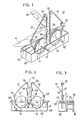
- FIG 1 there is shown a transverse stretching apparatus 10 embodying the invention.
- the apparatus 10 comprises a pair of pulleys 11, 12 of substantially the same dimensions disposed symmetrically in horizontal alignment across a reference centre line 13 ( Figure 2) and rotative in the same plane but in opposite directions as indicated by the arrows.
- the pulleys 11, 12 are shown to be rotatable in a substantially vertical common plane, although this plane of rotation may be varied anywhere between perpendicular to horizontal. Rotation in the vertical plane as shown is preferred for reasons of space-saving and ease of installation.
- the pulleys 11, 12 are supported on their respective shafts 11', 12' for rotation therewith, the shafts 11', 12' extending horizontally and supported in bearings 14, 15 on a rack 16, as shown in Figure 3.
- a pair of endless belts 17 and 18 of a "V" cross section are guided around their respective pulleys 11 and 12 and around respective first guide rollers 19, 20 and respective second guide rollers 21, 22 respectively.
- Either the pulleys 11, 12 or the belts 17, 18 or both may be driven by a drive source or associated actuating means (not shown), but in any event the pulleys 11, 12 must be rotated at substantially the same peripheral speed to effect uniform stretching of a material M.
- the material M to be stretched is in the form of an elongate sheet having a predetermined width.
- the sheet material M is fed to the apparatus 10 along the belts 17, 18 which are moving downwards substantially vertically to the apparatus 10 and is bent along both selvages thereof inwardly against the belts 17, 18 by a suitable selvage folding means such as is shown at 23.
- the folded selvages 24, 25 of the sheet M are then introduced between the pulleys 11, 12 and the belts 17, 18 respectively, and are each gripped by the V-section 26 of each belt engaging into a groove 27 formed in the periphery of each pulley, the groove 27 being complementary in shape to the V-section 26, as shown in Figure 4.
- the sheet M thus gripped is subjected to transverse stretching which progresses in an area defined by two divergently arcuate paths or lines of engagement between the respective pulleys and belts over a predetermined circumferential length of the pulleys 11, 12 measuring between the point of contact of the belts 17, 18 with the pulleys 11, 12 and the point of departure of the belts 17, 18 from the pulleys 11, 12.
- the length of these arcuate paths may be varied according to the extent to which the material M is stretched as desired and may normally range from a quarter to a half of the full pulley circumference.
- the magnification of stretch is thus determined by the range of the arcuate paths which may be chosen for an effective transverse length d of the material M, and it may be controlled expediently by adjusting the distance between the shafts 11' and 12' of the pulleys 11 and 12 of a given diameter as well as the angular position of the second guide rollers 21 and 22 relative to the axes of the pulleys 11 and 12, respectively.
- the sheet material M gripped between the belts 17, 18 and the pulleys 11, 12 is subjected to a relatively low tension during its movement in the area between the first quarters of the circumference of the pulleys where the stretching force is applied by the belts 17, 18.
- the magnification of stretch increases with an increase in the tension which in this region is applied by the pulleys, the selvedges 24, 25 of the material being held against the rigid peripheries of the pulleys. This ensures stable anchoring of the material M in place between the belts and the pulleys, eliminating the tendency of the gripped selvedges 24, 25 of the material M to slip out of engagement therebetween.
- the first guide rollers 19, 20 are positioned such that the opposite selvedges 24, 25 of the material M to be gripped on entry to the apparatus 10 may extend substantially in parallel relation.
- Designated at 28 is a vessel containing a liquid heating medium H to a level substantially flush with the axial line of the pulleys 11, 12, as shown in Figure 2.
- a roll member 29 disposed behind the pulleys 11, 12 opposite to the rack 16, the member 29 being adapted to withdraw the stretched portion of the material M after it has undergone substantially a semicircum- ferential stretching under heated conditions.
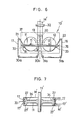
- FIG. 5-7 Illustrated in Figures 5-7 inclusive is a modified form of transverse stretching apparatus 10' according to the invention, wherein the same reference numerals and characters are used to refer to the same or like parts as appear in Figures 1-4.
- the endless V-belts 17, 18, as shown in Figures 5 and 6, are arranged to maintain engagement with a substantially semicircum- ferential area of the pulleys 11, 12 as in the case of the previously described embodiment.
- the belts 17, 18 are trained around the first guide rollers 19, 20 and the second guide rollers 21, 22 respectively, and further around additional sets of rollers 30a, and 30b and 31 a, 31b that are disposed in horizontal alignment below their respective associated pulleys 11, 12.
- the modified apparatus 10' functions basically in the same way as the first embodiment 10, but is particularly useful for handling a fibrous or film-like material M' of a tubular form, for which purpose there are provided additional endless V-belts 17', 18' for engagement with a corresponding additional groove 27' formed in the periphery of the pulleys 11, 12....
- Tubular material M' is fed between pinch rollers 31, 32 and advanced into the apparatus 10', where-upon the tubular web M' encases or envelops the first guide rollers 19, 20 and a portion of each of the endless belts 17, 17' and 18, 18', so that the tubular web M' is spread to permit portions of its periphery (corresponding to selvedges 24, 25) to be gripped in place from both inside and outside between the dual belts 17, 17', 18, 18' and the dually grooved pulleys 11, 12, as shown in Figures 5 and 6.
- the tubular material M' then undergoes monoaxial, transverse stretching in the manner already described.
- a cutter 33 is provided in the path of each of the belts 17, 18 adjacent to the position where the belts 17, 18, 17', 18' depart from the pulleys 11, 12 or the stretching of the material M' terminates.
- the cutters 33 are each received in a recess 34 formed in the periphery of each of the pulleys 11, 12 between the dual grooves 27, 27'.
- the cutters 33 are adapted to sever the selvedge portions of the tubular web M' upon completion of the intended stretching so that the tubular web M' is slit into two halves for withdrawal one over a roll member 35 at the front and the other over a roll member 36 at the back of the pulleys 11, 12 respectively, as shown in Figure 5. Thereafter the stretched material M' is released to allow it to cool and set.
- Designated at 37 is a casing surrounding the pulleys 11, 12 and accommodating a suitable heating medium such as live steam for heating the tubular material M'.
- the heating medium in the practice of the invention may be liquid and steam, as illustrated, or may be hot air or radiant heat, whichever is more convenient for a given material and for given stretching conditions.
- the magnification or extent to which the material M' is to be stretched may be adjusted by varying the distance between the two pulley shafts 11' and 12' and the angular position of the second guide rollers 21 and 22 with respect to the axes of the pulleys 11 and 12, respectively, as described in connection with the first apparatus 10 shown in Figures 1-4.
- the film will undergo satisfactory monoaxial transverse stretching if the condition of is met where 0 is the angle of rotation of pulleys 11, 12 initiating at the horizontal line connecting the centre axes of the two pulleys 11 and 12 and is the magnification of stretch; a unit length (which is assumed to be 1) of the unstretched starting film is reduced to a length equal to cos 0 when the stretching has been completed.
- the film receives, in addition to transverse stretching tension, another tension, exerted in the longitudinal direction.
- another tension exerted in the longitudinal direction.
- molecular orientation of the film will occur in the longitudinal direction too or the film can often become ruptured if the magnification of stretch is increased.
- the pulleys must have a diameter such that the stretching terminates at a pulley position defined by where the belts are released from the pulleys.
- the stretched film should be withdraw at such a speed and in such a manner as to hold the stretched film under minimum tension by, for example, providing a suitable warp material where the selvedge portions of the film, which remain unchanged in length, sag.
- transverse stretching can take place at an increased angle of rotation 0, effectively utilizing the semicircumference of the pulley, if an excess rate of unstretched film is fed in the form of a film with fine transverse creases or is fed by means of pulleys and belts having mutually engaging teeth or corrugated surfaces for gripping of the film.
Landscapes
- Engineering & Computer Science (AREA)
- Mechanical Engineering (AREA)
- Textile Engineering (AREA)
- Shaping By String And By Release Of Stress In Plastics And The Like (AREA)
Applications Claiming Priority (2)
| Application Number | Priority Date | Filing Date | Title |
|---|---|---|---|
| JP34027/79 | 1979-03-22 | ||
| JP3402779A JPS55126427A (en) | 1979-03-22 | 1979-03-22 | Lateral stretching device for film and fibrous material |
Publications (2)
| Publication Number | Publication Date |
|---|---|
| EP0016653A1 EP0016653A1 (en) | 1980-10-01 |
| EP0016653B1 true EP0016653B1 (en) | 1984-09-05 |
Family
ID=12402877
Family Applications (1)
| Application Number | Title | Priority Date | Filing Date |
|---|---|---|---|
| EP80300902A Expired EP0016653B1 (en) | 1979-03-22 | 1980-03-21 | Method and apparatus for transverse stretching of a film or web |
Country Status (6)
| Country | Link |
|---|---|
| US (1) | US4349500A (enExample) |
| EP (1) | EP0016653B1 (enExample) |
| JP (1) | JPS55126427A (enExample) |
| AU (1) | AU532336B2 (enExample) |
| CA (1) | CA1145522A (enExample) |
| DE (1) | DE3069093D1 (enExample) |
Families Citing this family (45)
| Publication number | Priority date | Publication date | Assignee | Title |
|---|---|---|---|---|
| JPS5658831A (en) * | 1979-10-19 | 1981-05-22 | Polymer Processing Res Inst | Biaxial stretching apparatus of tubular film |
| JPS578117A (en) * | 1980-06-17 | 1982-01-16 | Kobe Steel Ltd | Film orienting apparatus |
| JPS5741923A (en) * | 1980-08-26 | 1982-03-09 | Kobe Steel Ltd | Biaxially stretching apparatus of film |
| JPS6334904Y2 (enExample) * | 1980-11-21 | 1988-09-16 | ||
| JPS57163532A (en) | 1981-04-01 | 1982-10-07 | Polymer Processing Res Inst | Method for orienting film to traverse direction mainly |
| EP0090874A1 (de) * | 1982-04-07 | 1983-10-12 | Kurt Ehemann Spezialmaschinenfabrik GmbH & Co. KG | Textilwarenzuführvorrichtung für Ausrüstmaschinen |
| JPS58219024A (ja) * | 1982-06-15 | 1983-12-20 | Polymer Processing Res Inst | 膜・繊維材の延伸方法並びに装置 |
| US4711751A (en) * | 1985-01-11 | 1987-12-08 | Thermo Plastic Research Co., Ltd. | Process and apparatus for stretching tubular extruded plastic material |
| US5002782A (en) * | 1985-10-08 | 1991-03-26 | W. R. Grace & Co.-Conn. | Perforated cook-in shrink bag |
| US5086924A (en) * | 1985-10-08 | 1992-02-11 | W. R. Grace & Co. - Conn. | Perforated cook-in shrink bag |
| KR0162706B1 (ko) | 1994-06-20 | 1998-12-01 | 사이카와 겐조오 | 규제된 신축성 복합체 |
| WO1997024216A1 (en) * | 1994-07-01 | 1997-07-10 | Nippon Petrochemicals Company, Limited | Device for transversely extending a belt-like body |
| JP3431706B2 (ja) * | 1994-12-16 | 2003-07-28 | 新日本石油化学株式会社 | 積層体・不織布または織布並びにそれらを用いた強化積層体 |
| US6054086A (en) * | 1995-03-24 | 2000-04-25 | Nippon Petrochemicals Co., Ltd. | Process of making high-strength yarns |
| US6916440B2 (en) * | 2001-05-31 | 2005-07-12 | 3M Innovative Properties Company | Processes and apparatus for making transversely drawn films with substantially uniaxial character |
| US7153122B2 (en) * | 2002-05-28 | 2006-12-26 | 3M Innovative Properties Company | Apparatus for making transversely drawn films with substantially uniaxial character |
| US6949212B2 (en) * | 2002-11-27 | 2005-09-27 | 3M Innovative Properties Company | Methods and devices for stretching polymer films |
| US6936209B2 (en) * | 2002-11-27 | 2005-08-30 | 3M Innovative Properties Company | Methods and devices for processing polymer films |
| US7198742B2 (en) * | 2003-12-30 | 2007-04-03 | Kimberly-Clark Worldwide, Inc. | Apparatus and method for deforming sheet material |
| US20060138705A1 (en) * | 2004-12-23 | 2006-06-29 | Korba Gary A | Method of making a structured surface article |
| US20060138702A1 (en) * | 2004-12-23 | 2006-06-29 | Biernath Rolf W | Method of making uniaxially oriented articles having structured surfaces |
| US20060141218A1 (en) * | 2004-12-23 | 2006-06-29 | Biernath Rolf W | Uniaxially oriented articles having structured surface |
| US20060138686A1 (en) * | 2004-12-23 | 2006-06-29 | Ouderkirk Andrew J | Method of making a uniaxially stretched polymeric film having structured surface |
| US20060141220A1 (en) * | 2004-12-23 | 2006-06-29 | Merrill William W | Uniaxially oriented article having a structured surface |
| US20060141219A1 (en) * | 2004-12-23 | 2006-06-29 | Benson Olester Jr | Roll of a uniaxially oriented article having a structured surface |
| US20060138694A1 (en) * | 2004-12-23 | 2006-06-29 | Biernath Rolf W | Method of making a polymeric film having structured surfaces via replication |
| US20060204720A1 (en) * | 2004-12-23 | 2006-09-14 | Biernath Rolf W | Uniaxially oriented birefringent article having a structured surface |
| US20060226561A1 (en) | 2005-04-08 | 2006-10-12 | 3M Innovative Properties Company | Heat setting optical films |
| US7850810B2 (en) * | 2005-07-29 | 2010-12-14 | Gore Enterprise Holdings, Inc. | Method of making porous self-cohered web materials |
| US7655584B2 (en) * | 2005-07-29 | 2010-02-02 | Gore Enterprise Holdings, Inc. | Highly porous self-cohered web materials |
| US8048503B2 (en) * | 2005-07-29 | 2011-11-01 | Gore Enterprise Holdings, Inc. | Highly porous self-cohered web materials |
| US7604668B2 (en) * | 2005-07-29 | 2009-10-20 | Gore Enterprise Holdings, Inc. | Composite self-cohered web materials |
| US7655288B2 (en) * | 2005-07-29 | 2010-02-02 | Gore Enterprise Holdings, Inc. | Composite self-cohered web materials |
| US20070026040A1 (en) * | 2005-07-29 | 2007-02-01 | Crawley Jerald M | Composite self-cohered web materials |
| US20070026039A1 (en) * | 2005-07-29 | 2007-02-01 | Drumheller Paul D | Composite self-cohered web materials |
| US20070027551A1 (en) * | 2005-07-29 | 2007-02-01 | Farnsworth Ted R | Composite self-cohered web materials |
| US7418202B2 (en) * | 2005-08-04 | 2008-08-26 | 3M Innovative Properties Company | Article having a birefringent surface and microstructured features having a variable pitch or angles for use as a blur filter |
| US9134471B2 (en) * | 2006-06-28 | 2015-09-15 | 3M Innovative Properties Company | Oriented polymeric articles and method |
| JP5540898B2 (ja) * | 2010-06-01 | 2014-07-02 | トヨタ自動車株式会社 | 延伸装置 |
| JP6167987B2 (ja) * | 2014-05-14 | 2017-07-26 | トヨタ自動車株式会社 | 膜材搬送方法および膜材延伸装置 |
| JP6138094B2 (ja) | 2014-09-19 | 2017-05-31 | Jxtgエネルギー株式会社 | 網状不織布 |
| JP6499927B2 (ja) | 2015-06-10 | 2019-04-10 | Jxtgエネルギー株式会社 | 網状構造体 |
| CN106493931B (zh) * | 2016-12-22 | 2018-09-07 | 太仓市律点信息技术有限公司 | 一种麻醉机用硅胶管生产线的引管装置 |
| WO2018184911A1 (en) | 2017-04-03 | 2018-10-11 | Tata Steel Ijmuiden B.V. | Process for producing a polymer coated metal substrate and a metal strip substrate provided with a polymer coating |
| CN115139504B (zh) * | 2022-08-31 | 2022-11-25 | 山东永健机械有限公司 | 一种薄膜拉伸设备 |
Family Cites Families (8)
| Publication number | Priority date | Publication date | Assignee | Title |
|---|---|---|---|---|
| US2778057A (en) * | 1953-04-02 | 1957-01-22 | Stanley M Clark | Method and apparatus for continuously stretching plastic film |
| GB849436A (en) * | 1957-09-11 | 1960-09-28 | Ici Ltd | Synthetic polymer films |
| FR1213605A (fr) * | 1957-09-11 | 1960-04-01 | Ici Ltd | Pellicules en polymères synthétiques |
| US2988772A (en) * | 1958-05-26 | 1961-06-20 | Celanese Corp | Film stretching |
| AT211538B (de) * | 1958-08-25 | 1960-10-25 | Ici Ltd | Verfahren zum Querstrecken von flachen Filmen aus isotaktischem Polypropylen |
| US3254148A (en) * | 1963-01-10 | 1966-05-31 | Goodyear Tire & Rubber | Film stretching process |
| US3581344A (en) * | 1967-08-21 | 1971-06-01 | Dow Chemical Co | Apparatus for the preparation of biaxially oriented film |
| ES391123A1 (es) * | 1970-05-19 | 1974-05-01 | Hoechst Ag | Procedimiento y aparato para el estiramiento de laminas de material sintetico termoplastico. |
-
1979
- 1979-03-22 JP JP3402779A patent/JPS55126427A/ja active Granted
-
1980
- 1980-03-21 CA CA000348137A patent/CA1145522A/en not_active Expired
- 1980-03-21 EP EP80300902A patent/EP0016653B1/en not_active Expired
- 1980-03-21 AU AU56715/80A patent/AU532336B2/en not_active Expired
- 1980-03-21 DE DE8080300902T patent/DE3069093D1/de not_active Expired
- 1980-03-24 US US06/133,146 patent/US4349500A/en not_active Expired - Lifetime
Also Published As
| Publication number | Publication date |
|---|---|
| JPS55126427A (en) | 1980-09-30 |
| JPS5730368B2 (enExample) | 1982-06-28 |
| CA1145522A (en) | 1983-05-03 |
| AU532336B2 (en) | 1983-09-29 |
| EP0016653A1 (en) | 1980-10-01 |
| DE3069093D1 (en) | 1984-10-11 |
| US4349500A (en) | 1982-09-14 |
| AU5671580A (en) | 1980-09-25 |
Similar Documents
| Publication | Publication Date | Title |
|---|---|---|
| EP0016653B1 (en) | Method and apparatus for transverse stretching of a film or web | |
| US4525317A (en) | Method and apparatus for stretching film or fibrous web | |
| CA1074074A (en) | Stretching webs of sheet material | |
| EP0061931B1 (en) | Method and apparatus for stretching thermoplastic polymer films | |
| EP2346668B1 (en) | Film stretcher | |
| US5043036A (en) | Width stretching device | |
| EP2212098B1 (en) | Method and apparatus for longitudinal orientation of thermoplastic film material | |
| US4336638A (en) | Apparatus for stretching plastic webs | |
| US3682760A (en) | Oriented webs and method for making the same | |
| EP0027735B1 (en) | Method and apparatus for manufacturing stretched sheets from a tubular film | |
| EP0004092A2 (en) | A method and means for continuously thermal forming oriented thermoplastic molded articles | |
| US3445886A (en) | Apparatus for transversely stretching moving film | |
| US3193873A (en) | Device for the continuous simultaneous transverse and longitudinal drawing of thermoplastic strips | |
| GB1073741A (en) | Process and apparatus for producing multifilament material and products produced therefrom | |
| US5394595A (en) | Method and apparatus for shrinking biaxially stretched thermoplastic films | |
| JPH09118461A (ja) | ウェブの拡幅方法および装置 | |
| EP0087399B1 (en) | Apparatus for transversely stretching a foil of plastic material | |
| US3570051A (en) | Apparatus for biaxially stretching foil sheets or webs | |
| US3460194A (en) | Apparatus for dimensional stabilization of thermoplastic film | |
| JPS6343214B2 (enExample) | ||
| KR820001496B1 (ko) | 연속적으로 전진하는 유연성웨브를 횡방향으로 연신시키며 분자상으로 배향시키는 장치 | |
| US4414803A (en) | False twisting apparatus | |
| US3223766A (en) | Base film oscillation | |
| JP2686152B2 (ja) | 環状フィルムの延伸装置 | |
| JPH0416057B2 (enExample) |
Legal Events
| Date | Code | Title | Description |
|---|---|---|---|
| PUAI | Public reference made under article 153(3) epc to a published international application that has entered the european phase |
Free format text: ORIGINAL CODE: 0009012 |
|
| AK | Designated contracting states |
Designated state(s): DE FR GB IT NL |
|
| 17P | Request for examination filed |
Effective date: 19810323 |
|
| ITF | It: translation for a ep patent filed | ||
| GRAA | (expected) grant |
Free format text: ORIGINAL CODE: 0009210 |
|
| AK | Designated contracting states |
Designated state(s): DE FR GB IT NL |
|
| REF | Corresponds to: |
Ref document number: 3069093 Country of ref document: DE Date of ref document: 19841011 |
|
| ET | Fr: translation filed | ||
| PLBE | No opposition filed within time limit |
Free format text: ORIGINAL CODE: 0009261 |
|
| STAA | Information on the status of an ep patent application or granted ep patent |
Free format text: STATUS: NO OPPOSITION FILED WITHIN TIME LIMIT |
|
| 26N | No opposition filed | ||
| ITTA | It: last paid annual fee | ||
| PGFP | Annual fee paid to national office [announced via postgrant information from national office to epo] |
Ref country code: GB Payment date: 19990309 Year of fee payment: 20 |
|
| PGFP | Annual fee paid to national office [announced via postgrant information from national office to epo] |
Ref country code: FR Payment date: 19990329 Year of fee payment: 20 |
|
| PGFP | Annual fee paid to national office [announced via postgrant information from national office to epo] |
Ref country code: NL Payment date: 19990331 Year of fee payment: 20 |
|
| PGFP | Annual fee paid to national office [announced via postgrant information from national office to epo] |
Ref country code: DE Payment date: 19990528 Year of fee payment: 20 |
|
| PG25 | Lapsed in a contracting state [announced via postgrant information from national office to epo] |
Ref country code: GB Free format text: LAPSE BECAUSE OF EXPIRATION OF PROTECTION Effective date: 20000320 |
|
| PG25 | Lapsed in a contracting state [announced via postgrant information from national office to epo] |
Ref country code: NL Free format text: LAPSE BECAUSE OF EXPIRATION OF PROTECTION Effective date: 20000321 |
|
| REG | Reference to a national code |
Ref country code: GB Ref legal event code: PE20 Effective date: 20000320 |
|
| NLV7 | Nl: ceased due to reaching the maximum lifetime of a patent |
Effective date: 20000321 |