EP0015529B1 - Labelling apparatus - Google Patents
Labelling apparatus Download PDFInfo
- Publication number
- EP0015529B1 EP0015529B1 EP80101053A EP80101053A EP0015529B1 EP 0015529 B1 EP0015529 B1 EP 0015529B1 EP 80101053 A EP80101053 A EP 80101053A EP 80101053 A EP80101053 A EP 80101053A EP 0015529 B1 EP0015529 B1 EP 0015529B1
- Authority
- EP
- European Patent Office
- Prior art keywords
- ribbon
- roll
- clamping device
- label
- take
- Prior art date
- Legal status (The legal status is an assumption and is not a legal conclusion. Google has not performed a legal analysis and makes no representation as to the accuracy of the status listed.)
- Expired
Links
Images

Classifications
-
- B—PERFORMING OPERATIONS; TRANSPORTING
- B65—CONVEYING; PACKING; STORING; HANDLING THIN OR FILAMENTARY MATERIAL
- B65C—LABELLING OR TAGGING MACHINES, APPARATUS, OR PROCESSES
- B65C9/00—Details of labelling machines or apparatus
- B65C9/40—Controls; Safety devices
- B65C9/42—Label feed control
- B65C9/44—Label feed control by special means responsive to marks on labels or articles
-
- B—PERFORMING OPERATIONS; TRANSPORTING
- B65—CONVEYING; PACKING; STORING; HANDLING THIN OR FILAMENTARY MATERIAL
- B65C—LABELLING OR TAGGING MACHINES, APPARATUS, OR PROCESSES
- B65C9/00—Details of labelling machines or apparatus
- B65C9/08—Label feeding
- B65C9/18—Label feeding from strips, e.g. from rolls
- B65C9/1865—Label feeding from strips, e.g. from rolls the labels adhering on a backing strip
- B65C9/1876—Label feeding from strips, e.g. from rolls the labels adhering on a backing strip and being transferred by suction means
- B65C9/1884—Label feeding from strips, e.g. from rolls the labels adhering on a backing strip and being transferred by suction means the suction means being a movable vacuum arm or pad
-
- Y—GENERAL TAGGING OF NEW TECHNOLOGICAL DEVELOPMENTS; GENERAL TAGGING OF CROSS-SECTIONAL TECHNOLOGIES SPANNING OVER SEVERAL SECTIONS OF THE IPC; TECHNICAL SUBJECTS COVERED BY FORMER USPC CROSS-REFERENCE ART COLLECTIONS [XRACs] AND DIGESTS
- Y10—TECHNICAL SUBJECTS COVERED BY FORMER USPC
- Y10T—TECHNICAL SUBJECTS COVERED BY FORMER US CLASSIFICATION
- Y10T156/00—Adhesive bonding and miscellaneous chemical manufacture
- Y10T156/17—Surface bonding means and/or assemblymeans with work feeding or handling means
- Y10T156/1702—For plural parts or plural areas of single part
- Y10T156/1705—Lamina transferred to base from adhered flexible web or sheet type carrier
- Y10T156/1707—Discrete spaced laminae on adhered carrier
- Y10T156/171—Means serially presenting discrete base articles or separate portions of a single article
Landscapes
- Labeling Devices (AREA)
Abstract
Description
Die Erfindung betrifft eine Etikettiervorrichtung der im Oberbegriff des Patentanspruchs 1 angegebenen Gattung.The invention relates to a labeling device of the type specified in the preamble of claim 1.
Es ist eine Etikettiervorrichtung dieser Art bekannt (DE-A1-2 516 195), die vollpneumatisch arbeitet und die vor allem für den automatischen Betrieb in explosionsgefährdeten Räumen bestimmt ist. Der Bandvorzug erfolgt dort über gegeneinander und gegen das Etikettenband andrückende Vorzugrollen, die durch einen Pneumatikmotor antreibbar sind. Der Vorzugmechanismus wird über eine Luftschranke, die auf im Etikettenband angeordnete Steuerlöcher anspricht, gesteuert. In der Praxis hat es sich gezeigt, daß es beim automatischen Betrieb einer solchen Etikettiervorrichtung immer wieder zu Betriebsstörungen kommt, weil die Luftschranke z. B. wegen fehlender oder verstopfter Steuerlöcher im Etikettenband nicht anspricht. Dabei kann es zu Mehrfachetikettierungen oder Etikettenstaus kommen, die eine Abschaltung der Etikettiervorrichtung und der Förderanlage für die zu etikettierenden Gegenstände notwendig machen können. Hinzu kommt, daß sowohl für den Vorzugmechanismus als auch für eine eventuelle Bandaufwicklung unter ständiger Wechselbeanspruchung stehende Getriebemotore vorgesehen sind, die wegen einer kaum zu vermeidenden Verschleißanfälligkeit vor allem bei Dauerbetrieb eine häufige Wartung erfordern.A labeling device of this type is known (DE-A1-2 516 195), which operates fully pneumatically and which is primarily intended for automatic operation in potentially explosive areas. The tape is fed there by means of preferred rollers pressing against each other and against the label tape, which can be driven by a pneumatic motor. The preferred mechanism is controlled by an air barrier that responds to control holes located in the label tape. In practice, it has been shown that the automatic operation of such a labeling device always leads to malfunctions, because the air barrier z. B. does not respond due to missing or clogged control holes in the label tape. This can lead to multiple labeling or label jams, which can make it necessary to switch off the labeling device and the conveyor system for the objects to be labeled. In addition, both for the preferred mechanism as well as for a possible tape rewinder under constant alternating stress gear motors are provided, which require frequent maintenance because of a prone to wear, especially during continuous operation.
Bei einer anderen Etikettiervorrichtung für Etikettenbänder ohne Steuermarkierungen ist es an sich bekannt (US-A-3 953 278), als Vorzugmechanismus eine in Vorzugrichtung um den Etikettenabstand vor- und zurückbewegbare, bei der Vorwärtsbewegung das Etikettenband festhaltende und bei der Zurückbewegung offene Bandklemmeinrichtung zu verwenden. Die Steuerung des Vorzugmechanismus erfolgt dort ausschließlich über einen durch die vorbeibewegten zu etikettierenden Gegenstände betätigbaren Mikroschalter, während der Vorschubweg der Bandklemmeinrichtung über einen verstellbaren Anschlag auf das Etikettenmaß einstellbar ist. Da bei der Vorschubbewegung aber eine Orientierung am tatsächlichen Etikettenmaß fehlt, können vor allem bei Massenetikettierungen schon geringfügige Abweichungen der genannten Einstellung gegenüber dem Etikettenabstand, die im Hinblick auf die herstellungstechnischen Toleranzen, die Wärmeausdehnung und die Feuchtigkeitsausdehnung des Etikettenbandes nicht vermeidbar sind, unerwünschte Fehletikettierungen auftreten. Die durch ein Reibungsglied gebremste Abzugsrolle wird über das abziehende Etikettenband angetrieben, während die Aufwickelrolle für das leere Etikettenband mit Hilfe eines eigens hierfür vorgesehenen Motors antreibbar ist. In Vorzugsrichtung hinter der beweglichen Bandklemmeinrichtung ist eine im Gegentakt zu dieser betätigbare ortsfeste Bandklemmeinrichtung angeordnet, die beim Zurückbewegen der beweglichen Bandklemmeinrichtung einen Bandabzug von der Aufwickelrolle verhindern soll. Beim Betrieb mit Selbstklebeetiketten werden unvermeidlich Kleberspuren vom leeren Etikettenband auf die Klemmbacken der Bandklemmeinrichtungen übertragen, die sich dort allmählich ansammeln und zu Hafterscheinungen zwischen Klemmbacken und leeren Etikettenband führen. Während sich die bewegliche Bandklemmeinrichtung beim Zurückbewegen mit offenen Klemmbacken von einem anhaftenden leeren Etikettenband aus eigener Kraft lösen kann, ist dies bei der ortsfesten Bandklemmeinrichtung nicht der Fall, so daß es dort beim Vorschub infolge der Biegeschlaffheit des leeren Etikettenbandes leicht zu einem Bandstau und damit zu folgeschweren Betriebsstörungen kommen kann.In another labeling device for label tapes without control markings, it is known per se (US Pat. No. 3,953,278) to use as the preferred mechanism a tape clamping device which can be moved back and forth in the preferred direction by the label spacing and which holds the label tape during the forward movement and is open during the return movement . The control of the preferred mechanism takes place there exclusively via a microswitch that can be actuated by the objects to be labeled that are moved past, while the feed path of the tape clamping device can be adjusted to the label size via an adjustable stop. However, since there is no orientation to the actual label size during the feed movement, even slight deviations in the mentioned setting from the label spacing, which are unavoidable with regard to the manufacturing tolerances, the thermal expansion and the moisture expansion of the label tape, can occur, especially in the case of mass labeling, undesirable incorrect labeling. The pull-off roller braked by a friction member is driven by the pulling-off label tape, while the take-up roller for the empty label tape can be driven by means of a motor provided specifically for this purpose. In the preferred direction behind the movable belt clamping device, a stationary belt clamping device which can be actuated in opposition to the latter is arranged and which is intended to prevent tape withdrawal from the take-up reel when the movable belt clamping device is moved back. When operating with self-adhesive labels, traces of adhesive are inevitably transferred from the empty label tape to the clamping jaws of the tape clamping devices, which gradually accumulate there and lead to sticking phenomena between the clamping jaws and the empty label tape. While the movable tape clamping device can loosen itself from an adhering empty label tape when moving back with open clamping jaws, this is not the case with the stationary tape clamping device, so that there is easily a tape jam and thus to the feed due to the slackness of the empty label tape serious operational disruptions can occur.
Der Erfindung liegt die Aufgabe zugrunde, die bekannte Etikettiervorrichtung der im Oberbegriff des Patentanspruchs 1 angegebenen Art hinsichtlich ihres Antriebs- und Steuermechanismus dahingehend zu verbessern, daß auch bei Ausfall einzelner Steuermarkierungen ein zuverlässiger vollautomatischer Betrieb gewährleistet ist.The invention has for its object to improve the known labeling device of the type specified in the preamble of claim 1 with respect to its drive and control mechanism in such a way that reliable, fully automatic operation is ensured even if individual control markings fail.
Zur Lösung dieser Aufgabe wird gemäß der Erfindung die im kennzeichnenden Teil des Patentanspruchs 1 angegebene Merkmalskombination vorgeschlagen.To achieve this object, the combination of features specified in the characterizing part of patent claim 1 is proposed according to the invention.
Der erfindungsgemäße Vorzugsmechanismus mit seiner linear verschiebbaren Bandklemmeinrichtung, durch die der Etikettenvorzug sowohl über die Abtasteinrichtung als auch über das redundante, vorzugsweise als mechanisches Endschaltventil ausgebildete Schaltorgan gesteuert werden kann, gewährleistet auch dann einen störungsfreien Betrieb, wenn vereinzelt Steuermarkierungen im Etikettenband fehlen. Der auf die Aufwickelrolle einwirkende Bandspannmechanismus und die Rücklaufsperre ermöglichen ein zuverlässiges Zurückverschieben der Bandklemmeinrichtung, ohne daß dabei das eventuell haftende Etikettenband ungewollt wieder mit zurückgenommen wird.The preferred mechanism according to the invention with its linearly displaceable tape clamping device, by means of which the label preference can be controlled both via the scanning device and also via the redundant switching element, which is preferably designed as a mechanical limit switch valve, also ensures trouble-free operation if there are occasionally missing control markings in the label tape. The tape tensioning mechanism acting on the take-up reel and the backstop enable the tape clamping device to be reliably pushed back without the label tape which may be adhering being unwantedly taken back again.
Die für einen zuverlässigen Betrieb erforderliche Bandspannung wird gemäß einer bevorzugten Ausgestaltung der Erfindung dadurch erhalten, daß die Aufwickelrolle über ein eine Rutschkupplung enthaltendes Übersetzungsgetriebe mit der durch das abziehende Etikettenband im wesentlichen schlupffrei antreibbaren Abzugsrolle verbunden ist. Um auch bei voller Abzugsrolle und leerer Aufwickelrolle das auf der Aufwickelseite anfallende Etikettenband vollständig aufwickeln zu können, entspricht die Übersetzung des Übersetzungsgetriebes mindestens dem Verhältnis zwischen den Durchmessern der leeren Aufwickelrolle und der vollen Abzugsrolle. Bei sich allmählich füllender Aufwickelrolle sorgt der Schlupf der hinsichtlich des übertragbaren Drehmoments einstellbaren Rutschkupplung dafür, daß das Etikettenband ständig gespannt bleibt.The tape tension required for reliable operation is obtained according to a preferred embodiment of the invention in that the take-up roll is connected via a transmission gear containing a slip clutch to the take-off roll which can be driven by the pulling-off label tape essentially without slippage. In order to be able to completely wind up the label tape on the take-up side even with a full take-off roll and an empty take-up roll, the translation of the transmission gear corresponds at least to the ratio between the diameters of the empty take-up roll and the full take-up roll. With gradually filling up The slipping of the slip clutch, which is adjustable with regard to the transferable torque, ensures that the label tape remains constantly tensioned.
Das Übersetzungsgetriebe kann als Riementrieb, Kettengetriebe oder Zahnradgetriebe ausgebildet sein, während die Rutschkupplung durch eine die Abzugsrolle mit der zugehörigen Riemen- bzw. Abtriebsscheibe kuppelnde Rutschnabe gebildet sein kann. Als Rücklaufsperre ist auf der Seite der Aufwickelrolle vorzugsweise ein Freilauf vorgesehen.The transmission gear can be designed as a belt drive, chain gear or gear transmission, while the slip clutch can be formed by a slip hub coupling the pull-off roller with the associated belt or driven pulley. A freewheel is preferably provided as a backstop on the side of the winding roll.
In der Zeichnung sind zwei vorteilhafte Ausführungsbeispiele der Erfindung in schematischer Weise dargestellt. Es zeigt
- Fig. 1 die wesentlichen Bestandteile einer Etikettieranlage für die automatische Faßetikettierung mit einer erfindungsgemäßen Etikettiervorrichtung,
- Fig. 1a eine Etikettieranlage mit einer gegenüber Fig. 1 abgewandelten Etikettiervorrichtung,
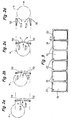
- Fig.2a-2d Draufsichten auf den Faßzentrierungs- und Auslösemechanismus der Etikettieranlage nach Fig. 1 bzw. 1a in verschiedenen Betriebszuständen,
- Fig. 3 eine Draufsicht auf ein Etikettenband.
- 1 shows the essential components of a labeling system for automatic drum labeling with a labeling device according to the invention,
- 1a shows a labeling system with a labeling device modified compared to FIG. 1,
- 2a-2d top views of the drum centering and triggering mechanism of the labeling system according to FIGS. 1 and 1a in different operating states,
- Fig. 3 is a plan view of a label tape.
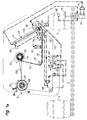
Die in der Zeichnung schematisch dargestellten Etikettieranlagen bestehen im wesentlichen aus einer über einer Förderbahn 2 für den Transport der zu etikettierenden Gegenstände 4 angeordneten Etikettiervorrichtung 6, in der mit Hilfe eines pneumatisch arbeitenden Vorzugmechanismus 8 ein Selbstklebeetiketten 10 tragendes Etikettenband 12 von einer Vorrats- und Abzugsrolle 14 abgezogen, an einem pneumatisch betätigten Druckwerk 16, einer Abtasteinrichtung 18, einer Spendekante 20 und einem pneumatisch betätigten Andrückmechanismus 22 vorbeigezogen und auf einer Aufwickelrolle 23 aufgewickelt wird. Die Auslösung des Etikettiervorgangs einschließlich Bandvorzug und Druckvorgang erfolgt über einen durch die zu etikettierenden Gegenstände mechanisch betätigten Auslösemechanismus 24, der im Bereich der Förderbahn 2 angeordnet ist.The labeling systems shown schematically in the drawing essentially consist of a labeling device 6 arranged above a
In dem gezeigten Ausführungsbeispiel sind die zu etikettierenden Gegenstände Bierfässer 4, die aufrecht auf einer Röllchenbahn 2 transportiert werden und die an ihrem Deckel möglichst punktgenau neben dem Spundloch etikettiert werden sollen.In the exemplary embodiment shown, the objects to be labeled are
Das von der Abzugsrolle 14 kommende Etikettenband 12 gelangt über eine Umlenkrolle 26 und durch die Druckstation 16 zu der Abtasteinrichtung 18, die aus einer Luftschranke besteht, bei der eine Sendedüse 28 und eine Empfängerdüse 30 einander gegenüberliegend auf einem gabelförmigen Teil angeordnet sind. Um von der Luftschranke abgetastet werden zu können, weist das Etikettenband 12 im Etikettenabstand Löcher 32 auf, wie in Fig. 3 dargestellt ist. Der Vorzug des Etikettenbandes erfolgt schrittweise, wobei die Schrittweite normalerweise über die Abtasteinrichtung 18 durch Abtastung der Löcher 32 gesteuert wird.The
In Vorzugrichtung hinter der Abtasteinrichtung 18 gelangt das Etikettenband 12 mit nach oben weisenden Selbstklebeetiketten 10 zu der scharfkantigen Spendekante 20, an der es so umgelenkt wird, daß das zuvordert auf dem Etikettenband 12 angeordnete Selbstklebeetikett 10'von der Unterlage abgelöst und noch ein Stück weit über die Spendekante 20 nach vorn geschoben wird, während das leere Etikettenband 12' im spitzen Winkel nach unten gezogen wird. Das freiwerdende Selbstklebeetikett 10' wird über Saugluftöffnungen in der freien Unterfläche des Stempels 40 des Andrückmechanismus 22 angesaugt und dort durch die Saugwirkung festgehalten. Der Stempel 40 ist am Ende einer Kolbenstange 42 eines relativ langen Pneumatikzylinders 44 angeordnet.In the preferred direction behind the
Der Vorzugsmechanismus 8 enthält eine mittels eines Pneumatikzylinders 46 in Richtung des Doppelpfeils 48 vor- und zurückverschiebbare pneumatische Bandklemmeinrichtung 50, die so angesteuert wird, daß sie bei der Vorwärtsbewegung das leere Etikettenband 12' durch Andrücken der Klemmpratze 52 festhält und mitnimmt, während sie beim Zurückbewegen geöffnet ist. Der Vorzugweg des Etikettenbands 12 wird normalerweise über die Abtasteinrichtung 18 gesteuert, die bei Vorhandensein eines Loches 32 im Etikettenband 12 ein Signal zum Öffnen der Bandklemmeneinrichtung 50 abgibt. Bei der Herstellung von Etikettenbändern kommt es erfahrungsgemäß immer wieder vor, daß vereinzelt Löcher 32 nicht ober nicht vollständig durchgestanzt sind und dadurch von der Abtasteinrichtung 18 nicht erfaßt werden. Um auch in solchen Fällen Betriebsstörungen zu vermeiden, ist zusätzlich ein redundantes pneumatisches Endschaltventil 54 vorhanden, das unmittelbar durch die Bandklemmeinrichtung 50 mechanisch betätigbar ist und das nach Erreichen eines einstellbaren Vorschubwegs die Bandklemmeinrichtung 50 umsteuert. Die Ausgangssignale des Endschaltventils 54 und der Abtasteinrichtung 18 sind über eine ODER-Logik 56 miteinander verknüpft.The
Bei dem in Fig. 1 gezeigten Ausführungsbeispiel befindet sich in Vorzugrichtung hinter der verschiebbaren Bandklemmeinrichtung 50 eine im Gegentakt zu dieser betätigbare ortsfeste Bandklemmeinrichtung 58, die dafür sorgen soll, daß das leere Etikettenband 12' beim Vorziehen frei zur Aufwickelrolle 23 gelangt und beim Zurückverschieben der beweglichen Bandklemmeinrichtung 50 nicht ungewollt von dieser wieder mitgenommen wird. Die Symbole S und O kennzeichnen die Eingänge für das Schließen bzw. Öffnen der beiden Bandklemmeinrichtungen 50 und 58 und der beiden unten erläuterten Zentrierschranken 70.In the exemplary embodiment shown in FIG. 1, in the preferred direction, behind the displaceable
Beim Betrieb mit Selbstklebeetiketten 10 werden unvermeidlich Kleberspuren vom leeren Etikettenband 12' auf die Klemmbacken der Bandklemmeinrichtungen 50, 58 übertragen, die sich dort allmählich ansammeln und zu Hafterscheinungen zwischen den Klemmbacken und dem leeren Etikettenband 12' führen. Während sich aber die bewegliche Bandklemmeinrichtung 50 beim Zurückbewegen von dem eventuell anhaftenden leeren Etikettenband 12' aus eigener Kraft losreißen kann, ist dies bei der ortsfesten Bandklemmeinrichtung 58 nicht ohne weiteres der Fall, so daß es dort beim Bandvorschub infolge der Biegeschlaffheit des leeren Etikettenbandes 12' leicht zu einem Bandstau und damit zu folgeschweren Betriebsstörungen kommen kann.When operating with self-
Um derartige Betriebsstörungen zu vermeiden, wird bei der in Fig. 1a gezeigten Etikettiervorrichtung die stationäre Bandklemmeinrichtung 58 weggelassen. Statt dessen ist an der Aufwickelrolle 23 eine Rücklaufsperre 82, 83 vorgesehen, die dafür sorgt, daß das auf der Aufwickelrolle 23 aufgewickelte leere Etikettenband 12' nicht wieder abgezogen werden kann. In Fig. 1a ist die Rücklaufsperre der Einfachheit halber als in eine Umfangszahnung 82 der Aufwickelrolle 23 einrastende federbelastete Sperrklinke 83 angedeutet. Zweckmäßiger wird als Rücklaufsperre jedoch ein nicht gezeigter Freilauf verwendet, der eine stufenlose Aufwicklung ermöglicht.In order to avoid such malfunctions, the stationary
Ein weiterer Unterschied zwischen den in Fig. 1 und 1 gezeigten Ausführungsbeispielen besteht in der Art der Umsteuerung der beweglichen Bandklemmeinrichtung 50: Während im Falle der Fig. 1 die Umsteuerung der Bewegungsrichtung gleichzeitig mit dem Öffnen der Bandklemmeinrichtung 50 über das Ausgangssignal des ODER-Glieds 56 ausgelöst wird, erfolgt im Falle der Fig. 1a die Umsteuerung der Bewegungsrichtung allein über das Ausgangssignal des Endschaltventils 54, nachdem die Bandklemmeinrichtung 50 im Normalfall kurz zuvor über die Abtasteinrichtung 18 durch Ansteuerung über das ODER-Glied 56 geöffnet und damit der Bandvorzug unterbrochen worden ist. Mit der letztgenannten Anordnung erhält man eine zuverlässige Schaltfolge bei der Umsteuerung. In beiden Fällen ist der Vorschubweg der beweglichen Bandklemmeinrichtung 50 bis zum Endschaltventil 54 geringfügig größer einzustellen als der Etikettenabstand auf dem Etikettenband 12.Another difference between the exemplary embodiments shown in FIGS. 1 and 1 lies in the type of reversal of the movable belt clamping device 50: While in the case of FIG. 1, the reversal of the direction of movement simultaneously with the opening of the
Die Abzugsrolle 14 wird in Richtung des Pfeils 60 weitgehend schlupffrei über das durch den Vorzugmechanismus 8 abgezogene Etikettenband 12 angetrieben. Sie ist über eine nicht dargestellte Rutschnabe mit der Riemenscheibe 64 gekuppelt, die ihrerseits über einen Riementrieb 63 mit der Riemenscheibe 66 der Aufwickelrolle 23 so verbunden ist, daß die Aufwickelrolle 23 in Richtung des Pfeils 62 angetrieben wird. Die durch die unterschiedlichen Durchmesser der Riemenscheiben 64 und 66 definierte Übersetzung ist so gewählt, daß auch die leere Aufwickelrolle 23 bei voller Abzugsrolle 14 mit der für ein strammes Aufwickeln notwendigen Winkelgeschwindigkeit angetrieben wird. Im übrigen sorgt die vorgenannte Rutschnabe dafür, daß beim Aufwickeln ständig eine gewisse Bandspannung aufrechterhalten wird.The take-
Der Etikettiervorgang wird über zwei durch die Symbole A und B gekennzeichnete Schaltventile des Auslösemechanismus 24 ausgelöst, die mittels zweier seitlich in die Röllchenbahn 2 eingreifender, an Zentrierschranken 70 angelenkter und durch ein auf der angetriebenen Röllchenbahn 2 ankommendes Faß 4 gegen die Zentrierschranken schwenkbarer Hebel 72A, 72B betätigbar sind. Das UND-Glied 74 bewirkt, daß der Etikettiervorgang erst ausgelöst wird, wenn beide Schaltventile A, B gleichzeitig betätigt sind, was bedeutet, daß das Faß 4 richtig zentriert ist (s. Fig. 2a-2c). Danach wird zunächst der Stempel 40 durch Verschieben der Kolbenstange 42 schräg nach unten bewegt, bis er mit seiner das Selbstklebeetikett 10' tragenden Unterfläche gegen den Faßdeckel anschlägt. Um sich beim Andrücken an eine Neigung oder Wölbung des Faßdeckels anpassen zu können, ist der Stempel 40 an einer Querachse der Kolbenstange 42 angelenkt und über mehrere unabhängig voneinander zusammendrückbare oder dehnbare Schraubenfedern 41 mit dieser verbunden und besteht in seinem unteren Teil aus einem elastischen Werkstoff, beispielsweise aus Schaumgummi. Sobald der erwünschte Anpreßdruck erreicht ist, der an einem mit dem Innendruck des Pneumatikzylinders 44 beaufschlagten Druckschaltventil 76 eingestellt wird, wird der Stempel 40 wieder in seine Ausgangsstellung zurückgezogen, während das Selbstklebeetikett 10' auf dem Faßdekkel haften bleibt. In seiner oberen Endstellung betätigt der Stempel 40 über ein damit verbundenes Organ ein Schaltventil 78, über das sowohl die Zentrierschranken 70 als auch der Pneumatikzylinder 46 und die Bandklemmeinrichtung 50 des Vorzugmechanismus 8 sowie, im Falle der Fig. 1, die Bandklemmeinrichtung 58 angesteuert werden. Dabei wird das etikettierte Faß 4 durch Öffnen der Zentrierschranken 70 für den Weitertransport freigegeben (s. Fig. 2d). Das erneute Schließen der Zentrierschranken 70 wird über eine Lichtschranke 80 ausgelöst, die ein Signal abgibt, wenn das etikettierte Faß 4 den Bereich der Zentrierschranken 70 verlassen hat. Weiter wird das Etikettenband 12 um einen Lochabstand unter Ablösen eines neuen Selbstklebeetiketts 10' für den Stempel 40 vorgezogen. Anschließend wird das unter das Druckwerk 16 gelangte Selbstklebeetikett 10 bedruckt. Die Anlage ist sodann für einen weiteren Etikettiervorgang bereit, der durch das nächste Faß 4 ausgelöst wird.The labeling process is triggered by two switching valves of the
Claims (10)
Priority Applications (1)
| Application Number | Priority Date | Filing Date | Title |
|---|---|---|---|
| AT80101053T ATE284T1 (en) | 1979-03-12 | 1980-03-03 | LABELING DEVICE. |
Applications Claiming Priority (2)
| Application Number | Priority Date | Filing Date | Title |
|---|---|---|---|
| DE19792909655 DE2909655A1 (en) | 1977-05-04 | 1979-03-12 | LABELING DEVICE |
| DE2909655 | 1979-03-12 |
Publications (2)
| Publication Number | Publication Date |
|---|---|
| EP0015529A1 EP0015529A1 (en) | 1980-09-17 |
| EP0015529B1 true EP0015529B1 (en) | 1981-10-14 |
Family
ID=6065153
Family Applications (1)
| Application Number | Title | Priority Date | Filing Date |
|---|---|---|---|
| EP80101053A Expired EP0015529B1 (en) | 1979-03-12 | 1980-03-03 | Labelling apparatus |
Country Status (4)
| Country | Link |
|---|---|
| US (1) | US4270968A (en) |
| EP (1) | EP0015529B1 (en) |
| AT (1) | ATE284T1 (en) |
| DE (1) | DE3060034D1 (en) |
Families Citing this family (14)
| Publication number | Priority date | Publication date | Assignee | Title |
|---|---|---|---|---|
| US4427484A (en) | 1982-07-29 | 1984-01-24 | Camtron Systems, Inc. | Automatic labeling system |
| JPS5974040A (en) * | 1982-10-08 | 1984-04-26 | 大日本印刷株式会社 | Method and device for pasting label |
| US4869775A (en) * | 1988-04-26 | 1989-09-26 | Quittner John P | Tab depositing dispenser |
| US5370754A (en) * | 1991-06-27 | 1994-12-06 | Pfizer Inc. | Automatic motorless label applying system |
| US5188696A (en) * | 1991-07-31 | 1993-02-23 | Good Jr Kenneth W | Wrap around labeling machine |
| US5232540A (en) * | 1991-09-30 | 1993-08-03 | Ithaca Industries, Inc. | Automatic labeling machine and method |
| US5304264A (en) * | 1991-11-05 | 1994-04-19 | Automated Packaging Systems, Inc. | Item applicator and method |
| US5277741A (en) * | 1992-08-06 | 1994-01-11 | Bartlett Tool And Manufacturing, Inc. | Sealing apparatus |
| US5466328A (en) * | 1992-08-31 | 1995-11-14 | Fuji Xerox Co., Ltd. | Recorded sheet processing unit for image forming apparatus |
| JP2540824Y2 (en) * | 1992-10-08 | 1997-07-09 | 株式会社サトー | Label pitch switching device for label pasting machines |
| DE9407305U1 (en) * | 1994-05-02 | 1994-09-22 | Czewo Plast Kunststofftech | Device for delivering order material |
| US5849143A (en) * | 1997-04-18 | 1998-12-15 | Booth Manufacturing Company | Precision label application |
| US7328543B2 (en) * | 2006-05-17 | 2008-02-12 | Plitek, L.L.C. | Apparatus and method for the application of pressure relief valves |
| TWI557030B (en) * | 2014-07-30 | 2016-11-11 | 迅智自動化科技股份有限公司 | Labeling machine |
Family Cites Families (6)
| Publication number | Priority date | Publication date | Assignee | Title |
|---|---|---|---|---|
| US2920780A (en) * | 1956-10-01 | 1960-01-12 | Western Electric Co | Apparatus for applying pressure sensitive adhesive labels to articles |
| US3779829A (en) * | 1972-01-24 | 1973-12-18 | Njm Inc | Labeling machine |
| US3953278A (en) * | 1974-11-04 | 1976-04-27 | J. P. Stevens & Co., Inc. | Sticker applicator |
| US4019935A (en) * | 1975-05-14 | 1977-04-26 | Diamond International Corporation | Automatic feeding of labels for application to bottles or other containers |
| DE2719957C3 (en) * | 1977-05-04 | 1982-02-11 | Etifix Gebr. Dudzik, 7441 Neckartailfingen | Labeling device |
| US4188252A (en) * | 1977-08-31 | 1980-02-12 | Automecha Ltd. | Label positioning and applying apparatus |
-
1980
- 1980-03-03 DE DE8080101053T patent/DE3060034D1/en not_active Expired
- 1980-03-03 AT AT80101053T patent/ATE284T1/en not_active IP Right Cessation
- 1980-03-03 EP EP80101053A patent/EP0015529B1/en not_active Expired
- 1980-06-02 US US06/127,313 patent/US4270968A/en not_active Expired - Lifetime
Also Published As
| Publication number | Publication date |
|---|---|
| DE3060034D1 (en) | 1981-12-24 |
| EP0015529A1 (en) | 1980-09-17 |
| US4270968A (en) | 1981-06-02 |
| ATE284T1 (en) | 1981-10-15 |
Similar Documents
| Publication | Publication Date | Title |
|---|---|---|
| EP0015529B1 (en) | Labelling apparatus | |
| DE2427324C2 (en) | Machine for the optional processing of article cards | |
| CH646394A5 (en) | DEVICE FOR JOINTLY JOINING TWO FLEXIBLE MATERIAL TAPES, ESPECIALLY IN PACKAGING MACHINES. | |
| DE1910157B2 (en) | ||
| DE2710605C2 (en) | Labeling machine | |
| DE3215288C2 (en) | ||
| EP0248375A1 (en) | Method and device for dispensing labels adhering to a carrier strip | |
| DE2217032C3 (en) | Device for applying blanks made from a continuous web to objects | |
| EP0006179A1 (en) | Advancing device for a label backing strip | |
| DE2410332A1 (en) | Bag and tube closing system - uses clips in strip fed off roll in synchronism with punch operation | |
| DE2258612A1 (en) | LABELING MACHINE | |
| DE3310839C2 (en) | ||
| DE2909655A1 (en) | LABELING DEVICE | |
| DE2719957C3 (en) | Labeling device | |
| DE2858372C2 (en) | ||
| DE2837164A1 (en) | Packet banding machine with welding mechanism - has locking mechanism preventing reversing of driving members when tightening band | |
| DE4132369A1 (en) | DEVICE FOR PRINTING AND DISPENSING LABELS STICKING ON A STRIP OF MATERIAL | |
| DE3049248C2 (en) | Labeling device | |
| DE69815717T2 (en) | DEVICE AND METHOD FOR ATTACHING OBJECTS TO PRODUCTS | |
| EP0123097A1 (en) | Method for the semi-automatic or automatic labelling of articles, and labelling device for the realisation of this method | |
| DE1094445B (en) | Device for winding up smoothly coated webs of material, in particular made of thermoplastics | |
| US3626657A (en) | Tying mechanism for bails and the like | |
| DE1923994B1 (en) | Device for the cyclical advancement of a carrier tape, which is fitted with removable self-adhesive labels at intervals | |
| DE3818793A1 (en) | DEVICE FOR ALIGNING AND OPENING LAYING PLASTIC BAGS | |
| DE2021994C (en) | Label feeding device |
Legal Events
| Date | Code | Title | Description |
|---|---|---|---|
| PUAI | Public reference made under article 153(3) epc to a published international application that has entered the european phase |
Free format text: ORIGINAL CODE: 0009012 |
|
| AK | Designated contracting states |
Designated state(s): AT BE CH DE FR GB IT NL SE |
|
| 17P | Request for examination filed | ||
| ITF | It: translation for a ep patent filed |
Owner name: BARZANO' E ZANARDO MILANO S.P.A. |
|
| GRAA | (expected) grant |
Free format text: ORIGINAL CODE: 0009210 |
|
| AK | Designated contracting states |
Designated state(s): AT BE CH DE FR GB IT NL SE |
|
| REF | Corresponds to: |
Ref document number: 284 Country of ref document: AT Date of ref document: 19811015 Kind code of ref document: T |
|
| REF | Corresponds to: |
Ref document number: 3060034 Country of ref document: DE Date of ref document: 19811224 |
|
| ITTA | It: last paid annual fee | ||
| EAL | Se: european patent in force in sweden |
Ref document number: 80101053.9 |
|
| PGFP | Annual fee paid to national office [announced via postgrant information from national office to epo] |
Ref country code: DE Payment date: 19950325 Year of fee payment: 16 |
|
| PGFP | Annual fee paid to national office [announced via postgrant information from national office to epo] |
Ref country code: NL Payment date: 19950331 Year of fee payment: 16 |
|
| PGFP | Annual fee paid to national office [announced via postgrant information from national office to epo] |
Ref country code: FR Payment date: 19950410 Year of fee payment: 16 |
|
| PGFP | Annual fee paid to national office [announced via postgrant information from national office to epo] |
Ref country code: GB Payment date: 19950413 Year of fee payment: 16 |
|
| PGFP | Annual fee paid to national office [announced via postgrant information from national office to epo] |
Ref country code: AT Payment date: 19950414 Year of fee payment: 16 |
|
| PGFP | Annual fee paid to national office [announced via postgrant information from national office to epo] |
Ref country code: SE Payment date: 19950418 Year of fee payment: 16 |
|
| PGFP | Annual fee paid to national office [announced via postgrant information from national office to epo] |
Ref country code: CH Payment date: 19950421 Year of fee payment: 16 |
|
| PGFP | Annual fee paid to national office [announced via postgrant information from national office to epo] |
Ref country code: BE Payment date: 19950428 Year of fee payment: 16 |
|
| PG25 | Lapsed in a contracting state [announced via postgrant information from national office to epo] |
Ref country code: GB Effective date: 19960303 Ref country code: AT Effective date: 19960303 |
|
| PG25 | Lapsed in a contracting state [announced via postgrant information from national office to epo] |
Ref country code: SE Effective date: 19960304 |
|
| PG25 | Lapsed in a contracting state [announced via postgrant information from national office to epo] |
Ref country code: CH Effective date: 19960331 Ref country code: BE Effective date: 19960331 |
|
| BERE | Be: lapsed |
Owner name: J. U. W. DUDZIK 0HG Effective date: 19960331 |
|
| PG25 | Lapsed in a contracting state [announced via postgrant information from national office to epo] |
Ref country code: NL Effective date: 19961001 |
|
| GBPC | Gb: european patent ceased through non-payment of renewal fee |
Effective date: 19960303 |
|
| REG | Reference to a national code |
Ref country code: CH Ref legal event code: PL |
|
| PG25 | Lapsed in a contracting state [announced via postgrant information from national office to epo] |
Ref country code: FR Effective date: 19961129 |
|
| NLV4 | Nl: lapsed or anulled due to non-payment of the annual fee |
Effective date: 19961001 |
|
| PG25 | Lapsed in a contracting state [announced via postgrant information from national office to epo] |
Ref country code: DE Effective date: 19961203 |
|
| EUG | Se: european patent has lapsed |
Ref document number: 80101053.9 |
|
| REG | Reference to a national code |
Ref country code: FR Ref legal event code: ST |
|
| PLBE | No opposition filed within time limit |
Free format text: ORIGINAL CODE: 0009261 |
|
| STAA | Information on the status of an ep patent application or granted ep patent |
Free format text: STATUS: NO OPPOSITION FILED WITHIN TIME LIMIT |