EP0014918B1 - Dispositif destiné à déposer sur un support des gouttes d'encre - Google Patents
Dispositif destiné à déposer sur un support des gouttes d'encre Download PDFInfo
- Publication number
- EP0014918B1 EP0014918B1 EP80100647A EP80100647A EP0014918B1 EP 0014918 B1 EP0014918 B1 EP 0014918B1 EP 80100647 A EP80100647 A EP 80100647A EP 80100647 A EP80100647 A EP 80100647A EP 0014918 B1 EP0014918 B1 EP 0014918B1
- Authority
- EP
- European Patent Office
- Prior art keywords
- ink
- plate
- layer
- holes
- photoconductive
- Prior art date
- Legal status (The legal status is an assumption and is not a legal conclusion. Google has not performed a legal analysis and makes no representation as to the accuracy of the status listed.)
- Expired
Links
Images


Classifications
-
- B—PERFORMING OPERATIONS; TRANSPORTING
- B41—PRINTING; LINING MACHINES; TYPEWRITERS; STAMPS
- B41J—TYPEWRITERS; SELECTIVE PRINTING MECHANISMS, i.e. MECHANISMS PRINTING OTHERWISE THAN FROM A FORME; CORRECTION OF TYPOGRAPHICAL ERRORS
- B41J2/00—Typewriters or selective printing mechanisms characterised by the printing or marking process for which they are designed
- B41J2/005—Typewriters or selective printing mechanisms characterised by the printing or marking process for which they are designed characterised by bringing liquid or particles selectively into contact with a printing material
- B41J2/01—Ink jet
- B41J2/135—Nozzles
- B41J2/145—Arrangement thereof
- B41J2/155—Arrangement thereof for line printing
-
- B—PERFORMING OPERATIONS; TRANSPORTING
- B41—PRINTING; LINING MACHINES; TYPEWRITERS; STAMPS
- B41J—TYPEWRITERS; SELECTIVE PRINTING MECHANISMS, i.e. MECHANISMS PRINTING OTHERWISE THAN FROM A FORME; CORRECTION OF TYPOGRAPHICAL ERRORS
- B41J2/00—Typewriters or selective printing mechanisms characterised by the printing or marking process for which they are designed
- B41J2/005—Typewriters or selective printing mechanisms characterised by the printing or marking process for which they are designed characterised by bringing liquid or particles selectively into contact with a printing material
- B41J2/01—Ink jet
- B41J2/135—Nozzles
- B41J2/14—Structure thereof only for on-demand ink jet heads
- B41J2/14016—Structure of bubble jet print heads
- B41J2/14088—Structure of heating means
- B41J2/14104—Laser or electron beam heating the ink
Definitions
- the present invention relates to a device intended for depositing ink drops on a support and in particular an apparatus used for printing graphics on a support of limited dimensions such as postal items, tickets or labels.
- Ink jet or droplet machines are known in which the ink is in equilibrium at the ejection orifice under the action of the hydrostatic pressure and the surface tension of the ink.
- the ejection of the drop of ink from the orifice is obtained from a chamber containing ink and limited by two plates, one of which has the ejection holes.
- the two plates are subjected to an electrical potential difference and the plate having no holes is crossed by laser radiation.
- the ink subjected to an electrostatic field comprises photoconductive pigments which move towards the plate having holes.
- the device used requires the presence of photoconductive pigments, that is to say very fine particles dispersed in the ink.
- the phenomena involved are exclusively of an electrostatic nature, the effect of light on the photoconductive pigments triggering the movement of the particles.
- the device only works if, in the absence of a laser beam, the ink is retained by a very low capillary force. Then the slightest shock can cause an inadvertent ejection of ink.
- Document US-A 3,582,954 discloses a device making it possible to deposit ink drops on a support so as to form on this support by mosaics of graphics dots, comprising a regularly perforated plate opposite said support and a second plate substantially parallel to the first plate and having a layer of photoconductive material, the space between the plates defining a chamber containing the ink to be deposited and comprising a radiation source making it possible to illuminate selected zones of said layer of material photoconductive to allow a selective acceleration of the ink contained in certain holes of the first plate with a view to the ejection of a drop towards said support.
- the means for selectively accelerating the ink contained in certain holes comprise a cathode ray tube whose electron beam is directed selectively over certain holes and gives the insulating ink in this zone an electrical charge. Thanks to this load and an acceleration potential applied to the hole openings and to the support, a drop is ejected from a selected hole when a mechanical shock is applied to the entire perforated plate. As in the previous case, the triggering of the ejection of the drops comes from a mechanical shock. Therefore, the device is very sensitive against parasitic shocks.
- the object of the invention is to remedy this drawback and to provide a more reliable and more robust device with regard to the triggering of the drops.
- the present invention relates to a device for depositing on a support drops of ink so as to form on this support by mosaics of dots graphics, comprising a plate regularly perforated opposite said support and a second plate substantially parallel to the first plate, and having a layer of photoconductive material, the space between the plates defining a chamber containing ink to be deposited, and comprising a radiation source making it possible to illuminate selected areas of said layer of photoconductive material to allow a selective acceleration of the ink in certain holes of the first plate with a view to ejecting a drop towards said support, characterized in that said second plate also comprises at least one electrically conductive layer, which is transparent and located next to said photoconductive layer directed towards said radiation source, and that a source of electric voltage that heating is applied to said electrically conductive layer and to another layer located on the opposite side of said photoconductive layer, and which produces an electric current between said two electrically conductive layers by the illuminated zones of said layer of photoconductive material, this electric current used to heat selected areas of the ink to a degree that
- the device according to FIG. 1 comprises a plate 1 which is pierced with a set of holes 4 and defines, with a rear plate 2, a chamber 3 containing ink to be deposited. A seal 6 is interposed between the two plates. A printing medium 5 is placed opposite the plate 1. The ink is brought to the device by a conduit 7 opening into the plate 2 at one end and connected by the other end to a reservoir, not shown. Chamber 3 is connected by holes 8 at ambient atmospheric pressure, and the ink is at an approximately constant level. The ink is maintained in the chamber 3 and in the holes 4 under the combined effect on the one hand of the pressure difference due to the difference in level between the free surface of the reservoir and the holes 4, on the other hand of the forces of capillarity.
- the shape of the outlet of the conduit 7 as well as its location in a hole in the plate 2 is only an example of embodiment. It can also be unblocked anywhere in the chamber 3 not occupied by other elements of the device.
- the ink passage section must however be sufficient to ensure the flow rate corresponding to the maximum rate of the ejected drops. It is possible, for example, to provide an ink inlet hole in the plate 1 or in the joint 6, to provide a supply by several conduits opening out at different locations in the chamber 3. It is also possible to provide between the reservoir and the chamber 3 a or several filters intended to stop the impurities likely to clog the orifices 4.
- the pressure in the chamber 3 varying with the drop in level of the reservoir following the consumption of the ink, it is possible to improve the device by inserting into the conduit 7 a pump with a pressure regulating system.
- the use of a pump also allows the use of filters with greater pressure drops, and therefore more efficient filtering.
- the ink can remain between the plates 1 and 2 by the sole effect of the surface tension, without requiring watertight walls closing the periphery of said chamber.
- the holes 8 intended for the evacuation of air or gas bubbles which may appear in the chamber 3 are located at the highest points of said chamber. This applies as well for the case of operation in a vertical position as shown in Figure 2 as for the case of operation in another position, horizontal for example.
- means make it possible to move all of the plates 1 and 2 relative to the support in one or two directions parallel to the plane of said plates.
- the integral plates 1 and 2 are connected to a frame by means of two or more deformable elements comprising leaf springs or spring rods and each allowing movement in a different direction of the printing device relative to the support.
- the movement of the device can be achieved by means of electromagnets, each of these electromagnets bringing the printing device into a position determined from among several possible positions according to the directions of movement.
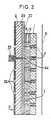
- FIG. 2 shows a variant of an electrically heated ejection device which may include a very large number of ejection holes.
- the plate 2 is covered with a layer 29 of electrically conductive material, the whole of the plate 2 with the layer 29 being transparent to electromagnetic radiation.
- This layer 29 is covered with a layer 30 of a photoconductive material whose electrical resistivity is greatly reduced, ie in a ratio of 1 to 10 for example, when it is illuminated with the aid of the aforementioned radiation.
- the ink contained in the chamber 3 is of the resistive type and the plate 1 is electrically conductive, or has a conductive layer on the side of the chamber 3, and is electrically insulated from the plate 2.
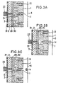
- FIGS. 3A, 3B, 3C represent three successive phases of the process of ejecting a drop of ink through a hole 11, forming part of the set of holes 4.
- the ink is suddenly heated in the vicinity of the hole 11.
- the heating of the ink by the electric current causes on the one hand a decrease in the viscosity and the surface tension of the ink, which decreases the energy required for ejection, and on the other hand, an early vaporization of the ink.
- This vaporization causes the growth of a gas bubble 13 which expels the ink in front of it through the hole 11, the pressure in the bubble increasing to overcome the forces opposing the movement of the ink, namely the surface tension, the viscosity and inertia of the ink.
- the increase in pressure is also transmitted by the ink contained in the chamber 3 to the hole 12 which must not eject a drop.
- the expansion of the gas bubble 13 causes the formation of a drop 14 as well as swelling of the meniscus towards the outside of the hole 12.
- the drop 14 is detached of the plate 1 and moves towards the support 5. Then, the heat source having been removed, the gas of the bubble condenses which causes a suction causing the meniscus to retreat inside the hole 11, of the ink then being sucked from the reservoir via the conduit 7 and from the chamber 3, under the effect of capillary forces, in order to compensate for the volume of ink of the ejected drop.
- the resistance to the passage of the ink along the path from 13 to 12 must be significantly higher than on the path from 13 to 11 , this being obtained by the choice of the shape and dimensions of the device by showing differences in the forces of inertia and viscosity according to the paths mentioned.
- this is achieved by choosing the ratio of the thickness of the chamber 3 to the spacing of the holes 4 sufficiently small. The upper limit of this ratio is approximately 1/2. This limit can however be exceeded if the ink used has a viscosity or a surface tension varying enough with temperature. In this case the ink in the hole 11 being sufficiently heated, its ejection is facilitated, while that in the hole 12 remaining at the initial temperature, can only be ejected by greater forces.
- a particular use of the devices described above consists in using an ink of very high viscosity or an ink solid at normal operating temperature.
- the sudden heating in the vicinity of the chosen ejection hole causes local liquefaction of the ink. Since the ink in the neighboring holes remains solid or viscous, there is no danger of ejection of unwanted drops therefrom.
- the surface of the support 5 is disposed far enough from the plate 1, so that the drops actually have room to form and move.
- the holes 4 of the plate 1 are preferably cylindrical because, in this case, their manufacture is generally easier. Their diameter cqndition the dimensions of the ejected drops and is preferably chosen between 10 microns and 100 microns. Economic drilling techniques for drilling large quantities of small holes are, for example, laser beam drilling, electron beam drilling, ultrasonic drilling or chemical etching. One can also manufacture the plate 1 with its holes by electro-chemical forming.
- Possible materials for plates 1 and 2 are for example stainless steel, glasses, nickel, alumina ceramics, tungsten, plastics.
- Figures 7 and 8 show a variant of the device, in which protrusions 15 have been brought to the plate 2 regularly distributed between the locations of the holes 4 in the plate 1 so as to oppose the movement of the ink between holes neighbors and thus avoid the ejection of unwanted drops as described above.
- These protuberances can be obtained by photogravures. They do not necessarily have to be of a height equal to the thickness of the chamber 3 as shown in FIG. 8. This arrangement has the advantage, however, of ensuring correct spacing of the plates 1 and 2.
- the protuberances 15 could also be taken in plate 1 instead of plate 2.
- the maximum ink flow rate circulating in the said chamber is also reduced, and we increase by therefore the maximum frequency of ejection.
- the resistivity of the ink must be adjusted to a value depending on the electrical voltage used, the dimensions of the device and the heating required for ejection.
- a mask 31 which is not essential for the functioning of the device, facilitates the control in position and in size of the region 34.
- This mask 31 consists of a layer of material opaque to the radiation used and in which openings 32 are formed facing each other. with respect to the holes 4 of the plate 1.
- the duration of the current pulse can be determined either by the duration of the beam 33 or by the duration of the electrical powering up of the layer 29 relative to the plate 1.
- Various means can be used to provide the beam 33.
- One means consists in using a laser beam deflected in the direction of the holes selected by movable mirrors or by acousto-optical or electro-optical processes known in the techniques for using laser rays.
- Another means consists in using an array of laser diodes or light-emitting diodes (LEDs), such that each hole 4 corresponds to a diode, or else such that, each diode corresponding to several holes 4, said array is movable relative to the plate 1 so as to cover all of the holes 4.
- Said network can be pressed directly against the plate 2 or the mask 31, or else be placed at a certain distance. It is also possible to interpose a suitable optical system between the array of diodes and the plate 2, for example Fresnel lenses, so as to form on the layer 30 an image if necessary reduced or enlarged of said array.
- Another means for supplying the beam 33 consists in placing a cover in front of the plate 2, this cover representing the pattern to be printed on the support 5 and in lighting the layer 30 through this cover by one or more lamps, for example lamps with incandescent, or fluorescent lamps, or electric gas discharge lamps.
- Said cover may include fixed parts, interchangeable or not, for printing possible constant parts of the pattern, and mobile parts, with automatic adjustment or not, for the variable parts of the pattern. It is also possible to use a liquid crystal matrix, or any other optical switch with electrical control, as a cover.
- the resistivity of the unlit photoconductive layer 30 must be sufficiently high compared to that of the ink used to ensure its isolation from the layer 29 and that the resistivity of the illuminated photoconductive layer 30 is rather weak compared to that of the ink so as to let the electric current pass.
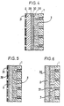
- FIG. 4 represents a variant of an ejection device comprising, as in FIG. 2, a photoconductive layer 30, this layer being in this case separated from the ink of the chamber 3 by an additional layer 35 of a material conducting the electricity whose resistivity and thickness are chosen so that the creation of heat by passage of the electric current takes place mainly in layer 35, or in layers 30 and 35.
- This arrangement has the advantage of widening the field of the possible values for the resistivity of the ink as well as to protect the layer 30 in the event of chemical incompatibility between the ink and the material of the layer 30.
- the layer 35 can also be made of a material which is a good conductor of the electricity, the electric voltage pulse being applied no longer between layer 29 and plate 1 as before, but between layers 29 and 35, the heat necessary for ejection is then generated exclusively in the neck che 30, such a device making it possible to use inks and materials for the plate 1 of any electrical resistivity.
- FIG. 5 represents another variant of a photoconductive ejection device in which the plate 2 itself is made of a photoconductive material, for example silicon and is covered with a layer of an electrically conductive material 36, on the side not bathed by the ink, this layer 36 being covered or not with the mask 31.
- the heating of the ink in this device is done in a manner analogous to the previous devices, the electric voltage being applied between the layer 36 and the plate 1 this plate being made of an electrically conductive material and the ink contained in the chamber 3 having an appropriate electrical resistivity so that the generation of heat takes place mainly in the ink, or in the plate 2, or in ink and in plate 2.
- the photoconductive material of the layer 30 of FIGS. 2 and 4 can for example be cadmium sulphide deposited in a few microns thick, the unlighted electrical resistivity of which is greater than 10 8 Ohm - cm and the illuminated resistivity of the order of 100 Ohm - centimeter.
- This material is sensitive to radiation with a wavelength of approximately 0.5 microns allowing the use of a plate 2 made of ordinary glass and a source of incandescent radiation.
- the thickness of the chamber 3 can be from 10 to 50 microns approximately, the ink having a resistivity of 500 Ohm - approximately centimeter. The electrical voltage used must then be of the order of 50 volts.
- the different variants of the ink drop ejection device described above are well suited for printing small graphics, for example 30 cm 2 , since the printing can then be carried out either without any relative movement of the device. printing relative to the printing medium, ie with only small amplitude displacements, for example 1 mm amplitude.
- These devices are more particularly suitable when the graphics have a constant part and a variable part, the constant part possibly being changed by exchanging a part or a set of parts of the device.
- variable part of these graphics can be. produced using a device according to any one of FIGS. 2 to 6, the constant part being able to be produced either in the same way, or preferably using simplified variants of the same devices.
- a first simplified variant consists in providing in the plate 1 only the holes corresponding to the mosaic representation of the constant graphics to be printed, as well as a complete network of holes in the area corresponding to the variable part of the graphics.
- the ejection through the holes of the constant graphics can then be controlled from a single electrode, or a single resistance, deposited on the plate 1 or the plate 2 and extending over the entire area corresponding to the set of these holes.
- a plate 1 normally pierced with a complete network of holes 4 corresponding to the variable and constant areas of the graphic, the printing of the constant part of the graphic being controlled using a single electrode consisting of a layer of electrically conductive material deposited on the plate 2, this layer itself being covered with an electrically insulating layer.
- the shape of the desired constant graphics is obtained by providing openings in the insulating layer, all of the openings forming the mosaic image of the desired graphics. The openings can be obtained by photochemical etching. If the plate 2 is made of an electrically conductive material, this serves as an electrode and the conductive layer is superfluous.
Description
- La présente invention concerne un dispositif destiné à déposer sur un support des gouttes d'encre et notamment un appareil servant à l'impression d'un graphisme sur un support de dimensions limitées telles que des objets postaux, des tickets ou des étiquettes.
- On connaît des machines à jet ou à gouttes d'encre dans lesquelles l'encre se trouve en équilibre à l'orifice d'éjection sous l'action de la pression hydrostatique et de la tension superficielle de l'encre. L'éjection de la goutte d'encre hors de l'orifice est obtenue à partir d'une chambre contenant de l'encre et limitée par deux plaques dont l'une comporte les trous d'éjection. Les deux plaques sont soumises à une différence de potentiel électrique et la plaque ne comportant pas de trous est traversée par un rayonnement laser. L'encre soumise à un champ électrostatique comporte des pigments photoconducteurs qui se déplacent vers la plaque comportant des trous. Cet état de la technique a été décrit dans l'article américain de XEROX DISCLOSURE JOURNAL vol. 1, n° 4 avril 1976 de D.L. CAMP-HAUSEN intitulé « Photoactivated ink spray page 75.
- Cependant le dispositif utilisé exige la présence de pigments photoconducteurs c'est-à-dire de très fines particules dispersées dans l'encre. De plus les phénomènes mis en jeu sont exclusivement de nature électrostatique, l'effet de la lumière sur les pigments photoconducteurs déclenchant le mouvement des particules.
- Comme les forces électrostatiques mises en jeu sont très faibles, le dispositif ne fonctionne que si, en l'absence de rayon laser, l'encre est retenue par une force de capillarité très faible. Alors le moindre choc peut provoquer une éjection intempestive d'encre.
- Par le document US-A 3 582 954, on connaît un dispositif permettant de déposer sur un support des gouttes d'encre de manière à former sur ce support par des mosaïques de points de graphismes, comportant une plaque régulièrement perforée en face dudit support et une deuxième plaque sensiblement parallèle à la première plaque et ayant une couche en matériau photoconducteur, l'espace entre les plaques définissant une chambre contenant l'encre à déposer et comportant une source de rayonnement permettant d'illuminer des zones sélectionnées de ladite couche en matériau photoconducteur pour permettre une accélération sélective de l'encre contenue dans certains trous de la première plaque en vue de l'éjection d'une goutte vers ledit support.
- Selon ce document, les moyens pour accélérer sélectivement l'encre contenue dans certains trous comportent un tube cathodique dont le faisceau électronique est dirigé sélectivement sur certains trous et donne à l'encre isolante dans cette zone une charge électrique. Grâce à cette charge et un potentiel d'accélération appliqué aux ouvertures des trous et au support, une goutte est éjectée d'un trou sélectionné lorsqu'un choc mécanique est appliqué à l'ensemble de la plaque perforée. Comme dans le cas précédent, le déclenchement de l'éjection des gouttes provient d'un choc mécanique. De ce fait, le dispositif est très sensible contre les chocs parasites.
- L'invention a pour but de remédier à cet inconvénient et de procurer un dispositif plus fiable et plus robuste en ce qui concerne le déclenchement des gouttes.
- La présente invention a pour objet un dispositif permettant de déposer sur un support des gouttes d'encre de manière à former sur ce support par des mosaïques de points des graphismes, comportant une plaque régulièrement perforée en face dudit support et une deuxième plaque sensiblement parallèle à la première plaque, et ayant une couche en matériau photoconducteur, l'espace entre les plaques définissant une chambre contenant de l'encre à déposer, et comportant une source de rayonnement permettant d'illuminer des zones sélectionnées de ladite couche en matériau photoconducteur pour permettre une accélération sélective de l'encre dans certains trous de la première plaque en vue de l'éjection d'une goutte vers ledit support, caractérisé par le fait que ladite deuxième plaque comporte également au moins une couche électriquement conductrice, qui est transparente et située à côté de ladite couche photoconductrice dirigé vers ladite source de rayonnement, et qu'une source de tension électrique de chauffage est appliquée à ladite couche électriquement conductrice et à une autre couche située au côté opposé de ladite couche photoconductrice, et qui produit un courant électrique entre lesdites deux couches électriquement conductrices par les zones illuminées de ladite couche en matériau photoconducteur, ce courant électrique servant à chauffer des zones sélectionnées de l'encre à un degré tel que l'encre soit éjectée par le trou ou les trous situés dans ces zones.
- En se référant aux figures schématiques 1 à 8 ci-jointes on va décrire ci-après un exemple de mise en oeuvre de la présente invention, exemple donné à titre purement illustratif et nullement limitatif. Les mêmes éléments représentés sur plusieurs de ces figures portent sur toutes celles-ci les mêmes références.
- La figure 1 est une vue très schématique en perspective éclatée d'un dispositif permettant d'appliquer l'invention.
- La figure 2 est une vue très agrandie en coupe verticale du même dispositif.
- Les figures 3A, 3B, 3C montrent le processus d'éjection d'une goutte.
- La figure 4 est la vue en coupe d'une portion d'un dispositif selon l'invention dans lequel une couche supplémentaire est disposée sur une couche photoconductrice.
- La figure 5 est la vue en coupe d'une portion d'un dispositif selon l'invention utilisant une plaque photoconductrice massive.
- La figure 6 est la vue en coupe d'une portion d'un dispositif selon l'invention utilisant une plaque photoconductrice recouverte d'une couche conductrice sur ses deux faces.
- Les figures 7 et 8 représentent une variante du dispositif dans laquelle des protubérances sont intercalées entre les trous d'éjection.
- Le dispositif selon la figure 1 comprend une plaque 1 qui est percée d'un ensemble de trous 4 et définit avec une plaque arrière 2 une chambre 3 contenant de l'encre à déposer. Un joint 6 est interposé entre les deux plaques. Un support d'impression 5 est placé face à la plaque 1. L'encre est amenée au dispositif par un conduit 7 débouchant dans la plaque 2 par une extrémité et relié par l'autre extrémité à un réservoir non représenté. La chambre 3 est reliée par des trous 8 à la pression atmosphérique ambiante, et l'encre est à un niveau approximativement constant. L'encre est maintenue dans la chambre 3 et dans les trous 4 sous l'effet combiné d'une part de la différence de pression due à la dénivellation entre la surface libre du réservoir et les trous 4, d'autre part des forces de capillarité.
- La forme du débouché du conduit 7 ainsi que sa localisation dans un trou ménagé dans la plaque 2 n'est qu'un exemple de réalisation. On peut aussi le faire déboucher en n'importe quel endroit de la chambre 3 non occupé par d'autres éléments du dispositif. La section de passage de l'encre doit cependant être suffisante pour assurer le débit correspondant à la cadence maximale des gouttes éjectées. On peut par exemple ménager un trou d'arrivée d'encre dans la plaque 1 ou dans le joint 6, prévoir une alimentation par plusieurs conduits débouchant en différents endroits de la chambre 3. On peut également prévoir entre le réservoir et la chambre 3 un ou plusieurs filtres destinés à arrêter les impuretés susceptibles d'obstruer les orifices 4.
- La pression dans la chambre 3 variant avec la baisse de niveau du réservoir consécutif à la consommation de l'encre, il est possible de perfectionner le dispositif par l'insertion dans le conduit 7 d'une pompe avec un système régulateur de pression. L'utilisation d'une pompe permet également l'usage de filtres présentant des pertes de charge plus importantes, et donc d'un filtrage plus efficace.
- Si l'épaisseur de la chambre 3 n'est pas trop grande, par exemple, inférieure ou égale à la moitié de l'entre-axe le plus faible des trous de la plaque 1, l'encre peut se maintenir entre les plaques 1 et 2 par le seul effet de la tension superficielle, sans nécessiter des parois étanches fermant la périphérie de ladite chambre. Les trous 8 destinés à l'évacuation des bulles d'air ou de gaz pouvant apparaître dans la chambre 3 sont situés aux points les plus hauts de ladite chambre. Cela vaut aussi bien pour le cas d'un fonctionnement en position verticale comme représenté sur la figure 2 que pour le cas d'un fonctionnement dans une autre position, horizontale par exemple.
- Pour imprimer un graphisme déterminé, on sélectionne certains de ces trous et on éjecte par chacun d'eux une goutte d'encre venant former un point à la surface du support 5, le graphisme désiré étant alors formé par une mosaïque de points. Si on veut améliorer la définition de cette mosaïque, on peut déplacer le dispositif par rapport au support 5 d'une distance égale à une fraction de l'espacement entre trous voisins et éjecter à nouveau des gouttes par certains des trous. On peut ainsi opérer plusieurs éjections de gouttes consécutives, chaque éjection étant précédée d'un déplacement du dispositif d'éjection par rapport au support 5, ces déplacements étant prévus de manière à ce que la matrice de points que l'on peut imprimer sur le support 5 comporte un nombre de points égal à plusieurs fois le nombre de trous 4 de la plaque 1.
- Pour cela, des moyens permettent de déplacer l'ensemble des plaques 1 et 2 par rapport au support suivant une ou deux directions parallèles au plan desdites plaques. Les plaques solidaires 1 et 2 sont reliées à un bâti par l'intermédiaire de deux ou plusieurs éléments déformables comportant des lames ressorts ou des tiges ressorts et permettant chacun un déplacement dans une direction différente du dispositif d'impression par rapport au support. Le déplacement du dispositif peut être réalisé au moyen d'électro-aimants, chacun de ces électro-aimants amenant le dispositif d'impression dans une position déterminée parmi plusieurs positions possibles suivant les directions de déplacement.
- La figure 2 représente une variante de dispositif d'éjection à chauffage électrique pouvant comporter un très grand nombre de trous d'éjection. Dans cette variante, la plaque 2 est recouverte d'une couche 29 de matériau conducteur de l'électricité, l'ensemble de la plaque 2 avec la couche 29 étant transparent à un rayonnement électromagnétique. Cette couche 29 est recouverte d'une couche 30 d'un matériau photoconducteur dont la résistivité électrique est diminuée fortement, soit dans un rapport de 1 à 10 par exemple, lorsqu'il est éclairé à l'aide du rayonnement précité. L'encre contenue dans la chambre 3 est de type résistif et la plaque 1 est électriquement conductrice, ou comporte une couche conductrice du côté de la chambre 3, et est isoléë électriquement de la plaque 2. Pour éjecter une goutte d'encre, on éclaire à travers la plaque 2 la région 34 de la couche photoconductrice 30 faisant face au trou sélectionné par un faisceau étroit 33 du rayonnement précité. Par suite la résistivité de la zone 34 diminue fortement, ce qui permet le passage d'une impulsion de courant électrique dans l'encre, si on applique une tension électrique entre la plaque 1 et la couche 29. L'éjection se produit ensuite comme représenté sur les figures 3A à 3C.
- Les figures 3A, 3B, 3C représentent trois phases successives du processus d'éjection d'une goutte d'encre par un trou 11, faisant partie de l'ensemble de trous 4. Pour provoquer l'éjection, on chauffe brutalement l'encre au voisinage du trou 11. L'échauffement de l'encre par le courant électrique provoque d'une part une diminution de la viscosité et de la tension superficielle de l'encre, ce qui fait décroître l'énergie requise pour l'éjection, et d'autre part, un début de vaporisation de l'encre. Cette vaporisation provoque la croissance d'une bulle de gaz 13 qui chasse l'encre devant elle par le trou 11, la pression dans la bulle augmentant pour vaincre les forces s'opposant au déplacement de l'encre, soit la tension superficielle, la viscosité et l'inertie de l'encre. L'augmentation de pression est également transmise par l'encre contenue dans la chambre 3 vers le trou 12 qui lui ne doit pas éjecter de goutte. Comme représenté sur la figure 4b, l'expansion de la bulle de gaz 13 provoque la formation d'une goutte 14 ainsi qu'un gonflement du ménisque vers l'extérieur du trou 12. Sur la figure 4c la goutte 14 s'est détachée de la plaque 1 et se déplace vers le support 5. Ensuite, la source de chaleur ayant été supprimée, le gaz de la bulle se condense ce qui provoque une aspiration faisant reculer le ménisque à l'intérieur du trou 11, de l'encre étant ensuite aspirée du réservoir par l'intermédiaire du conduit 7 et de la chambre 3, sous l'effet des forces capillaires, afin de compenser le volume d'encre de la goutte éjectée. Afin d'éviter l'éjection non désirée d'une goutte par un trou adjacent 12, il faut que la résistance au passage de l'encre le long du chemin de 13 à 12 soit nettement plus élevée que sur le chemin de 13 à 11, ceci étant obtenu par le choix de la forme et des dimensions du dispositif en faisant apparaître des différences dans les forces d'inertie et de viscosité selon les chemins mentionnés. Dans le dispositif de la figure 2 ceci est réalisé en choisissant le rapport de l'épaisseur de la chambre 3 à l'espacement des trous 4 suffisamment faible. La limite supérieure de ce rapport est d'environ 1/2. Cette limite peut cependant être dépassée si l'encre utilisée présente une viscosité ou une tension superficielle variant suffisamment avec la température. Dans ce cas l'encre se trouvant dans le trou 11 étant suffisamment échauffée, son éjection se trouve facilitée, alors que celle dans le trou 12 restant à la température initiale, ne peut être éjectée que par des forces plus importantes.
- Une utilisation particulière des dispositifs décrits ci-dessus consiste à utiliser une encre de très forte viscosité ou une encre solide à la température normale de fonctionnement. Dans ce cas, l'échauffement brutal au voisinage du trou d'éjection choisi provoque une liquéfaction locale de l'encre. L'encre dans les trous voisins restant solide ou visqueuse, les dangers d'éjection de gouttes indésirées par ceux-ci sont nuls.
- Dans l'éjection telle que décrite sur les figures 3A, 3B, 3C, la surface du support 5 est disposée assez loin de la plaque 1, de telle manière que les gouttes aient effectivement la place de se former et de se déplacer.
- Dans le cas de fonctionnement avec de l'encre solide comme expliqué précédemment, il est également possible d'appliquer le support 5 contre la plaque 1, la fusion de l'encre suffisant alors à assurer le marquage du point.
- Les trous 4 de la plaque 1 sont de préférence cylindriques car, dans ce cas, leur fabrication est en général plus facile. Leur diamètre cqnditionne les dimensions des gouttes éjectées et est choisi de préférence entre 10 microns et 100 microns. Des techniques de perçage économique permettant de percer de grandes quantités de trous de petite dimension sont, par exemple, le perçage par faisceau laser, le perçage par faisceau d'électrons, le perçage par ultrasons ou la gravure chimique. On peut également fabriquer la plaque 1 avec ses trous par formage électro-chimique.
- Des matériaux envisageables pour les plaques 1 et 2 sont par exemple l'acier inoxydable, les verres, le nickel, les céramiques d'alumine, le tungstène, des matières plastiques.
- Les figures 7 et 8 représentent une variante du dispositif, dans lequel on a fait venir sur la plaque 2 des protubérances 15 régulièrement réparties entre les emplacements des trous 4 de la plaque 1 de manière à s'opposer au déplacement de l'encre entre trous voisins et ainsi d'éviter l'éjection de gouttes indésirées comme décrit ci-dessus. Ces protubérances peuvent être obtenues par photogravures. Elles ne sont pas obligatoirement d'une hauteur égale à l'épaisseur de la chambre 3 comme représenté sur la figure 8. Cette disposition a cependant l'avantage d'assurer un espacement correct des plaques 1 et 2. Les protubérances 15 pourraient également être prises dans la plaque 1 au lieu de la plaque 2.
- En diminuant les sections de passage entre trous voisins, soit en diminuant l'épaisseur de la chambre 3, soit par un dispositif selon les figures 7 et 8, on diminue aussi le débit maximum d'encre circulant dans ladite chambre, et on augmente par conséquent la fréquence maximum d'éjection.
- La résistivité de l'encre doit être ajustée à une valeur dépendant de la tension électrique utilisée, des dimensions du dispositif et de l'échauffement requis pour l'éjection. On peut par exemple utiliser des encres comprenant une proportion importante d'eau et dont la résistivité est ajustée par addition de chlorure de sodium ou d'acide chlorhydrique. On peut ainsi obtenir des encres de résistivité comprise entre 50 Ohm - mètre et 0,05 Ohm - mètre.
- Un masque 31 non indispensable au fonctionnement du dispositif, facilite le contrôle en position et en dimension de la région 34. Ce masque 31 est constitué par une couche d'un matériau opaque au rayonnement utilisé et dans laquelle des ouvertures 32 sont ménagées en vis-à-vis des trous 4 de la plaque 1. La durée de l'impulsion de courant peut être déterminée soit par la durée du faisceau 33 soit par la durée de la mise sous tension électrique de la couche 29 par rapport à la plaque 1. Divers moyens peuvent être utilisés pour fournir le faisceau 33. Un moyen consiste à utiliser un rayon laser dévié en direction des trous sélectionnés par des miroirs mobiles ou par des procédés acousto-optiques ou électro-optiques connus dans les techniques d'utilisation des rayons laser. Un autre moyen consiste à utiliser un réseau de diodes laser ou de diodes électroluminescentes (LED), tel que à chaque trou 4 corresponde une diode, ou bien tel que, chaque diode correspondant à plusieurs trous 4, ledit réseau soit déplaçable par rapport à la plaque 1 de manière à recouvrir la totalité des trous 4. Ledit réseau peut être plaqué directement contre la plaque 2 ou le masque 31, ou bien être disposé à une certaine distance. On peut également intercaler un système optique convenable entre le réseau de diodes et la plaque 2, par exemple des lentilles de Fresnel, de manière à former sur la couche 30 une image si nécessaire réduite ou agrandie dudit réseau. Un autre moyen pour fournir le faisceau 33 consiste à disposer un cache devant la plaque 2, ce cache représentant le motif à imprimer sur le support 5 et à éclairer la couche 30 à travers ce cache par une ou plusieurs lampes, par exemple des lampes à incandescence, ou des lampes à fluorescence, ou des lampes à décharge électrique dans un gaz. Ledit cache peut comporter des parties fixes, interchangeables ou non, pour l'impression d'éventuelles parties constantes du motif, et des parties mobiles, à réglage automatique ou non, pour les parties variables du motif. On peut également utiliser comme cache une matrice à cristaux liquides, ou tout autre commutateur optique à commande électrique.
- Pour que le système fonctionne convenablement, il faut que la résistivité de la couche photoconductrice 30 non éclairée soit suffisamment élevée par rapport à celle de l'encre utilisée pour assurer l'isolement de celle-ci par rapport à la couche 29 et que la résistivité de la couche photoconductrice 30 éclairée soit assez faible par rapport à celle de l'encre de manière à laisser passer le courant électrique. On peut également utiliser une couche photoconductrice dont la résistivité sous éclairement est du même ordre de grandeur que celle de l'encre, auquel cas la couche photoconductrice 30 participe à l'échauffement en même temps que l'encre, la chaleur produite dans cette couche étant transmise à l'encre comme dans le cas d'utilisation d'une résistance chauffante. On peut même choisir la résistivité de la couche photoconductrice 30 éclairée assez grande pour que la chaleur engendrée par le courant électrique le soit essentiellement dans ladite couche.
- La figure 4 représente une variante de dispositif d'éjection comportant comme sur la figure 2 une couche photoconductrice 30, cette couche étant dans ce cas séparée de l'encre de la chambre 3 par une couche supplémentaire 35 d'un matériau conducteur de l'électricité dont la résistivité et l'épaisseur sont choisies de manière à ce que la création de chaleur par passage du courant électrique se fasse principalement dans la couche 35, ou dans les couches 30 et 35. Cette disposition présente l'avantage d'élargir le champ des valeurs possibles pour la résistivité de l'encre ainsi que de protéger la couche 30 en cas d'incompatibilité chimique entre l'encre et le matériau de la couche 30. La couche 35 peut également être en un matériau bon conducteur de l'électricité, l'impulsion de tension électrique étant appliquée non plus entre la couche 29 et la plaque 1 comme précédemment, mais entre les couches 29 et 35, la chaleur nécessaire à l'éjection étant alors engendrée exclusivement dans la couche 30, un tel dispositif permettant d'utiliser des encres et des matériaux pour la plaque 1 de résistivités électriques quelconques.
- La figure 5 représente une autre variante de dispositif d'éjection à photoconducteur dans lequel la plaque 2 elle-même est en un matériau photoconducteur, par exemple du silicium et est recouverte d'une couche d'un matériau conducteur de l'électricité 36, du côté non baigné par l'encre, cette couche 36 étant recouverte ou non du masque 31. L'échauffement de l'encre dans ce dispositif se fait d'une manière analogue aux dispositifs précédents, la tension électrique étant appliquée entre la couche 36 et la plaque 1 cette plaque étant en un matériau conducteur de l'électricité et l'encre contenue dans la chambre 3 ayant une résistivité électrique appropriée pour que la génération de chaleur ait lieu principalement dans l'encre, ou dans la plaque 2, ou dans l'encre et dans la plaque 2.
- On peut également recouvrir la face de la plaque 2 du côté de la chambre 3 d'une couche conductrice de l'électricité 37 comme représenté sur la figure 6. Dans ce cas on peut appliquer la tension électrique entre les couches 36 et 37, l'encre et le matériau de la plaque 1 pouvant avoir des résistivités électriques quelconques.
- Le matériau photoconducteur de la couche 30 des figures 2 et 4 peut par exemple être du sulfure de cadmium déposé en quelques microns d'épaisseur, dont la résistivité électrique non éclairée est plus grande que 108 Ohm - centimètre et la résistivité éclairée de l'ordre de 100 Ohm - centimètre. Ce matériau est sensible à un rayonnement de longueur d'onde d'environ 0,5 microns permettant l'usage d'une plaque 2 en verre ordinaire et d'une source de rayonnement à incandescence. L'épaisseur de la chambre 3 peut être de 10 à 50 microns environ, l'encre présentant une résistivité de 500 Ohm - centimètre environ. La tension électrique utilisée doit alors êtrë de l'ordre de 50 volts.
- Les différentes variantes de dispositif à éjection de gouttes d'encre décrites ci-dessus sont bien adaptées à l'impression de graphismes de faibles dimensions, par exemple 30 cm2, car l'impression peut alors être effectuée soit sans aucun déplacement relatif du dispositif d'impression par rapport au support d'impression, soit avec seulement des déplacements de faible amplitude, par exemple 1 mm d'amplitude. Ces dispositifs conviennent de plus particulièrement lorsque le graphisme comporte une partie constante et une partie variable, la partie constante pouvant éven- tuellementêtre changée par échange d'une pièce ou d'un ensemble de pièces du dispositif.
- La partie variable de ces graphismes peut être . réalisée à l'aide d'un dispositif selon l'une quelconque des figures 2 à 6, la partie constante pouvant être réalisée soit de la même manière, soit de préférence à l'aide de variantes simplifiées des mêmes dispositifs.
- Une première variante simplifiée consiste à ne prévoir dans la plaque 1 que les trous correspondant à la représentation mosaïque du graphisme constant à imprimer, ainsi qu'un réseau complet de trous dans la zone correspondant à la partie variable du graphisme. L'éjection par les trous du graphisme constant peut alors être commandée à partir d'une seule électrode, ou d'une seule résistance, déposée sur la plaque 1 ou la plaque 2 et s'étendant sur la totalité de la zone correspondant à l'ensemble de ces trous.
- Dans une deuxième variante simplifiée, on utilise une plaque 1 percée normalement d'un réseau de trous complet 4 correspondant aux zones variables et constantes du graphisme, l'impression de la partie constante du graphisme étant commandée à l'aide d'une électrode unique constituée d'une couche de matériau conducteur de l'électricité déposée sur la plaque 2, cette couche étant elle-même recouverte d'une couche électriquement isolante. La forme du graphisme constant désiré est obtenue en ménageant dans la couche isolante des ouvertures, l'ensemble des ouvertures formant l'image en mosaïque du graphisme désiré. Les ouvertures peuvent être obtenues par gravure photochimique. Si la plaque 2 est faite d'un matériau conducteur de l'électricité, celle-ci sert d'électrode et la couche conductrice est superflue.
- Encore une autre possibilité pour des graphismes constants consiste en un cache optique qui ne permet l'éclairage de la couche photoconductrice que par certaines zones.
Claims (7)
Priority Applications (1)
| Application Number | Priority Date | Filing Date | Title |
|---|---|---|---|
| AT80100647T ATE3833T1 (de) | 1979-02-16 | 1980-02-08 | Vorrichtung zum uebertragen von tintentroepfchen auf einen aufzeichnungstraeger. |
Applications Claiming Priority (2)
| Application Number | Priority Date | Filing Date | Title |
|---|---|---|---|
| FR7904012 | 1979-02-16 | ||
| FR7904012A FR2448979B1 (fr) | 1979-02-16 | 1979-02-16 | Dispositif destine a deposer sur un support des gouttes d'encre |
Publications (2)
| Publication Number | Publication Date |
|---|---|
| EP0014918A1 EP0014918A1 (fr) | 1980-09-03 |
| EP0014918B1 true EP0014918B1 (fr) | 1983-06-22 |
Family
ID=9222084
Family Applications (1)
| Application Number | Title | Priority Date | Filing Date |
|---|---|---|---|
| EP80100647A Expired EP0014918B1 (fr) | 1979-02-16 | 1980-02-08 | Dispositif destiné à déposer sur un support des gouttes d'encre |
Country Status (5)
| Country | Link |
|---|---|
| US (1) | US4312009A (fr) |
| EP (1) | EP0014918B1 (fr) |
| AT (1) | ATE3833T1 (fr) |
| DE (1) | DE3063802D1 (fr) |
| FR (1) | FR2448979B1 (fr) |
Families Citing this family (150)
| Publication number | Priority date | Publication date | Assignee | Title |
|---|---|---|---|---|
| DE3269768D1 (en) * | 1981-01-21 | 1986-04-17 | Matsushita Electric Ind Co Ltd | Ink jet printing head utilizing pressure and potential gradients |
| US4403228A (en) * | 1981-03-19 | 1983-09-06 | Matsushita Electric Industrial Company, Limited | Ink jet printing head having a plurality of nozzles |
| US4822418A (en) * | 1981-03-27 | 1989-04-18 | Dataproducts Corporation | Drop on demand ink jet ink comprising dubutyl sebecate |
| US4450455A (en) * | 1981-06-18 | 1984-05-22 | Canon Kabushiki Kaisha | Ink jet head |
| US4558333A (en) * | 1981-07-09 | 1985-12-10 | Canon Kabushiki Kaisha | Liquid jet recording head |
| DE3250114C2 (de) * | 1981-07-09 | 2000-03-02 | Canon Kk | Flüssigkeitsstrahl-Aufzeichnungskopf |
| GB2106039A (en) * | 1981-08-14 | 1983-04-07 | Hewlett Packard Co | Thermal ink jet printer |
| US4793264A (en) * | 1981-12-07 | 1988-12-27 | Dataproducts Corporation | Low corrosion impulse ink jet ink containing anti-oxidant |
| US5182572A (en) * | 1981-12-17 | 1993-01-26 | Dataproducts Corporation | Demand ink jet utilizing a phase change ink and method of operating |
| US4659383A (en) * | 1981-12-17 | 1987-04-21 | Exxon Printing Systems, Inc. | High molecular weight, hot melt impulse ink jet ink |
| US4758276A (en) * | 1981-12-17 | 1988-07-19 | Dataproducts Corporation | Stearic acid-containing ink jet inks |
| US4470055A (en) * | 1982-03-10 | 1984-09-04 | Fuji Xerox Co., Ltd. | Photo-thermal ink transferring device |
| JPS59165662A (ja) * | 1983-03-10 | 1984-09-18 | Fuji Xerox Co Ltd | インクジエツト噴射装置 |
| JPS59187870A (ja) * | 1983-04-08 | 1984-10-25 | Canon Inc | 液体噴射記録装置 |
| US4561789A (en) * | 1983-06-23 | 1985-12-31 | Nippon Telegraph & Telephone Public Corp. | Thermal ink transfer printing system |
| JPS6071260A (ja) * | 1983-09-28 | 1985-04-23 | Erumu:Kk | 記録装置 |
| US4546360A (en) * | 1983-12-16 | 1985-10-08 | Xerox Corporation | Electrothermic ink jet |
| US4607267A (en) * | 1983-12-19 | 1986-08-19 | Ricoh Company, Ltd. | Optical ink jet head for ink jet printer |
| USRE34029E (en) * | 1984-05-10 | 1992-08-11 | Willett International Limited | Method for applying a hot melt ink to a substrate |
| JPS6175227A (ja) * | 1984-09-20 | 1986-04-17 | Nippon Kokan Kk <Nkk> | 移動物体の温度測定装置 |
| US4667206A (en) * | 1984-10-15 | 1987-05-19 | Deyoung Thomas W | Ink jet apparatus and method of operating the ink jet apparatus wherein phase change ink is supplied in solid-state form |
| US4631557B1 (en) * | 1984-10-15 | 1997-12-16 | Data Products Corp | Ink jet employing phase change ink and method of operation |
| US5350446A (en) * | 1984-11-05 | 1994-09-27 | Dataproducts Corporation | Hot melt impulse ink jet ink with dispersed solid pigment in a hot melt vehicle |
| DE3573753D1 (en) * | 1985-03-27 | 1989-11-23 | Elm Corp | Thermal ink jet printer |
| DE3577674D1 (de) * | 1985-05-20 | 1990-06-21 | Elm Corp | Druckkopf. |
| EP0212943B1 (fr) * | 1985-08-13 | 1991-02-27 | Matsushita Electric Industrial Co., Ltd. | Dispositif d'impression par jet d'encre |
| DE3702643A1 (de) * | 1986-02-10 | 1987-08-13 | Toshiba Kawasaki Kk | Tintenstrahlschreiber sowie schreibkopf und schreibkopfkassette dafuer |
| US4931955A (en) * | 1987-04-28 | 1990-06-05 | Juki Corporation | Ink jet printing apparatus with preprinting jet purging mechanism |
| JPS63272558A (ja) * | 1987-04-30 | 1988-11-10 | Nec Corp | インクジェット記録装置 |
| US5189437A (en) * | 1987-09-19 | 1993-02-23 | Xaar Limited | Manufacture of nozzles for ink jet printers |
| US4882595A (en) * | 1987-10-30 | 1989-11-21 | Hewlett-Packard Company | Hydraulically tuned channel architecture |
| US4829319A (en) * | 1987-11-13 | 1989-05-09 | Hewlett-Packard Company | Plastic orifice plate for an ink jet printhead and method of manufacture |
| US4998120A (en) * | 1988-04-06 | 1991-03-05 | Seiko Epson Corporation | Hot melt ink jet printing apparatus |
| US5682187A (en) * | 1988-10-31 | 1997-10-28 | Canon Kabushiki Kaisha | Method for manufacturing an ink jet head having a treated surface, ink jet head made thereby, and ink jet apparatus having such head |
| US5208604A (en) * | 1988-10-31 | 1993-05-04 | Canon Kabushiki Kaisha | Ink jet head and manufacturing method thereof, and ink jet apparatus with ink jet head |
| US4949102A (en) * | 1989-05-30 | 1990-08-14 | Eastman Kodak Company | Bubble jet print head orifice construction |
| US5235350A (en) * | 1990-01-22 | 1993-08-10 | Dataproducts Corporation | Pigmented semiconductive hot melt ink and ink jet apparatus employing same |
| JP3032021B2 (ja) * | 1990-02-02 | 2000-04-10 | キヤノン株式会社 | インクジェット記録装置 |
| US5442384A (en) * | 1990-08-16 | 1995-08-15 | Hewlett-Packard Company | Integrated nozzle member and tab circuit for inkjet printhead |
| DE69111936T2 (de) * | 1990-08-16 | 1996-04-11 | Hewlett Packard Co | Photo-ablatierte Bauteile für Farbstrahldruckkopf. |
| US5291226A (en) * | 1990-08-16 | 1994-03-01 | Hewlett-Packard Company | Nozzle member including ink flow channels |
| US5469199A (en) * | 1990-08-16 | 1995-11-21 | Hewlett-Packard Company | Wide inkjet printhead |
| US5305015A (en) * | 1990-08-16 | 1994-04-19 | Hewlett-Packard Company | Laser ablated nozzle member for inkjet printhead |
| JPH0564889A (ja) * | 1990-12-14 | 1993-03-19 | Ricoh Co Ltd | インク飛翔記録方法及び装置及び該装置の製作方法 |
| IL97034A (en) * | 1991-01-24 | 1994-07-31 | Carmon Amiram | Ink jet print heads utilizing fused silicon microcapillary ink channels |
| JPH05177834A (ja) * | 1991-06-04 | 1993-07-20 | Seiko Epson Corp | インクジェット記録ヘッド |
| US5278584A (en) * | 1992-04-02 | 1994-01-11 | Hewlett-Packard Company | Ink delivery system for an inkjet printhead |
| US5300959A (en) * | 1992-04-02 | 1994-04-05 | Hewlett-Packard Company | Efficient conductor routing for inkjet printhead |
| US5638101A (en) * | 1992-04-02 | 1997-06-10 | Hewlett-Packard Company | High density nozzle array for inkjet printhead |
| US5648806A (en) * | 1992-04-02 | 1997-07-15 | Hewlett-Packard Company | Stable substrate structure for a wide swath nozzle array in a high resolution inkjet printer |
| US5604519A (en) * | 1992-04-02 | 1997-02-18 | Hewlett-Packard Company | Inkjet printhead architecture for high frequency operation |
| US5648805A (en) * | 1992-04-02 | 1997-07-15 | Hewlett-Packard Company | Inkjet printhead architecture for high speed and high resolution printing |
| US5563642A (en) * | 1992-04-02 | 1996-10-08 | Hewlett-Packard Company | Inkjet printhead architecture for high speed ink firing chamber refill |
| US5297331A (en) * | 1992-04-03 | 1994-03-29 | Hewlett-Packard Company | Method for aligning a substrate with respect to orifices in an inkjet printhead |
| US5450113A (en) * | 1992-04-02 | 1995-09-12 | Hewlett-Packard Company | Inkjet printhead with improved seal arrangement |
| US5594481A (en) * | 1992-04-02 | 1997-01-14 | Hewlett-Packard Company | Ink channel structure for inkjet printhead |
| US5420627A (en) * | 1992-04-02 | 1995-05-30 | Hewlett-Packard Company | Inkjet printhead |
| US5568171A (en) * | 1992-04-02 | 1996-10-22 | Hewlett-Packard Company | Compact inkjet substrate with a minimal number of circuit interconnects located at the end thereof |
| US5440332A (en) * | 1992-07-06 | 1995-08-08 | Compa Computer Corporation | Apparatus for page wide ink jet printing |
| KR940010649A (ko) * | 1992-10-14 | 1994-05-26 | 오오가 노리오 | 인쇄장치와 감광지 |
| GB9226846D0 (en) * | 1992-12-23 | 1993-02-17 | Episys Limited | Improvements in and relating to printing apparatus |
| GB2286157B (en) * | 1994-01-31 | 1998-01-14 | Neopost Ltd | Ink jet printing device |
| JP3303901B2 (ja) * | 1994-09-16 | 2002-07-22 | セイコーエプソン株式会社 | 電界駆動型インクジェット式記録ヘッド、及びこれの駆動方法 |
| US6003986A (en) * | 1994-10-06 | 1999-12-21 | Hewlett-Packard Co. | Bubble tolerant manifold design for inkjet cartridge |
| US5852460A (en) * | 1995-03-06 | 1998-12-22 | Hewlett-Packard Company | Inkjet print cartridge design to decrease deformation of the printhead when adhesively sealing the printhead to the print cartridge |
| US5736998A (en) * | 1995-03-06 | 1998-04-07 | Hewlett-Packard Company | Inkjet cartridge design for facilitating the adhesive sealing of a printhead to an ink reservoir |
| US5856836A (en) * | 1995-04-12 | 1999-01-05 | Eastman Kodak Company | Coincident drop selection, drop separation printing method and system |
| AUPN231595A0 (en) * | 1995-04-12 | 1995-05-04 | Eastman Kodak Company | Heater power compensation for thermal lag in lift printing systems |
| US5796416A (en) * | 1995-04-12 | 1998-08-18 | Eastman Kodak Company | Nozzle placement in monolithic drop-on-demand print heads |
| AUPN230695A0 (en) * | 1995-04-12 | 1995-05-04 | Eastman Kodak Company | A manufacturing process for monolithic lift print heads using anistropic wet etching |
| WO1996032279A1 (fr) * | 1995-04-12 | 1996-10-17 | Eastman Kodak Company | Imprimante a encre liquide et systeme associe |
| US5880759A (en) * | 1995-04-12 | 1999-03-09 | Eastman Kodak Company | Liquid ink printing apparatus and system |
| AUPN232895A0 (en) * | 1995-04-12 | 1995-05-04 | Eastman Kodak Company | Fault tolerance in high volume lift printing presses |
| WO1996032808A1 (fr) * | 1995-04-12 | 1996-10-17 | Eastman Kodak Company | Telecopieur a impression par jet d'encre avec selection et separation de gouttelettes simultanees |
| US6030072A (en) * | 1995-04-12 | 2000-02-29 | Eastman Kodak Company | Fault tolerance in high volume printing presses |
| US5801739A (en) * | 1995-04-12 | 1998-09-01 | Eastman Kodak Company | High speed digital fabric printer |
| US5984446A (en) * | 1995-04-12 | 1999-11-16 | Eastman Kodak Company | Color office printer with a high capacity digital page image store |
| US5812162A (en) * | 1995-04-12 | 1998-09-22 | Eastman Kodak Company | Power supply connection for monolithic print heads |
| US5859652A (en) * | 1995-04-12 | 1999-01-12 | Eastman Kodak Company | Color video printer and a photo CD system with integrated printer |
| EP0765222A1 (fr) * | 1995-04-12 | 1997-04-02 | Eastman Kodak Company | Imprimante portative utilisant un systeme d'impression a la fois par selection de goutte et par separation de gouttes |
| WO1996032284A1 (fr) * | 1995-04-12 | 1996-10-17 | Eastman Kodak Company | Tetes d'impression monolithiques et leurs procedes de fabrication |
| AUPN232195A0 (en) * | 1995-04-12 | 1995-05-04 | Eastman Kodak Company | Multiple simultaneous drop sizes in proximity lift printing |
| US5905517A (en) * | 1995-04-12 | 1999-05-18 | Eastman Kodak Company | Heater structure and fabrication process for monolithic print heads |
| US5841449A (en) * | 1995-04-12 | 1998-11-24 | Eastman Kodak Company | Heater power compensation for printing load in thermal printing systems |
| DE69603429T2 (de) * | 1995-04-12 | 2000-01-27 | Eastman Kodak Co | Drucksystem mit koinzidierender tropfenauswahl und tropfentrennung |
| US5796418A (en) * | 1995-04-12 | 1998-08-18 | Eastman Kodak Company | Page image and fault tolerance control apparatus for printing systems |
| EP0765238A1 (fr) * | 1995-04-12 | 1997-04-02 | Eastman Kodak Company | Connexion d'alimentation pour tetes d'impression monolithiques |
| AUPN231795A0 (en) * | 1995-04-12 | 1995-05-04 | Eastman Kodak Company | Accurate control of temperature pulses in printing heads |
| US6045710A (en) * | 1995-04-12 | 2000-04-04 | Silverbrook; Kia | Self-aligned construction and manufacturing process for monolithic print heads |
| US5825385A (en) * | 1995-04-12 | 1998-10-20 | Eastman Kodak Company | Constructions and manufacturing processes for thermally activated print heads |
| US5808639A (en) * | 1995-04-12 | 1998-09-15 | Eastman Kodak Company | Nozzle clearing procedure for liquid ink printing |
| US5815179A (en) * | 1995-04-12 | 1998-09-29 | Eastman Kodak Company | Block fault tolerance in integrated printing heads |
| AUPN230495A0 (en) * | 1995-04-12 | 1995-05-04 | Eastman Kodak Company | Integrated four color lift print heads |
| AUPN231695A0 (en) * | 1995-04-12 | 1995-05-04 | Eastman Kodak Company | Heater power compensation for print density in lift printing systems |
| EP0765569A1 (fr) * | 1995-04-12 | 1997-04-02 | Eastman Kodak Company | Photocopieuse en couleur utilisant un systeme d'impression a jets d'encre avec goutte fournie a la demande |
| AUPN232695A0 (en) * | 1995-04-12 | 1995-05-04 | Eastman Kodak Company | Nozzle duplication for fault tolerance in integrated printing heads |
| US5838339A (en) * | 1995-04-12 | 1998-11-17 | Eastman Kodak Company | Data distribution in monolithic print heads |
| AUPN229195A0 (en) * | 1995-04-12 | 1995-05-04 | Eastman Kodak Company | A color plotter using lift printing technology |
| AUPN229295A0 (en) * | 1995-04-12 | 1995-05-04 | Eastman Kodak Company | A notebook computer with integrated lift color printing system |
| AUPN233395A0 (en) * | 1995-04-12 | 1995-05-04 | Eastman Kodak Company | A high speed digital fabric printer |
| AUPN232595A0 (en) * | 1995-04-12 | 1995-05-04 | Eastman Kodak Company | Block fault tolerance in integrated printing heads |
| AUPN233995A0 (en) * | 1995-04-12 | 1995-05-04 | Eastman Kodak Company | Four level ink set for bi-level color printing |
| AUPN234995A0 (en) * | 1995-04-12 | 1995-05-04 | Eastman Kodak Company | A self-aligned manufacturing process for monolithic lift print heads |
| AUPN231995A0 (en) * | 1995-04-12 | 1995-05-04 | Eastman Kodak Company | Page image and fault tolerance routing device for lift printing systems |
| WO1996032267A1 (fr) * | 1995-04-12 | 1996-10-17 | Eastman Kodak Company | Procedes de construction et de fabrication pour des tetes d'impression activees thermiquement |
| US6012799A (en) * | 1995-04-12 | 2000-01-11 | Eastman Kodak Company | Multicolor, drop on demand, liquid ink printer with monolithic print head |
| US5920331A (en) * | 1995-04-12 | 1999-07-06 | Eastman Kodak Company | Method and apparatus for accurate control of temperature pulses in printing heads |
| AUPN232095A0 (en) * | 1995-04-12 | 1995-05-04 | Eastman Kodak Company | A removable pressurised liquid ink cartridge for lift printers |
| AUPN234695A0 (en) * | 1995-04-12 | 1995-05-04 | Eastman Kodak Company | Heater structure for monolithic lift print heads |
| US5850241A (en) * | 1995-04-12 | 1998-12-15 | Eastman Kodak Company | Monolithic print head structure and a manufacturing process therefor using anisotropic wet etching |
| EP0765226A1 (fr) * | 1995-04-12 | 1997-04-02 | Eastman Kodak Company | Imprimante video en couleurs et systeme cd photographique a imprimante integree |
| EP0769187A3 (fr) * | 1995-04-12 | 1997-09-24 | Eastman Kodak Co | Imprimante couleur de bureau ayant un stockage d'image de page numerique d'une grande capacite |
| US5914737A (en) * | 1995-04-12 | 1999-06-22 | Eastman Kodak Company | Color printer having concurrent drop selection and drop separation, the printer being adapted for connection to a computer |
| US5781202A (en) * | 1995-04-12 | 1998-07-14 | Eastman Kodak Company | Fax machine with concurrent drop selection and drop separation ink jet printing |
| AUPN230795A0 (en) * | 1995-04-12 | 1995-05-04 | Eastman Kodak Company | Nozzle placement in monolithic drop-on-demand print heads |
| AUPN231895A0 (en) * | 1995-04-12 | 1995-05-04 | Eastman Kodak Company | Data distribution in monolithic lift print heads |
| AUPN229595A0 (en) * | 1995-04-12 | 1995-05-04 | Eastman Kodak Company | Integrated drive circuitry in lift print heads |
| US5864351A (en) * | 1995-04-12 | 1999-01-26 | Eastman Kodak Company | Heater power compensation for thermal lag in thermal printing systems |
| AUPN229495A0 (en) * | 1995-04-12 | 1995-05-04 | Eastman Kodak Company | A nozzle clearing procedure for liquid ink fault tolerant (lift) printing |
| US5892524A (en) * | 1995-04-12 | 1999-04-06 | Eastman Kodak Company | Apparatus for printing multiple drop sizes and fabrication thereof |
| AUPN231395A0 (en) * | 1995-04-12 | 1995-05-04 | Eastman Kodak Company | Electrostatic drop separation in lift printing |
| RU2080005C1 (ru) * | 1995-04-21 | 1997-05-20 | Сергей Николаевич Максимовский | Способ струйной печати и струйная печатающая головка для его осуществления |
| US5909231A (en) * | 1995-10-30 | 1999-06-01 | Hewlett-Packard Co. | Gas flush to eliminate residual bubbles |
| JPH09216392A (ja) * | 1996-02-09 | 1997-08-19 | Sharp Corp | 光熱変換記録装置 |
| RU2088411C1 (ru) * | 1996-02-19 | 1997-08-27 | Сергей Николаевич Максимовский | Способ печати и печатающее устройство для его осуществления |
| KR100205745B1 (ko) * | 1996-06-14 | 1999-07-01 | 윤종용 | 잉크젯 프린터의 분사 장치 및 분사 방법 |
| KR100205747B1 (ko) * | 1996-07-04 | 1999-07-01 | 윤종용 | 잉크젯프린터의 분사장치 및 분사방법 |
| KR100189159B1 (ko) * | 1996-07-24 | 1999-06-01 | 윤종용 | 잉크젯 프린터의 분사장치 및 분사방법 |
| IL127484A (en) | 1998-12-09 | 2001-06-14 | Aprion Digital Ltd | Laser container printing method and method |
| US6644789B1 (en) | 2000-07-06 | 2003-11-11 | Lexmark International, Inc. | Nozzle assembly for an ink jet printer |
| US6684504B2 (en) * | 2001-04-09 | 2004-02-03 | Lexmark International, Inc. | Method of manufacturing an imageable support matrix for printhead nozzle plates |
| US6798520B2 (en) * | 2002-03-22 | 2004-09-28 | Diversa Corporation | Method for intensifying the optical detection of samples that are held in solution in the through-hole wells of a holding tray |
| US7169265B1 (en) | 2002-12-31 | 2007-01-30 | Albany International Corp. | Method for manufacturing resin-impregnated endless belt and a belt for papermaking machines and similar industrial applications |
| US7022208B2 (en) * | 2002-12-31 | 2006-04-04 | Albany International Corp. | Methods for bonding structural elements of paper machine and industrial fabrics to one another and fabrics produced thereby |
| US7919173B2 (en) * | 2002-12-31 | 2011-04-05 | Albany International Corp. | Method for controlling a functional property of an industrial fabric and industrial fabric |
| US7008513B2 (en) * | 2002-12-31 | 2006-03-07 | Albany International Corp. | Method of making a papermaking roll cover and roll cover produced thereby |
| US7005044B2 (en) * | 2002-12-31 | 2006-02-28 | Albany International Corp. | Method of fabricating a belt and a belt used to make bulk tissue and towel, and nonwoven articles and fabrics |
| US7014735B2 (en) | 2002-12-31 | 2006-03-21 | Albany International Corp. | Method of fabricating a belt and a belt used to make bulk tissue and towel, and nonwoven articles and fabrics |
| US7005043B2 (en) * | 2002-12-31 | 2006-02-28 | Albany International Corp. | Method of fabrication of a dryer fabric and a dryer fabric with backside venting for improved sheet stability |
| US7166196B1 (en) | 2002-12-31 | 2007-01-23 | Albany International Corp. | Method for manufacturing resin-impregnated endless belt structures for papermaking machines and similar industrial applications and belt |
| US6863382B2 (en) * | 2003-02-06 | 2005-03-08 | Eastman Kodak Company | Liquid emission device having membrane with individually deformable portions, and methods of operating and manufacturing same |
| US8042112B1 (en) | 2003-07-03 | 2011-10-18 | Google Inc. | Scheduler for search engine crawler |
| US7725452B1 (en) | 2003-07-03 | 2010-05-25 | Google Inc. | Scheduler for search engine crawler |
| US7287833B2 (en) * | 2004-04-13 | 2007-10-30 | Hewlett-Packard Development Company, L.P. | Fluid ejection devices and operation thereof |
| US7987172B1 (en) | 2004-08-30 | 2011-07-26 | Google Inc. | Minimizing visibility of stale content in web searching including revising web crawl intervals of documents |
| US7465037B2 (en) * | 2005-10-11 | 2008-12-16 | Kia Silverbrook | Printhead with rectifying valve at ink chamber inlet |
| US7705253B2 (en) * | 2006-10-26 | 2010-04-27 | Illinois Tool Works, Inc. | Appliance lock using a motor driven linear actuator with helical spring drive |
| FR2990055B1 (fr) * | 2012-04-30 | 2014-12-26 | Total Sa | Matrice de depot d'au moins un fluide conducteur sur un substrat, ainsi que dispositif comprenant cette matrice et procede de depot |
| WO2018193454A1 (fr) * | 2017-04-19 | 2018-10-25 | Precise Bio Inc. | Tête microfluidique pour transfert direct induit par laser |
| EP3663090A1 (fr) * | 2018-12-04 | 2020-06-10 | Nederlandse Organisatie voor toegepast- natuurwetenschappelijk onderzoek TNO | Transfert avant induit par laser haute résolution |
Family Cites Families (16)
| Publication number | Priority date | Publication date | Assignee | Title |
|---|---|---|---|---|
| US2487865A (en) * | 1947-02-27 | 1949-11-15 | Eastman Kodak Co | Photoelectric line scanning |
| US2556550A (en) * | 1947-02-27 | 1951-06-12 | Eastman Kodak Co | Heat sensitive printing element and method |
| US3177800A (en) * | 1962-06-28 | 1965-04-13 | Sperry Rand Corp | Immersed spark gap printer |
| US3179042A (en) * | 1962-06-28 | 1965-04-20 | Sperry Rand Corp | Sudden steam printer |
| DE1512650B2 (de) * | 1966-01-26 | 1971-10-07 | Xerox Corp , Rochester, N Y (V St A ) | Verfahren und einrichtung zur aufzeichnung von informationen mit einer elektroviskosen tinte |
| US3533708A (en) * | 1967-11-16 | 1970-10-13 | Dainihon Bungu Co Ltd | Ball point pen for water soluble ink |
| CH495590A (de) * | 1968-06-21 | 1970-08-31 | Precisa Ag | Verfahren zum Drucken von Zeichen und Vorrichtung zur Durchführung des Verfahrens |
| US3582954A (en) * | 1969-02-24 | 1971-06-01 | Stephen F Skala | Printing by selective ink ejection from capillaries |
| BE758057A (fr) * | 1969-10-29 | 1971-04-27 | Xerox Corp | Impression par propulsion de vapeur |
| US3790703A (en) * | 1970-06-17 | 1974-02-05 | A Carley | Method and apparatus for thermal viscosity modulating a fluid stream |
| US3743408A (en) * | 1971-02-12 | 1973-07-03 | G Ohno | Electrostatic printing method and apparatus |
| CH548866A (fr) * | 1971-11-17 | 1974-05-15 | Battelle Memorial Institute | Dispositif d'impression avec une encre liquide, conductrice d'electricite. |
| US3927410A (en) * | 1974-04-30 | 1975-12-16 | Ibm | Ink jet nozzle |
| US4010477A (en) * | 1976-01-29 | 1977-03-01 | The Mead Corporation | Head assembly for a jet drop recorder |
| US4117497A (en) * | 1976-10-21 | 1978-09-26 | International Business Machines Corporation | Printing and displaying technology using selective laser beam pricking of liquid film for writing information |
| CA1127227A (fr) * | 1977-10-03 | 1982-07-06 | Ichiro Endo | Procede d'enregistrement a jet liquide et appareil d'enregistrement |
-
1979
- 1979-02-16 FR FR7904012A patent/FR2448979B1/fr not_active Expired
-
1980
- 1980-02-05 US US06/118,726 patent/US4312009A/en not_active Expired - Lifetime
- 1980-02-08 EP EP80100647A patent/EP0014918B1/fr not_active Expired
- 1980-02-08 DE DE8080100647T patent/DE3063802D1/de not_active Expired
- 1980-02-08 AT AT80100647T patent/ATE3833T1/de not_active IP Right Cessation
Also Published As
| Publication number | Publication date |
|---|---|
| EP0014918A1 (fr) | 1980-09-03 |
| FR2448979A1 (fr) | 1980-09-12 |
| US4312009A (en) | 1982-01-19 |
| DE3063802D1 (en) | 1983-07-28 |
| ATE3833T1 (de) | 1983-07-15 |
| FR2448979B1 (fr) | 1986-05-23 |
Similar Documents
| Publication | Publication Date | Title |
|---|---|---|
| EP0014918B1 (fr) | Dispositif destiné à déposer sur un support des gouttes d'encre | |
| EP1913433B1 (fr) | Dispositif d'actionnement a membrane flexible commandee par electromouillage | |
| FR2493226A1 (fr) | Dispositif d'impression a jet selectif d'encre et tete d'impression utilisant ledit dispositif | |
| CA2027615C (fr) | Tete d'impression a jet d'encre et procede de mise en oeuvre de cette tete destinee notamment a l'impression de caracteres de grandes dimensions | |
| EP0742914B1 (fr) | Dispositif et procedes de fabrication et de reparation de filtres colores | |
| FR2890875A1 (fr) | Fabrication d'un systeme diphasique liquide/liquide ou gaz en micro-fluidique | |
| FR2548964A1 (fr) | Systeme d'impression thermique a transfert d'encre | |
| EP0532406A1 (fr) | Module d'impression multijet et appareil d'impression comportant plusieurs modules | |
| EP1236052A1 (fr) | Test electrique de l'interconnexion de conducteurs electriques sur un substrat | |
| EP0106802A1 (fr) | Dispositif pour projeter des gouttelettes d'un liquide électriquement conducteur | |
| FR2656453A1 (fr) | Panneau d'affichage a plasma. | |
| FR2618604A1 (fr) | Source d'ions de metaux liquides a arc sous vide | |
| EP1830694A2 (fr) | Procede de realisation d'un dispositif volumique miniaturise | |
| FR2833741A1 (fr) | Panneau de visualisation d'images forme d'une matrice de cellules electroluminescentes a effet memoire shuntees | |
| FR2754471A1 (fr) | Procede et dispositif d'emission de liquide de maniere controlee, application a l'impression | |
| FR2758431A1 (fr) | Dispositif d'affichage electroluminescent en couche mince et a excitation alternative et son procede de realisation | |
| EP2844485B1 (fr) | Matrice de depot d'au moins un fluide conducteur sur un substrat, ainsi que dispositif comprenant cette matrice et procede de depot | |
| WO2003012869A2 (fr) | Panneau de visualisation d'images forme d'une matrice de cellules electroluminescentes a effet memoire | |
| EP1401581B1 (fr) | Dispensateur de fluide multi-canal | |
| WO2002090871A1 (fr) | Module d'approvisionnement en hydrogene d'une mini-pile a combustible avec commande sequentielle d'elements pyrotechniques | |
| FR3088242A1 (fr) | Procede et dispositif de formation de gouttes a l'aide d'une cavite a facteur de qualite degrade | |
| EP3679604B1 (fr) | Procede de fabrication d'un dispositif d'affichage emissif a led | |
| WO2022269187A1 (fr) | Equipement d'impression additive par laser mid ir | |
| WO2003094189A1 (fr) | Panneau de visualisation a plasma a excitation des decharges par rayonnement micro-onde | |
| WO2003085442A1 (fr) | Composant comportant au moins une cellule comprenant une structure microelectromecanique |
Legal Events
| Date | Code | Title | Description |
|---|---|---|---|
| PUAI | Public reference made under article 153(3) epc to a published international application that has entered the european phase |
Free format text: ORIGINAL CODE: 0009012 |
|
| AK | Designated contracting states |
Designated state(s): AT BE CH DE GB IT NL SE |
|
| 17P | Request for examination filed |
Effective date: 19801002 |
|
| ITF | It: translation for a ep patent filed |
Owner name: JACOBACCI & PERANI S.P.A. |
|
| RAP1 | Party data changed (applicant data changed or rights of an application transferred) |
Owner name: SMH-ALCATEL SOCIETE ANONYME DITE: |
|
| GRAA | (expected) grant |
Free format text: ORIGINAL CODE: 0009210 |
|
| AK | Designated contracting states |
Designated state(s): AT BE CH DE GB IT NL SE |
|
| REF | Corresponds to: |
Ref document number: 3833 Country of ref document: AT Date of ref document: 19830715 Kind code of ref document: T |
|
| REF | Corresponds to: |
Ref document number: 3063802 Country of ref document: DE Date of ref document: 19830728 |
|
| PGFP | Annual fee paid to national office [announced via postgrant information from national office to epo] |
Ref country code: DE Payment date: 19831222 Year of fee payment: 5 |
|
| PGFP | Annual fee paid to national office [announced via postgrant information from national office to epo] |
Ref country code: CH Payment date: 19831227 Year of fee payment: 5 |
|
| PGFP | Annual fee paid to national office [announced via postgrant information from national office to epo] |
Ref country code: SE Payment date: 19831231 Year of fee payment: 5 |
|
| PGFP | Annual fee paid to national office [announced via postgrant information from national office to epo] |
Ref country code: AT Payment date: 19840213 Year of fee payment: 5 |
|
| PGFP | Annual fee paid to national office [announced via postgrant information from national office to epo] |
Ref country code: NL Payment date: 19840229 Year of fee payment: 5 |
|
| PGFP | Annual fee paid to national office [announced via postgrant information from national office to epo] |
Ref country code: BE Payment date: 19840331 Year of fee payment: 5 |
|
| PLBE | No opposition filed within time limit |
Free format text: ORIGINAL CODE: 0009261 |
|
| STAA | Information on the status of an ep patent application or granted ep patent |
Free format text: STATUS: NO OPPOSITION FILED WITHIN TIME LIMIT |
|
| 26N | No opposition filed | ||
| PG25 | Lapsed in a contracting state [announced via postgrant information from national office to epo] |
Ref country code: AT Effective date: 19850208 |
|
| PG25 | Lapsed in a contracting state [announced via postgrant information from national office to epo] |
Ref country code: SE Effective date: 19850209 |
|
| PG25 | Lapsed in a contracting state [announced via postgrant information from national office to epo] |
Ref country code: CH Effective date: 19850228 Ref country code: BE Effective date: 19850228 |
|
| BERE | Be: lapsed |
Owner name: SMH-ALCATEL S.A. Effective date: 19850208 |
|
| PG25 | Lapsed in a contracting state [announced via postgrant information from national office to epo] |
Ref country code: NL Effective date: 19850901 |
|
| GBPC | Gb: european patent ceased through non-payment of renewal fee | ||
| NLV4 | Nl: lapsed or anulled due to non-payment of the annual fee | ||
| REG | Reference to a national code |
Ref country code: CH Ref legal event code: PL |
|
| PG25 | Lapsed in a contracting state [announced via postgrant information from national office to epo] |
Ref country code: DE Effective date: 19851101 |
|
| PG25 | Lapsed in a contracting state [announced via postgrant information from national office to epo] |
Ref country code: GB Effective date: 19881118 |
|
| EUG | Se: european patent has lapsed |
Ref document number: 80100647.9 Effective date: 19860129 |