EP0013746A2 - Dispositif de serrage de pièces à usiner - Google Patents
Dispositif de serrage de pièces à usiner Download PDFInfo
- Publication number
- EP0013746A2 EP0013746A2 EP79105246A EP79105246A EP0013746A2 EP 0013746 A2 EP0013746 A2 EP 0013746A2 EP 79105246 A EP79105246 A EP 79105246A EP 79105246 A EP79105246 A EP 79105246A EP 0013746 A2 EP0013746 A2 EP 0013746A2
- Authority
- EP
- European Patent Office
- Prior art keywords
- clamping
- workpiece
- head body
- attached
- operating
- Prior art date
- Legal status (The legal status is an assumption and is not a legal conclusion. Google has not performed a legal analysis and makes no representation as to the accuracy of the status listed.)
- Granted
Links
- 230000005540 biological transmission Effects 0.000 claims description 6
- 230000001154 acute effect Effects 0.000 claims description 3
- 238000003754 machining Methods 0.000 description 3
- 238000010276 construction Methods 0.000 description 2
- 238000012423 maintenance Methods 0.000 description 2
- 210000003746 feather Anatomy 0.000 description 1
- 230000036316 preload Effects 0.000 description 1
Images


Classifications
-
- B—PERFORMING OPERATIONS; TRANSPORTING
- B23—MACHINE TOOLS; METAL-WORKING NOT OTHERWISE PROVIDED FOR
- B23B—TURNING; BORING
- B23B31/00—Chucks; Expansion mandrels; Adaptations thereof for remote control
- B23B31/02—Chucks
- B23B31/10—Chucks characterised by the retaining or gripping devices or their immediate operating means
- B23B31/12—Chucks with simultaneously-acting jaws, whether or not also individually adjustable
- B23B31/1261—Chucks with simultaneously-acting jaws, whether or not also individually adjustable pivotally movable in a radial plane
-
- B—PERFORMING OPERATIONS; TRANSPORTING
- B23—MACHINE TOOLS; METAL-WORKING NOT OTHERWISE PROVIDED FOR
- B23B—TURNING; BORING
- B23B33/00—Drivers; Driving centres, Nose clutches, e.g. lathe dogs
-
- Y—GENERAL TAGGING OF NEW TECHNOLOGICAL DEVELOPMENTS; GENERAL TAGGING OF CROSS-SECTIONAL TECHNOLOGIES SPANNING OVER SEVERAL SECTIONS OF THE IPC; TECHNICAL SUBJECTS COVERED BY FORMER USPC CROSS-REFERENCE ART COLLECTIONS [XRACs] AND DIGESTS
- Y10—TECHNICAL SUBJECTS COVERED BY FORMER USPC
- Y10T—TECHNICAL SUBJECTS COVERED BY FORMER US CLASSIFICATION
- Y10T279/00—Chucks or sockets
- Y10T279/17—Socket type
- Y10T279/17213—Transversely oscillating jaws
- Y10T279/17222—Screw actuated
-
- Y—GENERAL TAGGING OF NEW TECHNOLOGICAL DEVELOPMENTS; GENERAL TAGGING OF CROSS-SECTIONAL TECHNOLOGIES SPANNING OVER SEVERAL SECTIONS OF THE IPC; TECHNICAL SUBJECTS COVERED BY FORMER USPC CROSS-REFERENCE ART COLLECTIONS [XRACs] AND DIGESTS
- Y10—TECHNICAL SUBJECTS COVERED BY FORMER USPC
- Y10T—TECHNICAL SUBJECTS COVERED BY FORMER US CLASSIFICATION
- Y10T279/00—Chucks or sockets
- Y10T279/25—Compensation for eccentricity
Definitions
- the invention relates to a device for clamping workpieces in machine tools, in particular for clamping crankshafts in grinding machines or lathes, which is mounted in a headstock or fastened to a partial head and for receiving and clamping the workpiece or the end crankshaft journal, a workpiece support and pivotable Has clamping means.
- Such a device is already known from DE-AS 21 10 469. It is stored in a headstock. For receiving and clamping the workpiece, it has a workpiece support and a clamping arm that can be pivoted by a hydraulic piston, which engages with the workpiece support on the workpiece or on the crankshaft journal at the end via a clamping jaw provided with a flat clamping surface and thus holds the workpiece. Since the device is primarily intended for crankshaft grinding machines, both end crankshaft journals are clamped in one device each.
- a disadvantage of the known device is that a considerable amount of hydraulic and electrical control elements is required to actuate the hydraulic piston, and that the one, the workpiece. clamping jaws have a flat clamping surface and have no specific preload. Due to the small contact surface, it always happens that the workpiece, which has to be clamped in an exact position, turns during processing. Since all operating parts are practically exposed, appropriate maintenance is also required on an ongoing basis.
- the object of the present invention is to develop a device of the type described in the introduction in such a way that the disadvantages mentioned are avoided, i. H. that it is stable in its construction and largely maintenance-free, allows absolute clamping of the workpiece, and that no electrical or hydraulic feed lines are required.
- the object is achieved in that two shafts which are parallel to its longitudinal central axis and are arranged at the same distance from it, but are arranged opposite one another, are mounted in a clamping head body, on which outside the face of the clamping head body facing the workpiece, a swiveling clamping arm provided with interchangeable clamping jaws is fastened, that in the same plane with the clamping jaws the workpiece support is interchangeably attached to the clamping head body, that the shafts in a provided in the clamping head body, sealed and with oil filled space have transmission means by which they can be pivoted via a threaded spindle that can be actuated outside of the clamping head body, but is arranged in the closed space and works together with a displaceable nut, in such a way that the clamping jaws assume an ineffective position on the one hand and their effective position on the other hand with pretension.
- the arrangement of two clamping jaws and a workpiece support ensures that the workpiece is securely clamped, which is further improved by the surfaces coming into contact with the workpiece being precisely adapted to the shape of the workpiece to be clamped. This is easily possible because the parts are accessible from the outside and can also be replaced. Since the clamping is done by hand using the threaded spindle or by means of an attachable drive, no supply lines are required, and after almost all transmission means or drive parts for the clamping arms are housed in a closed, oil-filled room, wear is low and maintenance is not required largely. In addition, the device is stable in its construction and has a certain pretensioning force for clamping the workpiece.
- the two jaws and the workpiece support are arranged so that they are distributed approximately evenly over the circumference of the workpiece to be clamped.
- a closing gauge indicating the closed position of the clamping jaws is expediently provided between the ends of the two clamping arms.
- the transmission means attached to each shaft in the closed space consist of a resiliently designed tensioning element connected to a lever arm and a thrust piece attached to a second lever arm.
- the operating surfaces of the tensioning element and of the thrust piece run at an acute angle to one another and an operating roller which is rotatably attached to the nut is provided between the two operating surfaces. Moving the nut also shifts the operating roller so that it alternately works with one of the operating surfaces.
- the lever arm of the tensioning element and the lever arm of the thrust piece are expediently designed as an angle lever attached to the shaft.
- the tensioning element consists of a cup-shaped part, a piston which is guided so as to be longitudinally displaceable in the cup-shaped part, and the piston and thus the operating surface of the tensioning element pushing out spring elements, the spring elements preferably being disc springs which are located between a stop surface on the piston and the end face of the cup-shaped part can be arranged around the piston.
- the clamping head body On the end face facing the dividing head or headstock, the clamping head body has a cover which tightly seals off the oil-tight space and is guided in a centering and secured against rotation by a feather key. The free end face of the cover is then adapted to the drive part.
- each end crankshaft journal is clamped in a device according to the invention, thereby ensuring precise machining.
- Fig. 1 two shafts 2 are guided outwards in the direction of the clamping point for the workpiece, not shown, by a round clamping head body 1.
- a clamping arm 3 At the free ends of the shafts 2, preferably by means of a polygonal profile, secured against rotation, one clamping arm 3 each is attached, to each of which a clamping jaw 4 extending in the radial direction to the center of the clamping head body 1 is interchangeably attached by screws 5.
- a workpiece support 6 which is also interchangeably fastened by only indicated screws 7.
- the clamping jaws 4 and the workpiece support 6 are divided over the circumference so that a uniform clamping of the workpiece, namely each clamping jaw 4 is opposed to a part of the workpiece support 6, the surfaces 4a, 6a coming into contact with the workpiece being adapted to the shape of the workpiece to be machined in order to achieve firm mounting.
- the workpiece can be clamped or released by pivoting the two clamping arms 3 in opposite directions.
- a closing gauge 9 is provided in the example between two stops 8 of the clamping arms 3.
- Fig. 2 From Fig. 2 it can be seen that the shafts 2 are supported by an axial bearing 10 and by radial bearings 11 in the clamping body 1. Seals 12, 13 prevent oil from passing onto the end face receiving the workpiece.
- a space 14 is provided in the clamping head body 1, which is sealed oil-tight by a cover 15 and filled with such. In the cover 15, the shafts 2 are each guided through a further axial bearing 16 and a radial bearing 17.
- an angle lever 18 is fastened on the shafts 2, as is described in detail in FIG.
- Each angle lever 18 is provided with transmission means which with a a nut 19 cooperate through an axis 23 rotatably mounted operating roller 20.
- a threaded spindle 21 engages in the nut 19, by means of which it is rotatably supported in guides 22 which run radially outwards.
- Each angle lever 18 is composed of two lever arms 18a, 18b. While the lever arm 18a carries a thrust piece 24, a clamping element 25 is fastened to the lever arm 18b, which consists of a cylindrical or a cup-shaped sleeve 25a, a piston 25b guided in this sleeve 25a and between the end face of the sleeve 25a and a larger operating surface in diameter 26 of the piston 25b arranged disc springs 25c, the latter trying to push the piston 25b outwards.
- the operating surface of the thrust piece 24 and the operating surface 26 of the piston 25a form an acute angle to one another.
- the operating roller 20 mounted on the nut 19 is attached between the two or in the pivoting range thereof.
- the nut 19 works, as already mentioned, with a radially outwardly guided threaded spindle 21, which is guided in an axial bearing 27 and radial bearings 28 in such a way that it can absorb both radial and axial forces acting in both directions. So that the space 14 remains oil-tight, the threaded spindle 21 is provided with seals 29, 30 and has a square 31 for actuation outside the same.
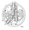
- FIG. 3 shows the nut 19 in its lower end position, in which the operating roller 20 presses on the operating surface 26 of the piston 25b, as a result of which the workpiece is clamped.
- the nut 19 is in its upper end position, in which the clamping jaws 4 (FIG. 1) are in an ineffective position.
- the nut 19 is in its upper end position. Their guides 22 can be clearly seen.
- the clamping head body 1 also has plane surfaces 32, 33 outside for fastening stops or gauges, so that the workpiece can only be inserted into the workpiece support 6 in the desired position.
- the cover 15 that closes the space 14 is designed as a round disk and is guided in a centering 34 of the clamping head body 1. So that the cover 15 to the clamping head body 1 also assumes the correct position in the direction of rotation, a key 35 is finally provided between the two parts 1, 15.
- the design of the outer end face of the cover 15 can be different, it depends on the counterpart, a special partial head being provided in the present case.
- the bias is limited on the drive, not shown, for the threaded spindle 21. After removing this drive, the workpiece remains clamped because the thread of the threaded spindle 21 is designed to be self-locking. Now the rotary movement of the entire system with the clamped workpiece and thus the machining of the crank bearing journal, for example in the case of crankshafts, can begin.
Landscapes
- Engineering & Computer Science (AREA)
- Mechanical Engineering (AREA)
- Jigs For Machine Tools (AREA)
- Grinding Of Cylindrical And Plane Surfaces (AREA)
- Gripping On Spindles (AREA)
Applications Claiming Priority (2)
| Application Number | Priority Date | Filing Date | Title |
|---|---|---|---|
| DE2856037 | 1978-12-23 | ||
| DE19782856037 DE2856037A1 (de) | 1978-12-23 | 1978-12-23 | Vorrichtung zum einspannen von werkstuecken |
Publications (3)
| Publication Number | Publication Date |
|---|---|
| EP0013746A2 true EP0013746A2 (fr) | 1980-08-06 |
| EP0013746A3 EP0013746A3 (en) | 1980-10-15 |
| EP0013746B1 EP0013746B1 (fr) | 1984-10-17 |
Family
ID=6058313
Family Applications (1)
| Application Number | Title | Priority Date | Filing Date |
|---|---|---|---|
| EP79105246A Expired EP0013746B1 (fr) | 1978-12-23 | 1979-12-18 | Dispositif de serrage de pièces à usiner |
Country Status (5)
| Country | Link |
|---|---|
| US (1) | US4475318A (fr) |
| EP (1) | EP0013746B1 (fr) |
| JP (1) | JPS55125906A (fr) |
| DD (1) | DD148196A1 (fr) |
| DE (1) | DE2856037A1 (fr) |
Families Citing this family (4)
| Publication number | Priority date | Publication date | Assignee | Title |
|---|---|---|---|---|
| EP0137202B1 (fr) * | 1983-08-16 | 1988-06-01 | Boart International Limited | Mandrin de serrage pour perforatrice rotative de rocher |
| EP0264476B2 (fr) * | 1986-10-22 | 1996-01-24 | Wilhelm Hegenscheidt Gesellschaft mbH | Machine en particulier pour le brochage par rotation des manetons de vilebrequins coudés plusieurs fois |
| CN102091957A (zh) * | 2009-12-11 | 2011-06-15 | 天津市臣涛精密机械设备有限公司 | 法兰孔专用液压夹具 |
| CN110842598B (zh) * | 2019-11-12 | 2021-11-16 | 天津旗领机电科技有限公司 | 一种用于高速加工摆线齿轮的定位加紧装置 |
Citations (7)
| Publication number | Priority date | Publication date | Assignee | Title |
|---|---|---|---|---|
| CH121387A (de) * | 1926-09-15 | 1927-07-01 | Meier Ernst | Selbstzentrierendes Aufspannfutter. |
| DE605632C (de) * | 1932-11-25 | 1934-11-15 | Wagner & Co Werkzeugmaschinenf | Vorrichtung zum Spannen und Loesen eines unter dem Schnittdruck selbsttaetig nachspannenden, auch zur Aufnahme unrunder Werkstuecke geeignten Mitnehmers fuer Drehbaenke |
| US2067107A (en) * | 1935-02-23 | 1937-01-05 | Harold A Tomkins | Crankshaft chuck |
| US2784977A (en) * | 1955-06-15 | 1957-03-12 | Seneca Falls Machine Co | Multiple jaw chuck with counterbalanced jaws |
| FR1576392A (fr) * | 1968-03-13 | 1969-08-01 | ||
| FR2073190A5 (fr) * | 1969-12-10 | 1971-09-24 | Caterpillar Tractor Co | Mandrin a machoires perfectionne |
| US4083271A (en) * | 1977-03-17 | 1978-04-11 | Usm Corporation | Lathe apparatus |
Family Cites Families (6)
| Publication number | Priority date | Publication date | Assignee | Title |
|---|---|---|---|---|
| US1391441A (en) * | 1917-01-13 | 1921-09-20 | Williamson George | Chuck |
| GB624501A (en) * | 1947-05-12 | 1949-06-09 | Churchill Machine Tool Co Ltd | Improvements relating to work holding means for machines for grinding crankshafts |
| US3585763A (en) * | 1968-07-12 | 1971-06-22 | Litton Industries Inc | Work-driving device for camshaft grinder |
| US3841647A (en) * | 1973-01-10 | 1974-10-15 | Pandjiris Weldment Co | Self-centering chuck mechanism |
| US4023937A (en) * | 1973-08-21 | 1977-05-17 | Landis Lund Limited | Chuck assembly |
| US3881735A (en) * | 1974-03-13 | 1975-05-06 | Warner Swasey Co | Workholder |
-
1978
- 1978-12-23 DE DE19782856037 patent/DE2856037A1/de active Granted
-
1979
- 1979-12-18 EP EP79105246A patent/EP0013746B1/fr not_active Expired
- 1979-12-21 DD DD79218049A patent/DD148196A1/de unknown
- 1979-12-24 JP JP16806479A patent/JPS55125906A/ja active Pending
-
1982
- 1982-02-08 US US06/347,092 patent/US4475318A/en not_active Expired - Fee Related
Patent Citations (7)
| Publication number | Priority date | Publication date | Assignee | Title |
|---|---|---|---|---|
| CH121387A (de) * | 1926-09-15 | 1927-07-01 | Meier Ernst | Selbstzentrierendes Aufspannfutter. |
| DE605632C (de) * | 1932-11-25 | 1934-11-15 | Wagner & Co Werkzeugmaschinenf | Vorrichtung zum Spannen und Loesen eines unter dem Schnittdruck selbsttaetig nachspannenden, auch zur Aufnahme unrunder Werkstuecke geeignten Mitnehmers fuer Drehbaenke |
| US2067107A (en) * | 1935-02-23 | 1937-01-05 | Harold A Tomkins | Crankshaft chuck |
| US2784977A (en) * | 1955-06-15 | 1957-03-12 | Seneca Falls Machine Co | Multiple jaw chuck with counterbalanced jaws |
| FR1576392A (fr) * | 1968-03-13 | 1969-08-01 | ||
| FR2073190A5 (fr) * | 1969-12-10 | 1971-09-24 | Caterpillar Tractor Co | Mandrin a machoires perfectionne |
| US4083271A (en) * | 1977-03-17 | 1978-04-11 | Usm Corporation | Lathe apparatus |
Also Published As
| Publication number | Publication date |
|---|---|
| DD148196A1 (de) | 1981-05-13 |
| EP0013746A3 (en) | 1980-10-15 |
| US4475318A (en) | 1984-10-09 |
| JPS55125906A (en) | 1980-09-29 |
| DE2856037C2 (fr) | 1991-02-07 |
| EP0013746B1 (fr) | 1984-10-17 |
| DE2856037A1 (de) | 1980-07-17 |
Similar Documents
| Publication | Publication Date | Title |
|---|---|---|
| DE4032885A1 (de) | Scheibenbremse fuer fahrzeuge, insbesondere strassenfahrzeuge | |
| DE2102412A1 (de) | Verstelleinrichtung fur Kurbel wellen | |
| EP0425936A2 (fr) | Dispositif pour le repérage, la fixation et la tension rapides de plaques d'impression | |
| DE2530365B2 (de) | Einrichtung zur Durchmesserverstellung eines Zylinders | |
| DE3131107A1 (de) | "vorrichtung zur einstellung der drehachse eines gelenks zur schwenkfaehigen aufhaengung eines fuehrungslenkers eines rades am aufbau eines kraftfahrzeuges" | |
| DE2913641C2 (de) | Zahnstangenlenkung für Kraftfahrzeuge | |
| DE69700231T2 (de) | Selbstzentrierende Lünette mit einfahrbaren Greifarmen | |
| EP0069388B1 (fr) | Support de cylindres d'impression ou similaires, avec dispositif de réglage du repèrage latéral | |
| DE4241565A1 (de) | Lagerung für einen mit einer aufschiebbaren Hülse ausgestatteten Druckzylinder | |
| DE3240416A1 (de) | Schleifwerkzeug fuer industrieroboter oder automatische maschinen | |
| EP0289460B1 (fr) | Dispositif pour tourner des surfaces sphériques sur des tours | |
| EP0013746B1 (fr) | Dispositif de serrage de pièces à usiner | |
| DE3434308A1 (de) | Spannfutter | |
| DE202013003913U1 (de) | Plattenbearbeitungsanlage mit gebremstem Werkstückauflagetisch | |
| DE2557248C3 (de) | Vorrichtung zum Feststellen von Maschinenteilen zueinander | |
| DE2308988C3 (de) | An einer Honvorrichtung angeordnetes Honwerkzeug | |
| DE19535070C2 (de) | Vorrichtung zur drehbaren Lagerung von Kurbelwellen in einer Schleifmaschine | |
| EP0340602B1 (fr) | Commande pour un étau de machine | |
| DE2228654A1 (de) | Vorrichtung zum umsetzen von teilen, insbesondere werkzeugwechselvorrichtung bei werkzeugmaschinen | |
| DE1752467C3 (de) | Vorrichtung zur Verstellung der Exzentrizität des Kurbelzapfens einer von einer alternierend arbeitenden Presse synchron angetriebenen Kurbel | |
| DE3929011A1 (de) | Spanneinrichtung an werkzeugmaschinen | |
| DE4025752C1 (en) | Chuck for machine tool - has short threaded cylindrical block to fit into recess at back of jaw | |
| DE2346477C3 (de) | Anschlagvorrichtung für die Tiefenzustellung des Werkzeugs relativ zum Werkstück bei Zahnradbearbeitungsmaschinen, insbesondere Wälzfräsmaschinen | |
| DE1477040A1 (de) | Werkzeughalter fuer Walzwerkzeuge | |
| DE2447660C3 (de) | Vorrichtung zum Andrücken einer Schablone und eines Linsenrohlings an die Enden einer Werkstückspindel einer Linsenrandschleifmaschine |
Legal Events
| Date | Code | Title | Description |
|---|---|---|---|
| PUAI | Public reference made under article 153(3) epc to a published international application that has entered the european phase |
Free format text: ORIGINAL CODE: 0009012 |
|
| AK | Designated contracting states |
Designated state(s): CH FR GB SE |
|
| PUAL | Search report despatched |
Free format text: ORIGINAL CODE: 0009013 |
|
| AK | Designated contracting states |
Designated state(s): CH FR GB SE |
|
| 17P | Request for examination filed |
Effective date: 19810415 |
|
| RAP1 | Party data changed (applicant data changed or rights of an application transferred) |
Owner name: NAXOS-UNION SCHLEIFMITTEL UND SCHLEIFMASCHINENFABR |
|
| GRAA | (expected) grant |
Free format text: ORIGINAL CODE: 0009210 |
|
| AK | Designated contracting states |
Designated state(s): CH FR GB SE |
|
| PG25 | Lapsed in a contracting state [announced via postgrant information from national office to epo] |
Ref country code: SE Effective date: 19841017 |
|
| PG25 | Lapsed in a contracting state [announced via postgrant information from national office to epo] |
Ref country code: CH Effective date: 19841231 |
|
| ET | Fr: translation filed | ||
| PLBE | No opposition filed within time limit |
Free format text: ORIGINAL CODE: 0009261 |
|
| STAA | Information on the status of an ep patent application or granted ep patent |
Free format text: STATUS: NO OPPOSITION FILED WITHIN TIME LIMIT |
|
| REG | Reference to a national code |
Ref country code: CH Ref legal event code: PL |
|
| 26N | No opposition filed | ||
| PGFP | Annual fee paid to national office [announced via postgrant information from national office to epo] |
Ref country code: GB Payment date: 19911113 Year of fee payment: 13 |
|
| PGFP | Annual fee paid to national office [announced via postgrant information from national office to epo] |
Ref country code: FR Payment date: 19911119 Year of fee payment: 13 |
|
| REG | Reference to a national code |
Ref country code: GB Ref legal event code: 732 |
|
| REG | Reference to a national code |
Ref country code: FR Ref legal event code: TP |
|
| PG25 | Lapsed in a contracting state [announced via postgrant information from national office to epo] |
Ref country code: GB Effective date: 19921218 |
|
| GBPC | Gb: european patent ceased through non-payment of renewal fee |
Effective date: 19921218 |
|
| PG25 | Lapsed in a contracting state [announced via postgrant information from national office to epo] |
Ref country code: FR Effective date: 19930831 |
|
| REG | Reference to a national code |
Ref country code: FR Ref legal event code: ST |