EP0012677B1 - Slope regulating, adjustable hinge - Google Patents
Slope regulating, adjustable hinge Download PDFInfo
- Publication number
- EP0012677B1 EP0012677B1 EP79400980A EP79400980A EP0012677B1 EP 0012677 B1 EP0012677 B1 EP 0012677B1 EP 79400980 A EP79400980 A EP 79400980A EP 79400980 A EP79400980 A EP 79400980A EP 0012677 B1 EP0012677 B1 EP 0012677B1
- Authority
- EP
- European Patent Office
- Prior art keywords
- leaf
- hinge
- gate
- slot
- closed
- Prior art date
- Legal status (The legal status is an assumption and is not a legal conclusion. Google has not performed a legal analysis and makes no representation as to the accuracy of the status listed.)
- Expired
Links
Images

Classifications
-
- E—FIXED CONSTRUCTIONS
- E06—DOORS, WINDOWS, SHUTTERS, OR ROLLER BLINDS IN GENERAL; LADDERS
- E06B—FIXED OR MOVABLE CLOSURES FOR OPENINGS IN BUILDINGS, VEHICLES, FENCES OR LIKE ENCLOSURES IN GENERAL, e.g. DOORS, WINDOWS, BLINDS, GATES
- E06B11/00—Means for allowing passage through fences, barriers or the like, e.g. stiles
- E06B11/02—Gates; Doors
- E06B11/04—Gates; Doors characterised by the kind of suspension
-
- E—FIXED CONSTRUCTIONS
- E05—LOCKS; KEYS; WINDOW OR DOOR FITTINGS; SAFES
- E05D—HINGES OR SUSPENSION DEVICES FOR DOORS, WINDOWS OR WINGS
- E05D7/00—Hinges or pivots of special construction
- E05D7/06—Hinges or pivots of special construction to allow tilting of the members
-
- E—FIXED CONSTRUCTIONS
- E05—LOCKS; KEYS; WINDOW OR DOOR FITTINGS; SAFES
- E05Y—INDEXING SCHEME RELATING TO HINGES OR OTHER SUSPENSION DEVICES FOR DOORS, WINDOWS OR WINGS AND DEVICES FOR MOVING WINGS INTO OPEN OR CLOSED POSITION, CHECKS FOR WINGS AND WING FITTINGS NOT OTHERWISE PROVIDED FOR, CONCERNED WITH THE FUNCTIONING OF THE WING
- E05Y2900/00—Application of doors, windows, wings or fittings thereof
- E05Y2900/40—Application of doors, windows, wings or fittings thereof for gates
Definitions
- the present invention relates to the hinge joints of doors, gates or gates giving access to ramps or terrain of fairly steep slope.
- a solution currently used to combat this difficulty consists in mounting each leaf element in the upper part on a ball joint hinge of vertical axis located in the axis of the post and in the lower part on a lever arm pivoting around a hinge ball with vertical axis located behind the axis of the post, the point of attachment of the leaf on the swivel arm being located vertically in line with the ball of the upper hinge, both located in the median vertical plane of the leaf in "closed" position.
- the opening operation of the leaf by rotation around the fictitious axis passing through the center of the two ball joints makes describe at the point of attachment of the leaf on the pivoting arm a circular movement in an oblique plane determining at the end of rotation a position at both spaced from the pillar and raised above the ground from the point of attachment of the leaf on the pivoting arm placing said leaf in an oblique plane in the "open" position.
- This arrangement considerably reduces the passage width and reflects an unsightly appearance, it does not allow the opening greater than 90 °; moreover, its use is limited to slight slopes and its adjustment is final during assembly.
- a device has also been proposed in FR-A-2,388,970 in which the pivot axis is vertical but where the leaf panel is connected to the hinges not rigidly, but by means of a sliding connection.
- Such a solution requires that the maintenance be carried out with care and frequency that is all the greater as the gate is more exposed to the weather, and is therefore not suitable for many users reluctant to carry out this maintenance.
- Patent DE-C-878.094 describes a device which comprises two legs of unequal length, sealed on the rear face of a pillar and carrying the hinges, these legs not being located one below the other. , but placed so that the upper and lower hinges are in a vertical plane which makes an angle of 45 ° with the plane of the closed gate, this plane deviating from the axis of the passage going towards the rear, L advantage of this geometrical arrangement is that, if, by a shift of the hinges relative to the plane of the leaf, the latter is vertical in the closed position, it is also vertical in the open position, after a pivoting of 90 °.
- the leaf presents only a fairly slight inclination on the vertical when it is between the two open or closed positions, and it is possible to exceed these two positions.
- This arrangement which can also be adapted to the case where the ground is descending and not rising, has the further advantage of not reducing the width of the passage.
- the aforementioned patent does not describe any means of adjustment, it is necessary to rely on the address of the mason who will execute the seals in the pillar, or else in the event of the pillar collapsing, the sealing will have to be redone and the fittings of the portal.
- no industrial prefabrication is possible, given the wide variety of cases that may arise.
- the object of the invention is to avoid these drawbacks, and in particular to solve the problems of opening on slopes of the order of 3 to 25% using a device produced in series and easily adaptable on site.
- Another object of the invention is to provide a device which makes it easy to reset the level in the event of the gate collapsing, as well as a positive or negative adjustment with respect to the average setting, thus allowing catching up in the case where the data on the configuration of the soil prove to be inaccurate.
- the invention aims to provide a device which can be associated with all models of gates and pillars, with hinges to be screwed or sealed, the fixing points of these hinges being placed in the axis of the pillar, allowing thus centering the portal.
- the present invention therefore provides a portal articulation device according to DE-C-878094 giving access to a ramp or sloping ground comprising an upper hinge and a lower hinge each comprising a support plate carried by a fixed support by relative to the ground, a lug secured to the leaf and, between these two parts, pivot connection means which are situated in a vertical plane making an angle of approximately 45 ° with the vertical plane of the closed gate and being outside of the space swept by the leaf when it passes from the open position to the closed position.
- This device is according to the invention characterized in that said pivot connection means which is part of the lower hinge is mounted on the one hand in an oblong groove or buttonhole, executed in said support plate integral with the fixed support, the axis of this groove passing vertically from the pivot means of the other hinge and being situated in said plane at 45 ° and on the other hand on an intermediate connecting piece carried by the leaf, this connecting piece being able to be moved by relative to the leaf and immobilized with respect to the latter by means of a locking means, and in that means are provided for guiding the movement ment of said intermediate piece in a direction which coincides with that of said oblong groove or buttonhole when the gate is closed.
- the lug integral with the leaf and which forms part of the lower hinge has both a groove parallel to the groove of the solid plate of the support when the leaf is closed, the locking screw being housed in this groove, and a slide of common axis with that of the groove and in which the connecting piece is guided in translation, and in that the free end of the connecting piece has a bore in which is inscribed a spherical ring externally placed on the vertical axis of articulation.
- the upper hinge consists of two horizontal legs in the closed portal position fixed, one on the fixed support, the other on the leaf, hinging one on the other about a vertical axis integral with the tab fixed on the fixed support, and on said axis, is mounted an externally spherical ring, which is housed in a cylindrical bore of the tab fixed on the leaf.
- the device allowing the leaf 1 to pivot on the pillar 2 consists of an upper hinge 3 and a lower hinge 4 respectively comprising a support plate 3a and 4a, the fixing of which on the pillar s 'performs in line with it.
- a reinforcement 5 consisting of a steel profile is placed inside the pillar, in which reinforcement are implanted the screws for fixing the hinges 3 and 4.
- the upper hinge 3 has a horizontal tab 3b at the end of which is installed the vertical upper articulation axis 6, which carries an externally spherical ring 7 free to rotate on the axis 6. This axis of upper articulation 6 is contained in the frontal median plane of the leaf.
- the lower hinge 4 comprises a horizontal plate 4b offset towards the rear of the pillar 2; on this plate 4b is executed an oblong groove or buttonhole 8 disposed at 45 ° relative to the frontal plane of the portal, the rear end of which groove approaches the pillar.
- this groove is installed, after adjustment in position, the vertical lower articulation axis 9 carrying an externally spherical ring 10, free to rotate on the axis 9.
- the leaf 1 comprises a horizontal support plate 11 placed at the part lower 1a of the vertical pillar side pillar. On this support plate is executed an oblong or buttonhole groove 12 disposed at 45 ° relative to the frontal plane of the leaf, the rear end of said groove approaching the pillar by similarity with the groove of the plate 4b secured to the lower hinge 4.
- a locking screw 13 of a connecting piece 14 interposed between the plates 11 and 4b and playing the role of pivot arm of the leaf around the lower axis of rotation 9.
- This piece of connection positioned in the axis of the groove 12 of the support plate 11 by means of a slide 15 inclined at 45 ° comprises at its end a bore 16 adjusting rotating on the spherical ring 10.
- a lug 17 At the upper part 1 b the vertical upright, pillar side of the leaf, is fixed a lug 17, the end of which has a bore 18 situated in the frontal median plane of the leaf 1 of the portal and intended to adjust rotating on the ring 7 of the upper hinge 3.
- an adjustment by displacement along arrow F3 of the lower vertical axis of rotation 9 followed by an adjustment of verticality correction by displacement of the screw 13 according to arrow F4 allows the lower end of the leaf to reach a lower level in the open position in the case of terrain of low ascent. In all cases, the leaf is in a vertical plane both in the full open position and in the closed position.
- the device which is the subject of the invention can be used on all gates, wickets or doors and pillars and whatever the type of hinges used, to be screwed or sealed.
Abstract
Description
La présente invention concerne les gonds d'articulation de portes, portillons ou portails donnant accès à des rampes ou des terrains de pente assez accentuée.The present invention relates to the hinge joints of doors, gates or gates giving access to ramps or terrain of fairly steep slope.
La difficulté la plus fréquemment rencontrée pour assurer une ouverture complète du ou des vantaux réside dans l'interférence de la partie inférieure de celui-ci ou de ceux-ci avec le sol au cours de la manoeuvre d'ouverture, lorsque le sol est montant dans la direction où le vantail doit se rabattre, direction qui sera dite "arrière" dans la suite du texte. L'augmentation de la garde au sol en position "fermée" ne peut être envisagée par l'aspect inesthétique que cela engendre et cela plus particulièrement en ce qui concerne les éléments de portails permettant le passage d'un véhicule en raison de l'important dimensionnelle de leur débattement. Une solution actuellement utilisée pour combattre cette difficulté consiste à monter chaque élément de vantail en partie haute sur un gond à rotule d'axe vertical situé dans l'axe du poteau et en partie basse sur un bras de levier pivotant autour d'un gond à rotule d'axe vertical situé en arrière de l'axe du poteau, le point d'attache du vantail sur le bras pivotant étant sité à l'aplomb vertical de la rotule du gond supérieur tous deux situés dans le plan vertical médian du vantail en position "fermée". La manoeuvre d'ouverture du vantail par rotation autour de l'axe fictif passant par le centre des deux rotules fait décrire au point d'attache du vantail sur le bras pivotant un mouvement circulaire dans un plan oblique déterminant en fin de rotation une position à la fois ecartée du pilier et surélevée par rapport au sol du point d'attache du vantail sur le bras pivotant plaçant ledit vantail dans un plan oblique en position "ouvert". Cette disposition réduit considérablement la largeur de passage et reflète un aspect inesthétique, elle ne permet pas l'ouverture supérieure à 90°; de plus, son utilisation est limitée à de faibles pentes et son réglage est définitif au montage.The most frequently encountered difficulty in ensuring complete opening of the leaf (s) lies in the interference of the lower part thereof or of these with the ground during the opening maneuver, when the ground is rising. in the direction where the leaf must fold, direction which will be called "back" in the rest of the text. The increase in ground clearance in the "closed" position cannot be envisaged by the unsightly aspect that this generates and this more particularly with regard to the elements of gates allowing the passage of a vehicle due to the important dimensional of their travel. A solution currently used to combat this difficulty consists in mounting each leaf element in the upper part on a ball joint hinge of vertical axis located in the axis of the post and in the lower part on a lever arm pivoting around a hinge ball with vertical axis located behind the axis of the post, the point of attachment of the leaf on the swivel arm being located vertically in line with the ball of the upper hinge, both located in the median vertical plane of the leaf in "closed" position. The opening operation of the leaf by rotation around the fictitious axis passing through the center of the two ball joints makes describe at the point of attachment of the leaf on the pivoting arm a circular movement in an oblique plane determining at the end of rotation a position at both spaced from the pillar and raised above the ground from the point of attachment of the leaf on the pivoting arm placing said leaf in an oblique plane in the "open" position. This arrangement considerably reduces the passage width and reflects an unsightly appearance, it does not allow the opening greater than 90 °; moreover, its use is limited to slight slopes and its adjustment is final during assembly.
On a également proposé dans FR-A-2.388.970 un dispositif dans lequel l'axe de pivotement est vertical mais où le panneau du vantail est relié aux gonds non pas rigidement, mais à l'aide d'une liaison coulissante. Une telle solution exige que l'entretien soit réalisé avec un soin et une fréquence d'autant plus grands que le portail est plus exposé aux intemperies, et ne convient donc pas pour beaucoup d'utilisateurs peu enclins à realiser cet entretien.A device has also been proposed in FR-A-2,388,970 in which the pivot axis is vertical but where the leaf panel is connected to the hinges not rigidly, but by means of a sliding connection. Such a solution requires that the maintenance be carried out with care and frequency that is all the greater as the gate is more exposed to the weather, and is therefore not suitable for many users reluctant to carry out this maintenance.
Le brevet DE-C-878.094 décrit un dispositif qui comporte deux pattes d'inégale longueur, scellées sur la face arriere d'un pilier et portant les gonds, ces pattes n'étant pas situées l'une au-dessous de l'autre, mais placées de telle sorte que les gonds supérieur et inférieur sont dans un plan vertical qui fait un angle de 45° avec le plan du portail fermé, ce plan s'écartant de l'axe du passage en allant vers l'arrière, L'avantage de cette disposition géométrique est que, si, par un décalage des gonds par rapport au plan du vantail, celui-ci est vertical dans la position fermée, il est également vertical dans la position ouverte, après un pivotement de 90°. Pendant la manoeuvre, le vantail ne présente qu'une inclinaison assez faible sur la verticale quand il est entre les deux positions ouverte ou fermée, et il est possible de dépasser ces deux positions. Cette disposition, qui peut également être adaptée au cas où le terrain est descendant et non montant, présente en outre l'avantage de ne pas réduire la largeur du passage. Toutefois, le brevet précité ne décrit aucun moyen de réglage, il faut se fier à l'adresse du maçon qui exécutera les scellements dans le pilier, ou bien en cas d'affaissement du pilier, il faudra refaire le scellement et changer les ferrures du portail. En outre, aucune préfabrication industrielle n'est possible, étant donné la grande variété de cas qui peuvent se présenter.Patent DE-C-878.094 describes a device which comprises two legs of unequal length, sealed on the rear face of a pillar and carrying the hinges, these legs not being located one below the other. , but placed so that the upper and lower hinges are in a vertical plane which makes an angle of 45 ° with the plane of the closed gate, this plane deviating from the axis of the passage going towards the rear, L advantage of this geometrical arrangement is that, if, by a shift of the hinges relative to the plane of the leaf, the latter is vertical in the closed position, it is also vertical in the open position, after a pivoting of 90 °. During the maneuver, the leaf presents only a fairly slight inclination on the vertical when it is between the two open or closed positions, and it is possible to exceed these two positions. This arrangement, which can also be adapted to the case where the ground is descending and not rising, has the further advantage of not reducing the width of the passage. However, the aforementioned patent does not describe any means of adjustment, it is necessary to rely on the address of the mason who will execute the seals in the pillar, or else in the event of the pillar collapsing, the sealing will have to be redone and the fittings of the portal. Furthermore, no industrial prefabrication is possible, given the wide variety of cases that may arise.
L'invention a pour but d'éviter ces inconvénients, et en particulier de résoudre les problèmes d'ouverture sur des pentes de l'ordre de 3 à 25% à l'aide d'un appareillage fabriqué en série et facilement adaptable sur place. L'invention a également pour but un dispositif qui rende aisée une remise de niveau en cas d'affaissement du portail, ainsi qu'un réglage positif ou négatif par rapport au réglage moyen permettant ainsi un rattrapage dans le cas où les données sur la configuration du sol se révèlent inexactes. Enfin, l'invention a pour but de fournir un dispositif qui puisse être associé à tous modèles de portails et de piliers, avec gonds à visser ou à sceller, les points de fixation de ces gonds étant placés dans l'axe du pilier, permettant ainsi le centrage du portail.The object of the invention is to avoid these drawbacks, and in particular to solve the problems of opening on slopes of the order of 3 to 25% using a device produced in series and easily adaptable on site. . Another object of the invention is to provide a device which makes it easy to reset the level in the event of the gate collapsing, as well as a positive or negative adjustment with respect to the average setting, thus allowing catching up in the case where the data on the configuration of the soil prove to be inaccurate. Finally, the invention aims to provide a device which can be associated with all models of gates and pillars, with hinges to be screwed or sealed, the fixing points of these hinges being placed in the axis of the pillar, allowing thus centering the portal.
La présente invention fournit donc un dispositif d'articulation de portail selon le DE-C-878094 donnant accès à une rampe ou un terrain en pente comportant un gond supérieur et un gond inférieur comprenant chacun une platine d'appui portée par un support fixe par rapport au sol, une patte solidaire du vantail et, entre ces deux pièces, des moyens de liaison à pivot qui sont situés dans un plan vertical faisant un angle de 45° environ avec le plan vertical du portail fermé et se trouvant à l'extérieur de l'espace balayé par le vantail quand il passe de la position d'ouverture à la position de fermeture. Ce dispositif est selon l'invention caractérisé en ce que ledit moyen de liaison à pivot qui fait partie du gond inférieur est monté d'une part dans une rainure ou boutonnière oblongue, exécutée dans ladite platine d'appui solidaire du support fixe, l'axe de cette rainure passant à la verticale du moyen à pivot de l'autre gond et étant situé dans ledit plan à 45° et d'autre part sur une pièce de liaison intermédiaire portée par le vantail, cette pièce de liaison pouvant être déplacée par rapport au vantail et immobilisée par rapport à ce dernier grâce à un moyen de blocage, et en ce que des moyens sont prévus pour guider le déplacement de ladite pièce intermédiaire dans une direction qui coïncide avec celle de ladite rainure ou boutonnière oblongue quand le portail est fermé.The present invention therefore provides a portal articulation device according to DE-C-878094 giving access to a ramp or sloping ground comprising an upper hinge and a lower hinge each comprising a support plate carried by a fixed support by relative to the ground, a lug secured to the leaf and, between these two parts, pivot connection means which are situated in a vertical plane making an angle of approximately 45 ° with the vertical plane of the closed gate and being outside of the space swept by the leaf when it passes from the open position to the closed position. This device is according to the invention characterized in that said pivot connection means which is part of the lower hinge is mounted on the one hand in an oblong groove or buttonhole, executed in said support plate integral with the fixed support, the axis of this groove passing vertically from the pivot means of the other hinge and being situated in said plane at 45 ° and on the other hand on an intermediate connecting piece carried by the leaf, this connecting piece being able to be moved by relative to the leaf and immobilized with respect to the latter by means of a locking means, and in that means are provided for guiding the movement ment of said intermediate piece in a direction which coincides with that of said oblong groove or buttonhole when the gate is closed.
De préférence, la patte solidaire du vantail et qui fait partie du gond inférieur comporte à la fois une rainure parallèle à la rainure de la plaque solidiare du support quand le vantail est fermé, la vis de blocage étant logée dans cette rainure, et une glissière d'axe commun avec celui de la rainure et dans laquelle la pièce de liaison est guidée en translation, et en ce que l'extrémité libre de la pièce de liaison comporte un alésage dans lequel s'inscrit une bague sphérique extérieurement placée sur l'axe vertical d'articulation.Preferably, the lug integral with the leaf and which forms part of the lower hinge has both a groove parallel to the groove of the solid plate of the support when the leaf is closed, the locking screw being housed in this groove, and a slide of common axis with that of the groove and in which the connecting piece is guided in translation, and in that the free end of the connecting piece has a bore in which is inscribed a spherical ring externally placed on the vertical axis of articulation.
Avantageusement, le gond supérieur est constitué de deux pattes horizontales en position portail fermé fixées, l'une sur le support fixe, l'autre sur le vantail, s'articulant l'une sur l'autre autour d'une axe vertical solidaire de la patte fixée sur le support fixe, et sur ledit axe, est montée une bague sphérique extérieurement, laquelle se loge dansun alésage cylindrique de la patte fixée sur le vantail.Advantageously, the upper hinge consists of two horizontal legs in the closed portal position fixed, one on the fixed support, the other on the leaf, hinging one on the other about a vertical axis integral with the tab fixed on the fixed support, and on said axis, is mounted an externally spherical ring, which is housed in a cylindrical bore of the tab fixed on the leaf.
La présente invention sera exposée plus en détail à l'aide d'un exemple, illustré par les dessins annexées parmi lesquels:
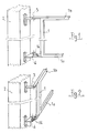
- Fig. 1 est une vue en perspective cavalière d'un vantail selon l'invention en position fermée,
- Fig. 2 est une vue en perspective cavalière de ce vantail en position ouverte,
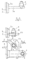
- Fig. 3 est une vue en élévation d'un pilier équipé des gonds supérieur et inférieur,
- Fig. 4 est une vue de dessus du pilier correspondant à la figure 3,
- Fig. 5 est une vue en élévation du montant vertical du vantail comportant les éléments d'articulation sur les gonds du pilier, et
- Fig. 6 est une vue de dessus correspondant à la figure 5.
- Fig. 1 is a perspective view of a leaf according to the invention in the closed position,
- Fig. 2 is a perspective view of this leaf in the open position,
- Fig. 3 is an elevation view of a pillar equipped with the upper and lower hinges,
- Fig. 4 is a top view of the pillar corresponding to FIG. 3,
- Fig. 5 is an elevational view of the vertical amount of the leaf comprising the articulation elements on the hinges of the pillar, and
- Fig. 6 is a top view corresponding to FIG. 5.
Tel qu'il est représenté le dispositif permettant le pivotement du vantail 1 sur le pilier 2 se compose d'un gond supérieur 3 et d'un gond inférieur 4 comportant respectivement une platine d'appui 3a et 4a dont la fixation sur le pilier s'effectue dans l'axe de celui-ci. Dans la réalisation représentée dans les dessins annexés et relatifs à un pilier en matière plastique, un renfort 5 constitué d'un profil d'acier est placé à l'intérieur du pilier, dans lequel renfort s'implantent les vis de fixation des gonds 3 et 4. Le gond supérieur 3 comporte une patte horizontale 3b à l'extrémité de laquelle est implanté l'axe vertical d'articulation supérieur 6, lequel porte une bague sphérique extérieurement 7 libre en rotation sur l'axe 6. Cet axe d'articulation supérieur 6 est contenu dans le plan médian frontal du vantail. Le gond inférieur 4 comporte une plaque horizontale 4b déportée vers l'arrière du pilier 2; sur cette plaque 4b est exécutée une rainure oblongue ou boutonnière 8 disposée à 45° par rapport au plan frontal du portail, l'extrémité arrière de laquelle rainure se rapproche du pilier. Dans cette rainure est implanté, après réglage en position, l'axe vertical d'articulation inférieure 9 portant une bague sphérique extérieurement 10, libre en rotation sur l'axe 9. Le vantail 1 comporte une plaque-support horizontale 11 placée à la partie inférieur 1a du montant vertical côté pilier. Sur cette plaque support est exécutée une rainure oblongue ou boutonnière 12 disposée à 45° par rapport au plan frontal du vantail, l'extrémité arrière de ladite rainure se rapprochant du pilier par similitude avec la rainure de la plaque 4b solidaire du gond inférieur 4. Dans cette rainure 12 se loge une vis de blocage 13 d'une pièce de liaison 14 s'interposant entre les plaques 11 et 4b et jouant le rôle de bras de pivotement du vantail autour de l'axe de rotation inférieur 9. Cette pièce de liaison positionnée dans l'axe de la rainure 12 de la plaque-support 11 au moyen d'une glissière 15 inclinée à 45° comporte en son extrémité un alésage 16 s'ajustant tournant sur la bague sphérique 10. A la partie supérieure 1 b du montant vertical, côté pilier du vantail, est fixée une patte 17 dont l'extrémité comporte un alésage 18 situé dans le plan médian frontal du vantail 1 du portail et destiné à s'ajuster tournant sur la bague 7 du gond supérieur 3. Lorsque le vantail 1 se trouve en position fermée, les axes d'articulation supérieur 6 et inférieur 9 et l'axe des rainures ou boutonnières 8 et 12 et de la pièce de liaison 14 sont contenus dans un plan vertical commun orienté à 45° par rapport au plan frontal du vantail 1 du portail.As shown, the device allowing the
Pour obtenir l'ouverture complète à 90° du vantail 1 dans risque de talonnage avec la remontée du terrain, il suffit de positionner correctement l'axe vertical de rotation inférieur 9, celui-ci devant se situer plus en arrière du pilier 2, selon que le sol est plus ascendant. Ce réglage par déplacement selon la flèche F1 a pour effet d'abaisser l'extrémité du vantail 1 en position fermée et de placer celui-ci dans un plan oblique par rapport au plan frontal du vantail. La correction de verticalité s'effectue par le réglage en position de la vis 13 dans le rainure 12 par. déplacement selon la flèche F2. La combinaison de ces deux réglages tend à remonter l'extrémité inférieure du vantail 1 en position ouverte. De même, un réglage par déplacement selon la flèche F3 de l'axe vertical de rotation inférieur 9 suivi d'un réglage de correction de verticalité par déplacement de la vis 13 selon la flèche F4 permet à l'extrémité inférieure du vantail d'atteindre un niveau moins élevé en position d'ouverture dans le cas de terrain de faible remontée. Dans tous les cas, le vantail se situe dans un plan vertical tant en position complète d'ouverture qu'en position de fermeture.To obtain full opening of the
L'invention ne se limite aucunement au mode de réalisation spécialement indiqué, mais elle admet toutes variantes possibles à condition que celles-ci ne soient pas en contradiction avec l'objet de chacune des revendications annexées à la présente description.The invention is in no way limited to the specially indicated embodiment, but it admits all possible variants provided that these are not in contradiction with the subject of each of the claims annexed to this description.
Le dispositif objet de l'invention peut être utilisé sur tous les portails, portillons ou portes et piliers et quel que soit le type de gonds utilisés, à visser ou à sceller.The device which is the subject of the invention can be used on all gates, wickets or doors and pillars and whatever the type of hinges used, to be screwed or sealed.
Claims (3)
Priority Applications (1)
| Application Number | Priority Date | Filing Date | Title |
|---|---|---|---|
| AT79400980T ATE12043T1 (en) | 1978-12-07 | 1979-12-06 | SLOPE ADJUSTABLE DOOR HINGE. |
Applications Claiming Priority (2)
| Application Number | Priority Date | Filing Date | Title |
|---|---|---|---|
| FR7835713 | 1978-12-07 | ||
| FR7835713A FR2443551A1 (en) | 1978-12-07 | 1978-12-07 | ADJUSTABLE SLOPE REGULATOR |
Publications (2)
| Publication Number | Publication Date |
|---|---|
| EP0012677A1 EP0012677A1 (en) | 1980-06-25 |
| EP0012677B1 true EP0012677B1 (en) | 1985-03-06 |
Family
ID=9216304
Family Applications (1)
| Application Number | Title | Priority Date | Filing Date |
|---|---|---|---|
| EP79400980A Expired EP0012677B1 (en) | 1978-12-07 | 1979-12-06 | Slope regulating, adjustable hinge |
Country Status (4)
| Country | Link |
|---|---|
| EP (1) | EP0012677B1 (en) |
| AT (1) | ATE12043T1 (en) |
| DE (1) | DE2967402D1 (en) |
| FR (1) | FR2443551A1 (en) |
Families Citing this family (6)
| Publication number | Priority date | Publication date | Assignee | Title |
|---|---|---|---|---|
| FR2545528B1 (en) * | 1983-05-03 | 1985-10-11 | Viallard Rene | PIVOTING FENCE DOOR EVOLVING ON SLOPE |
| FR2600370A1 (en) * | 1986-06-19 | 1987-12-24 | Zimmermann Bruno | Offset-pivoting gate device |
| DE59002896D1 (en) * | 1989-07-19 | 1993-11-04 | Alberts Gmbh & Co Kg G | LIFTING FITTING FOR A GATE. |
| ES2161102B1 (en) * | 1998-03-05 | 2002-06-16 | Cruzado Manuel Lomena | FOLDING DOOR FOR Fence. |
| FR2922574B1 (en) * | 2007-10-23 | 2016-12-30 | Stor'm Sarl | JOINT DEVICE FOR PORTAL OPENING ON GROUND FLOOR |
| GB201111529D0 (en) * | 2011-07-06 | 2011-08-17 | Price Paul S | Hinge assembly, door assembly and related methods |
Citations (1)
| Publication number | Priority date | Publication date | Assignee | Title |
|---|---|---|---|---|
| DE878094C (en) * | 1951-07-21 | 1953-06-01 | Linker Kommanditgesellschaft | Tilting gate or door |
Family Cites Families (1)
| Publication number | Priority date | Publication date | Assignee | Title |
|---|---|---|---|---|
| FR2388970A1 (en) * | 1977-04-25 | 1978-11-24 | Masson Emile | Gate for sloping drive or path - has ball joint hinge pins with lower pin sliding in gate bottom rail when opened upwards on support castor |
-
1978
- 1978-12-07 FR FR7835713A patent/FR2443551A1/en active Granted
-
1979
- 1979-12-06 DE DE7979400980T patent/DE2967402D1/en not_active Expired
- 1979-12-06 AT AT79400980T patent/ATE12043T1/en not_active IP Right Cessation
- 1979-12-06 EP EP79400980A patent/EP0012677B1/en not_active Expired
Patent Citations (1)
| Publication number | Priority date | Publication date | Assignee | Title |
|---|---|---|---|---|
| DE878094C (en) * | 1951-07-21 | 1953-06-01 | Linker Kommanditgesellschaft | Tilting gate or door |
Also Published As
| Publication number | Publication date |
|---|---|
| FR2443551A1 (en) | 1980-07-04 |
| FR2443551B1 (en) | 1983-05-13 |
| ATE12043T1 (en) | 1985-03-15 |
| EP0012677A1 (en) | 1980-06-25 |
| DE2967402D1 (en) | 1985-04-11 |
Similar Documents
| Publication | Publication Date | Title |
|---|---|---|
| EP0493225A1 (en) | Pivoting side door for motor vehicle | |
| EP1722052A1 (en) | Lock for an entry door in a section door, in particular for garages | |
| EP2248988A1 (en) | Wing suspension of a gate for sloping terrain | |
| EP0012677B1 (en) | Slope regulating, adjustable hinge | |
| EP0467728B1 (en) | Fitting device for a casement of a pivot-hung window with improved closure | |
| FR2587942A1 (en) | SLIDING SUNROOF FOR MOTOR VEHICLES | |
| EP0924377B1 (en) | Hinge fitting for door, window or similar | |
| EP0330794B1 (en) | Turnable and tiltable window with opening possibilities | |
| FR2775639A1 (en) | Hinge mechanism for fold away table used in motor vehicle | |
| EP1788176A1 (en) | Door hinge with integrated doorstop | |
| FR2584132A1 (en) | Step bearing with automatic slope compensation for external doors and gates opening on a slope | |
| FR2751370A1 (en) | Finger trapping protection hinge for door | |
| FR2877682A1 (en) | Adjusting device for e.g. door, has movable lift-off hinge with end comprising notched convex cylindrical side clamped against notched concave cylindrical sides of lateral edge of door leaf | |
| EP0237381B1 (en) | Hinge device of a swinging shutter with two open positions | |
| FR2696499A1 (en) | Device for closing an opening made in the wall of a room protected against fire. | |
| EP0013228B1 (en) | Device for holding a window in an opened position | |
| FR2627728A1 (en) | MECHANISM FOR OPENING AND CLOSING BUCKET DOOR CONTROL, INCLUDING AGRICULTURAL TRAILER | |
| EP1093971A1 (en) | Load-carrier for a vehicle and vehicle with such a carrier | |
| EP0498745B1 (en) | Fuel tank inlet cover for an automotive vehicle | |
| FR2471470A1 (en) | Ball jointed hinge hooks for side-hung gate - allow pivoting about inclined axis which is offset laterally to accommodate unequal angle straps of gate | |
| FR2692849A1 (en) | Opening roof panel for vehicles - is shaped as segment of disk, with vertical axis, around which panel rotates to open | |
| FR2685380A1 (en) | Iron fitting for a gate designed to be installed on sloping ground | |
| FR2600370A1 (en) | Offset-pivoting gate device | |
| FR2731461A1 (en) | Automatic staggering mechanism for closing and opening double shutters | |
| FR3120244A1 (en) | Swing shutter control mechanism |
Legal Events
| Date | Code | Title | Description |
|---|---|---|---|
| PUAI | Public reference made under article 153(3) epc to a published international application that has entered the european phase |
Free format text: ORIGINAL CODE: 0009012 |
|
| AK | Designated contracting states |
Designated state(s): AT BE CH DE GB IT LU NL SE |
|
| ITCL | It: translation for ep claims filed |
Representative=s name: STUDIO TORTA SOCIETA' SEMPLICE |
|
| TCAT | At: translation of patent claims filed | ||
| DET | De: translation of patent claims | ||
| 17P | Request for examination filed |
Effective date: 19801217 |
|
| GRAA | (expected) grant |
Free format text: ORIGINAL CODE: 0009210 |
|
| AK | Designated contracting states |
Designated state(s): AT BE CH DE GB IT LU NL SE |
|
| PG25 | Lapsed in a contracting state [announced via postgrant information from national office to epo] |
Ref country code: SE Effective date: 19850306 Ref country code: NL Effective date: 19850306 Ref country code: IT Free format text: LAPSE BECAUSE OF FAILURE TO SUBMIT A TRANSLATION OF THE DESCRIPTION OR TO PAY THE FEE WITHIN THE PRESCRIBED TIME-LIMIT;WARNING: LAPSES OF ITALIAN PATENTS WITH EFFECTIVE DATE BEFORE 2007 MAY HAVE OCCURRED AT ANY TIME BEFORE 2007. THE CORRECT EFFECTIVE DATE MAY BE DIFFERENT FROM THE ONE RECORDED. Effective date: 19850306 Ref country code: AT Effective date: 19850306 |
|
| REF | Corresponds to: |
Ref document number: 12043 Country of ref document: AT Date of ref document: 19850315 Kind code of ref document: T |
|
| REF | Corresponds to: |
Ref document number: 2967402 Country of ref document: DE Date of ref document: 19850411 |
|
| NLV1 | Nl: lapsed or annulled due to failure to fulfill the requirements of art. 29p and 29m of the patents act | ||
| PG25 | Lapsed in a contracting state [announced via postgrant information from national office to epo] |
Ref country code: LU Free format text: LAPSE BECAUSE OF NON-PAYMENT OF DUE FEES Effective date: 19851231 Ref country code: CH Effective date: 19851231 Ref country code: BE Effective date: 19851231 |
|
| PLBE | No opposition filed within time limit |
Free format text: ORIGINAL CODE: 0009261 |
|
| STAA | Information on the status of an ep patent application or granted ep patent |
Free format text: STATUS: NO OPPOSITION FILED WITHIN TIME LIMIT |
|
| 26N | No opposition filed | ||
| BERE | Be: lapsed |
Owner name: PLASTICLOTURE Effective date: 19851231 |
|
| GBPC | Gb: european patent ceased through non-payment of renewal fee | ||
| REG | Reference to a national code |
Ref country code: CH Ref legal event code: PL |
|
| PG25 | Lapsed in a contracting state [announced via postgrant information from national office to epo] |
Ref country code: DE Effective date: 19860902 |
|
| PG25 | Lapsed in a contracting state [announced via postgrant information from national office to epo] |
Ref country code: GB Effective date: 19881118 |