EP0011894B1 - Méthode et appareillage pour l'installation d'un élément tubulaire au fond de l'eau - Google Patents
Méthode et appareillage pour l'installation d'un élément tubulaire au fond de l'eau Download PDFInfo
- Publication number
- EP0011894B1 EP0011894B1 EP79200678A EP79200678A EP0011894B1 EP 0011894 B1 EP0011894 B1 EP 0011894B1 EP 79200678 A EP79200678 A EP 79200678A EP 79200678 A EP79200678 A EP 79200678A EP 0011894 B1 EP0011894 B1 EP 0011894B1
- Authority
- EP
- European Patent Office
- Prior art keywords
- tubular element
- pumping unit
- water
- cable
- pump
- Prior art date
- Legal status (The legal status is an assumption and is not a legal conclusion. Google has not performed a legal analysis and makes no representation as to the accuracy of the status listed.)
- Expired
Links
- XLYOFNOQVPJJNP-UHFFFAOYSA-N water Substances O XLYOFNOQVPJJNP-UHFFFAOYSA-N 0.000 title claims description 40
- 238000000034 method Methods 0.000 title claims description 15
- 238000005086 pumping Methods 0.000 claims description 49
- 230000008878 coupling Effects 0.000 claims description 6
- 238000010168 coupling process Methods 0.000 claims description 6
- 238000005859 coupling reaction Methods 0.000 claims description 6
- 238000004873 anchoring Methods 0.000 description 9
- 238000007667 floating Methods 0.000 description 9
- 238000009434 installation Methods 0.000 description 7
- 238000004891 communication Methods 0.000 description 6
- 229910000831 Steel Inorganic materials 0.000 description 3
- 238000005553 drilling Methods 0.000 description 3
- 230000035515 penetration Effects 0.000 description 3
- 239000010959 steel Substances 0.000 description 3
- 239000004020 conductor Substances 0.000 description 2
- 238000010276 construction Methods 0.000 description 1
- 238000012937 correction Methods 0.000 description 1
- 238000006073 displacement reaction Methods 0.000 description 1
- 239000012530 fluid Substances 0.000 description 1
- 210000003128 head Anatomy 0.000 description 1
- 239000007788 liquid Substances 0.000 description 1
- 238000004519 manufacturing process Methods 0.000 description 1
- 239000000463 material Substances 0.000 description 1
- 238000007789 sealing Methods 0.000 description 1
Images

Classifications
-
- B—PERFORMING OPERATIONS; TRANSPORTING
- B63—SHIPS OR OTHER WATERBORNE VESSELS; RELATED EQUIPMENT
- B63B—SHIPS OR OTHER WATERBORNE VESSELS; EQUIPMENT FOR SHIPPING
- B63B21/00—Tying-up; Shifting, towing, or pushing equipment; Anchoring
- B63B21/24—Anchors
- B63B21/26—Anchors securing to bed
- B63B21/27—Anchors securing to bed by suction
-
- E—FIXED CONSTRUCTIONS
- E02—HYDRAULIC ENGINEERING; FOUNDATIONS; SOIL SHIFTING
- E02D—FOUNDATIONS; EXCAVATIONS; EMBANKMENTS; UNDERGROUND OR UNDERWATER STRUCTURES
- E02D2250/00—Production methods
- E02D2250/0053—Production methods using suction or vacuum techniques
Definitions
- the invention relates to a method of installing a tubular element in the bottom of a body of water and to an apparatus for carrying out this method.
- Object of the invention is to remedy this drawback.
- the method according to the invention is characterized in that the pumping unit is removably mounted on the tubular element either before or after the lowering of the tubular element to the water bottom, and that, after stopping the operation of the pumping unit, the pumping unit is disconnected from the tubular element, raised to the water surface and recovered.
- an apparatus for carrying out the method of the invention.
- the apparatus comprises a tubular element which is adapted to be closed at the upper end and which is open at the lower end.
- the apparatus further comprises a thin cutting edge at the lower end of the tubular element, and a pumping unit for reducing the pressure within the tubular element.
- the pumping unit is removably connected to the tubular element by a remotely controlled releasable coupling.
- the pumping unit is adapted to be remotely controlled, and is provided with hoisting means extendible from the water surface to the water bottom for raising the pumping unit to the water surface.
- the apparatus according to the invention has the advantage over the apparatus of the above cited USA patent specification No. 3,496,900, that since the pump is mounted on the tubular element during the installation period, the long fragile hose required to form a fluid communication between the tubular element and the pump of the known apparatus, is not required.
- the pump when mounted on the tubular element allows the generation of a force to drive the tubular element into the water bottom that is considerably larger than the force that can be generated in the known apparatus, wherein the pump is installed on a work-boat. Therefore, the apparatus according to the invention does not require the presence of the ballast weight of the prior art apparatus, which is a further advantage since such ballast weight renders the tubular element top-heavy and prone to being placed in a slant position in the water bottom, or even to be overturned during the placing procedure.
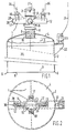
- a tubular element 2 for example made of steel, is closed at its upper end 3 by means of a cap 4.
- the lower end 5 of the tubular element 2 is open and is provided with a cutting edge 6 which enables the tubular element 2 to penetrate into the bottom 7 of a body of water 8.
- the cap 4 is provided with a piece of pipe 9 and a pumping unit 10 is connected by means of a releasable coupling 11 to the upper end of the piece of pipe 9.
- the lower end of the piece of pipe 9 is provided with a sieve cap 19 for preventing ground material from reaching the pumping unit.
- the releasable coupling 11 can be a conventional remotely controlled releasable coupling (for example mechanically, hydraulically, pneumatically or electrically controlled or controlled by a combination thereof).
- the pumping unit 10 is provided with two radial hollow arms 12, each arm 12 carrying a sheave 13 respectively 14, and each sheave being rotatable around a corresponding axis 15 respectively 16 and cooperating with a hoisting cable or -chain 26.
- a pump (not shown) is arranged and within the right hand arm 12 an electric motor (not shown) is arranged for driving the pump.
- valves 17 and 18 are so arranged that they can open or close a communication between the interior 20 and the exterior of the tubular element 2.
- These valves 17 and 18 are conventional remotely controlled valves (for example hydraulically, pneumatically or electrically controlled).
- the outer surface of the tubular element 2 is provided with a radial member 22 which carries a universal joint 23 for connecting an anchor line 24 to the tubular element 2.
- An umbilical cable 27 is connected to the pumping unit 10 in the manner shown in the drawings.
- the discharge of the pump is indicated by reference numeral 30 and is provided with a suitable one- way valve 28.
- the installation of the tubular element 2 is carried out as follows.
- the apparatus 1 is lowered by means of a hoist 29 which is provided with a hoisting cable or -chain 26.
- a hoisting cable or -chain 26 is passed along the sheaves 13 and 14 and by gradually paying out the hoisting cable 26, the apparatus 1 is lowered to the bottom 7 (see Figure 3).
- the air release valves 17 and 18 are opened so that air can escape from the interior 20 of the tubular element 2 during the lowering operation.
- the hoisting line 26 is slackened somewhat so as to allow the cutting edge 6 to penetrate into the bottom 7 over a small distance under the weight of the tubular element 2 and of the pumping unit 10, in order to form a seal around the base of the tubular element 1.
- the air release valves 17 and 18 are closed and the pumping unit 10 is started from the vessel 28 by means of the umbilical cable 27, which causes the pumping unit 10 to evacuate water from the interior 20 of the tubular element 2, so that the pressure within the tubular element 2 is reduced.
- the pumping unit 10 evacuates the water from the interior 20 via the pipe piece 9, which acts as a suction conduit and discharges the water to the exterior of the apparatus 1 via the outlet or discharge 30. In this manner a pressure difference is created between the outside and the interior of the apparatus 1. This pressure difference causes a gradual penetration of the tubular element 2 into the bottom 7 (see Figure 5) until it has reached the final position as shown in Figure 6.
- the pumping unit 10 is switched off and then the necessary steps are taken for recovering the pumping unit 10.
- the air release valves 17 and 18 and the releasable coupling 11 are operated by remote control via the umbilical cable 27, so that the valves 17 and 18 are opened and the pumping unit 10 is disconnected from the piece of pipe 9. Then the pumping unit 10 is raised to the water surface by hauling in the hoisting line 26 and taken aboard of the vessel 28 (see Figure 6).
- the pumping unit 10 is preferably provided with a watertight container 21 accommodating suitable measuring equipment such as an inclinometer, a differential pressure gauge and an echo-sounder or television camera to register the penetration depth of tubular element 2.
- suitable measuring equipment such as an inclinometer, a differential pressure gauge and an echo-sounder or television camera to register the penetration depth of tubular element 2.
- the anchor cable 24 can be used for mooring a floating object, for example, a vessel or a floating platform, to the tubular element 2.
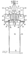
- This embodiment comprises a tubular element or pile 35, preferably made of steel.
- the lower end 36 of the pile 35 is open and is provided with a cutting edge 37.
- the tubular element 35 is furthermore provided with a radial flange 38 which is reinforced by radial webs 39.
- a pumping unit generally indicated by reference numeral 40 is adapted to be placed onto the top end of the tubular element 35.
- a sealing ring 41 is present so that a liquid tight seal can be obtained between the tubular element 35 and the pumping unit 40.
- the pumping unit 10 comprises a hollow main body 42 carrying two pumps 43 respectively 44, each having an outlet 45 respectively 46. Within the main body 42, compartments 47 and 48 are present. These compartments are in communication with the pumps 43 respectively 44.
- Valves 55 respectively 56 are arranged at the end of channel 51 respectively channel 53. These valves are preferably remotely controlled, so that they can be opened or closed at will from a vessel at the watersurface.
- suitable electric cables 60 respectively 61 lead from the valve 55 respectively 56 to the said vessel.
- Electric cables 62 respectively 63 lead from the pumps 43 respectively 44 to the vessel at the watersurface in order to switch the pumps 43 and 44 on and off as required.
- radial webs 64 and 65 are present which carry an eye 66 which is centrally arranged within the tubular element.
- a first hoisting cable 67 is secured to the eye 66.
- An annular guide element 72 is arranged around the hoisting cable 67.
- Hoisting cables 68 and 69 are secured respectively to eyes 70 and 71 on the pump unit 40.
- the electric cables 60 and 62 are secured to or incorporated into the hoisting cable 68 and the electric cables 61 and 63 are secured to or incorporated into hoisting cable 69.
- the tubular element 35 is lowered from a vessel to the waterbottom.
- the cable 67 is slackened somewhat, in order to allow the cutting edge 37 to penetrate into the waterbottom under the weight of the tubular element 35.
- the valves 55 and 56 are opened and the pump unit 40 is lowered from the vessel by means of the cables 68 and 69 until the pump unit 40 reaches the position as shown in Figure 7.
- the guide element 72 slides along the cable 67 which is kept in stretched condition during the lowering of the pump unit 40.
- the remotely controlled valves 55 and 56 are then closed from the vessel by passing a proper signal and the necessary energy via the electric cables to the valves 55 and 56.
- the pumps 43 and/or 44 are switched on by passing a proper signal and the necessary energy through the electric cables 62 and/or 63.
- the pump(s) 43 and/or 44 remove water from the interior 50 of the tubular element 35 which is discharged through the outlet(s) 45 and/or 46. In this manner a pressure difference is created between the interior 50 and the exterior of the tubular element 35 which causes the latter to penetrate into the waterbottom.
- the pumps 43 and/or 44 are switched off and the valves 55 and 56 are opened again. Then by means of the hoisting cables 68 and 69 the pumping unit 40 is raised to the watersurface and taken aboard of the vessel. If desired the cable 67 can then be used for mooring a floating object such as a vessel or a floating platform to the tubular element 35.
- the tubular element 35 is lowered to the waterbottom before the lowering of the pumping unit 40. Instead, it is possible to lower the tubular element 35 and the pumping unit 40 together at the same time.
- a tubular element, secured to the bottom of a body of water in the manner according to the invention can be used for various purposes. If it is provided with an anchor cable, it can for example be used for the mooring of a ship, for anchoring a floating production- or drilling platform, so as for example a so-called tension leg platform, for anchoring a single buoy mooring system for loading or unloading tankers.
- the said tubular element can also be used as an envelope for protecting the well head and/or the upper part of an oil- or gaswell in the seabed, or for anchoring a pipeline to the seabed, or for the staying by means of guy cables of various structures, such as for example a freestanding marine conductor.
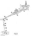
- FIG 8 discloses a bow mooring system for mooring a supply boat 80 close to an offshore drilling platform 81.
- a tubular element 82 secured to the seabottom 83 in the manner according to the invention, is used for anchoring an intermediate buoy 84 below the watersurface 85 by means of a chain or cable 86, which interconnects the tubular element 82 and the intermediate buoy 84.
- a mooring buoy 87 floating at the watersurface 85 is connected to the intermediate buoy 84 by means of a cable or chain 88.
- the mooring buoy 87 is provided with a mooring line 88 which is adapted to be connected to the mooring hawser 89 of the supply boat 80.
- the stern of the boat 80 is connected to the platform 81 by means of a pair of mooring lines 90 and 91.
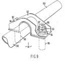
- FIG. 9 Another field of application of the invention concerns the anchoring of a pipeline to the seabed in the manner as shown in Figure 9.
- a pipeline 90 is shown which is laying on the seabed 91.
- a brace 92 is placed over the pipeline 91.
- the brace 92 is provided with a bore 93 and a jacket 94.
- the brace 92 is secured to the seabed by passing through each bore 93 and jacket 94 a tubular element 95 according to the invention.
- This tubular element 95 is provided with a collar 96 and it is installed and caused to penetrate into the seabed 91 in the manner according to the invention as described in the above.
- the jacket 94 is internally provided with a cam 97 which is adapted to cooperate with the collar 96 on the tubular element 95.
- Figure 9 shows the situation after both tubular elements 95 have been installed.
- the tubular elements 95 anchor the brace 92, firmly to the seabed 91, so that the brace 92 secures the pipeline 90 firmly to the seabed 91.
- the purpose of the cam 97 is to load the tubular element 95 eccentrically when an upwardly directed force acts on the pipeline 90 and thus on the brace 92.
- the pump used in the pumping unit according to the invention can be of any suitable type, for example centrifugal pump, a positive displacement pump, or even an ejector pump.
Landscapes
- Chemical & Material Sciences (AREA)
- Engineering & Computer Science (AREA)
- Combustion & Propulsion (AREA)
- Mechanical Engineering (AREA)
- Ocean & Marine Engineering (AREA)
- Earth Drilling (AREA)
- Placing Or Removing Of Piles Or Sheet Piles, Or Accessories Thereof (AREA)
- Jet Pumps And Other Pumps (AREA)
- Toys (AREA)
- Orthopedics, Nursing, And Contraception (AREA)
Claims (2)
Applications Claiming Priority (2)
| Application Number | Priority Date | Filing Date | Title |
|---|---|---|---|
| GB7847094 | 1978-12-04 | ||
| GB4709478 | 1978-12-04 |
Publications (2)
| Publication Number | Publication Date |
|---|---|
| EP0011894A1 EP0011894A1 (fr) | 1980-06-11 |
| EP0011894B1 true EP0011894B1 (fr) | 1984-07-04 |
Family
ID=10501507
Family Applications (1)
| Application Number | Title | Priority Date | Filing Date |
|---|---|---|---|
| EP79200678A Expired EP0011894B1 (fr) | 1978-12-04 | 1979-11-20 | Méthode et appareillage pour l'installation d'un élément tubulaire au fond de l'eau |
Country Status (7)
| Country | Link |
|---|---|
| US (1) | US4318641A (fr) |
| EP (1) | EP0011894B1 (fr) |
| JP (1) | JPS5576280A (fr) |
| AU (1) | AU529277B2 (fr) |
| ES (1) | ES486474A1 (fr) |
| MY (1) | MY8600705A (fr) |
| NO (1) | NO793903L (fr) |
Cited By (23)
| Publication number | Priority date | Publication date | Assignee | Title |
|---|---|---|---|---|
| FR2503084A1 (fr) * | 1981-04-02 | 1982-10-08 | Shell Int Research | Ancre a aspiration et procede pour son installation |
| GB2307708A (en) * | 1995-11-29 | 1997-06-04 | Deep Oil Technology Inc | Deep water piling and methods of installing or removing |
| GB2325017A (en) * | 1997-03-26 | 1998-11-11 | Chevron Usa Inc | Installation of a foundation pile in a subsurface soil |
| US5915326A (en) * | 1996-09-11 | 1999-06-29 | Karal; Karel | Subsea mooring |
| WO1999051821A1 (fr) | 1998-04-02 | 1999-10-14 | Suction Pile Technology B.V. | Structure marine |
| WO1999057009A1 (fr) | 1998-05-06 | 1999-11-11 | Suction Pile Technology B.V. | Ancre marine et technique de mise en place |
| US6113315A (en) * | 1997-10-09 | 2000-09-05 | Aker Marine, Inc. | Recoverable system for mooring mobile offshore drilling units |
| GB2350341A (en) * | 1997-11-01 | 2000-11-29 | Shell Int Research | Rov installed suction piles |
| EP1101872A2 (fr) | 1999-11-18 | 2001-05-23 | Suction Pile Technology B.V. | Structure marine |
| US6719496B1 (en) | 1997-11-01 | 2004-04-13 | Shell Oil Company | ROV installed suction piles |
| EP2216447A1 (fr) | 2009-02-09 | 2010-08-11 | Suction Pile Technology B.V. | Structure marine flottante avec piliers d'aspiration et plateforme reposant sur une barge encastrée entre les piliers d'aspiration et la plateforme |
| WO2011071385A1 (fr) | 2009-12-09 | 2011-06-16 | Suction Pile Technology Bv | Structure marine flottante à piles à succion et bateau |
| WO2012070937A1 (fr) | 2010-11-22 | 2012-05-31 | Suction Pile Technology Bv | Procédé d'installation d'une tour effilée en mer, faisant saillie en hauteur au-dessus de la mer, présentant une fondation à pilier à aspiration |
| WO2014084737A1 (fr) | 2012-11-29 | 2014-06-05 | Suction Pile Technology Bv | Pilier à aspiration à double sommet et fondation de pilier à aspiration |
| EP3222783A1 (fr) | 2016-03-24 | 2017-09-27 | SPT Equipment BV | Structure marine flottante à pieux à succion |
| EP3228754A1 (fr) | 2016-04-05 | 2017-10-11 | SPT Equipment BV | Protection contre l'érosion pour pile à succion, par exemple, pile à abaissement actionné |
| EP3315670A2 (fr) | 2016-04-13 | 2018-05-02 | SPT Equipment BV | Dispositif de pompe pour pieux de succion |
| WO2019074363A1 (fr) | 2017-10-10 | 2019-04-18 | Spt Equipment Bv | Système de fondation d'installation d'énergie éolienne en haute mer |
| WO2021066657A1 (fr) | 2019-10-03 | 2021-04-08 | Spt Equipment Bv | Tête de puits de fond océanique de type à aspiration |
| WO2021066656A1 (fr) | 2019-10-02 | 2021-04-08 | Spt Equipment Bv | Pompe à pile à aspiration excentrique avec appareil de levage articulé |
| WO2021071361A1 (fr) | 2019-10-09 | 2021-04-15 | Spt Equipment Bv | Entretien simultané d'un groupe de godets d'aspiration |
| NL2024228B1 (en) | 2019-11-12 | 2021-07-28 | Spt Equipment Bv | Simultaneous servicing a group of suction buckets. |
| NL2028088A (en) | 2020-04-29 | 2021-11-02 | Spt Equipment Bv | Concrete connector body for an offshore wind turbine. |
Families Citing this family (49)
| Publication number | Priority date | Publication date | Assignee | Title |
|---|---|---|---|---|
| US4575282A (en) * | 1984-06-04 | 1986-03-11 | Pardue Sr James H | System for driving open end pipe piles on the ocean floor using pneumatic evacuation and existing hydrostatic pressure |
| US4572304A (en) * | 1984-07-23 | 1986-02-25 | The Earth Technology Corporation | Portable seabed penetration system |
| SE445473B (sv) * | 1984-11-09 | 1986-06-23 | Offshore Ab J & W | Grundleggningselement foretredesvis avsett for undervattensbruk och anvendning av detta |
| AU580415B2 (en) * | 1985-04-29 | 1989-01-12 | Sofec, Inc. | Mooring and transfer system |
| US4721415A (en) * | 1986-06-06 | 1988-01-26 | Shell Offshore Inc. | Well base in ocean floor |
| GB2200672B (en) * | 1986-09-10 | 1991-01-23 | David Sidney Dallimer | Apparatus for installing marine silos |
| US5197822A (en) * | 1990-11-09 | 1993-03-30 | Parks James M | Emplacement of foraminous piping in non-cohesive subsoils |
| US5855178A (en) * | 1996-03-13 | 1999-01-05 | Aker Marine, Inc. | Taut leg mooring system |
| US5704307A (en) * | 1996-03-13 | 1998-01-06 | Aker Marine, Inc. | Taut leg mooring system |
| US6457908B1 (en) * | 1997-05-06 | 2002-10-01 | Delmar Systems, Inc. | Method and apparatus for suction anchor and mooring deployment and connection |
| AU9227598A (en) * | 1997-09-09 | 1999-03-29 | Fmc Corporation | Suction pile subsea foundation structure |
| JP3096446B2 (ja) * | 1997-09-17 | 2000-10-10 | 本田技研工業株式会社 | ハイブリッド車両の制御装置 |
| US5927904A (en) * | 1997-10-29 | 1999-07-27 | Aker Marine, Inc. | Pumpskid for suction anchors |
| US6122847A (en) * | 1997-11-17 | 2000-09-26 | Aker Marine Contractors, Inc. | Method of and apparatus for installation of plate anchors |
| US5992060A (en) * | 1997-11-17 | 1999-11-30 | Aker Marine, Inc. | Method of and apparatus for anchor installation |
| AU743420B2 (en) * | 1998-05-06 | 2002-01-24 | Delmar Systems, Inc. | Method and apparatus for suction anchor and mooring deployment and connection |
| NO993680L (no) | 1998-07-29 | 2000-01-31 | Philip Head | Forankringsanordning og fremgangsmåte |
| GB2341409B (en) * | 1998-09-08 | 2000-11-01 | John Stephen Baross | Mechanical pipeline span prop with suction anchor foundation |
| US6371695B1 (en) | 1998-11-06 | 2002-04-16 | Exxonmobil Upstream Research Company | Offshore caisson having upper and lower sections separated by a structural diaphragm and method of installing the same |
| NO314133B1 (no) * | 1998-12-07 | 2003-02-03 | Master Marine As | Fremgangsmåte ved lastoverföringsoperasjoner til havs og flyter for transport, installasjon og fjerning av konstruksjonselementer til havs |
| NO309240B1 (no) * | 1999-03-11 | 2001-01-02 | Halliburton As | Fremgangsmåte tilpasset for bruk ved plassering av et sugeanker med en tilordnet ankerkjetting eller lignende på havbunnen, samt anordning ved et slikt sugeanker |
| US6203248B1 (en) * | 2000-02-03 | 2001-03-20 | Atwood Oceanics, Inc. | Sliding-resistant bottom-founded offshore structures |
| US6685396B1 (en) * | 2000-11-16 | 2004-02-03 | Billy J. Bergeron | Method and apparatus for suction anchor and mooring deployment and connection |
| US6443660B1 (en) | 2000-11-27 | 2002-09-03 | Oceaneering International, Inc. | Method and system for manipulating an object located underwater |
| WO2002088475A1 (fr) | 2001-04-26 | 2002-11-07 | Suction Pile Technology B.V. | Structure marine |
| KR100459985B1 (ko) * | 2002-02-15 | 2004-12-04 | (주)대우건설 | 석션파일 앵커 |
| KR100458632B1 (ko) * | 2002-02-15 | 2004-12-03 | (주)대우건설 | 석션 파일의 시공방법 |
| US6659182B1 (en) * | 2002-07-11 | 2003-12-09 | Halliburton Energy Services, Inc. | Retrievable suction embedment chamber assembly |
| AU2003254482A1 (en) * | 2002-07-23 | 2004-02-09 | Philip Head | Seabed installation apparatus |
| US7140319B2 (en) * | 2003-03-04 | 2006-11-28 | Exxonmobil Upstream Research Company | Pile anchor with external vanes |
| GB2414221B (en) * | 2003-03-04 | 2006-05-31 | Exxonmobil Upstream Res Co | Anchor installation system |
| GB2436239B (en) * | 2003-03-04 | 2007-10-31 | Exxonmobil Upstream Res Co | Pile anchor with external vanes |
| US7287935B1 (en) * | 2003-07-16 | 2007-10-30 | Gehring Donald H | Tendon assembly for mooring offshore structure |
| WO2006126884A1 (fr) * | 2005-03-29 | 2006-11-30 | Norse Cutting & Abandonment As | Procede et dispositif pour fixer un appareil de decoupage sous-marin |
| US20080292409A1 (en) | 2005-12-01 | 2008-11-27 | Single Buoy Moorings Inc. | Suction Pile Installation Method and Suction Pile For Use in Said Method |
| US7621059B2 (en) * | 2007-10-18 | 2009-11-24 | Oceaneering International, Inc. | Underwater sediment evacuation system |
| BE1018005A3 (nl) * | 2008-02-18 | 2010-03-02 | Rompay Boudewijn Gabriul Van | Werkwijze voor het verwijderen van slib van de bodem van een watergebied. |
| DE212011100078U1 (de) | 2010-01-26 | 2012-12-12 | Husqvarna Ab | Verlegemaschine |
| NO333844B1 (no) * | 2010-11-09 | 2013-09-30 | Agr Subsea As | Fremgangsmåte for å etablere et borehull i en sjøbunn og et lederør og en sugemodul for utøvelse av fremgangsmåten |
| NO332121B1 (no) * | 2010-11-09 | 2012-07-02 | Aker Subsea As | Havbunnsanker |
| DE102014015801A1 (de) * | 2014-10-24 | 2016-04-28 | Hab Hallen- Und Anlagenbau Gmbh | Sauganker |
| US9446821B1 (en) | 2015-05-21 | 2016-09-20 | Austin MOHRFELD | Port and plug system for subsea equipment |
| BR112018008255B1 (pt) * | 2015-10-22 | 2021-10-19 | Shell Internationale Research Maatschappij B.V. | Dispositivo de fixação de tubo |
| US9789932B2 (en) * | 2015-11-25 | 2017-10-17 | Cameron International Corporation | System and method for installing suction piles |
| US9869071B1 (en) * | 2016-10-08 | 2018-01-16 | Austin T. Mohrfeld | Method for installing a pile |
| JP2022521716A (ja) * | 2019-02-13 | 2022-04-12 | アールシーエイエム テクノロジーズ インコーポレイテッド | 吸引アンカおよび吸引アンカの製造方法 |
| US10988907B1 (en) * | 2020-08-26 | 2021-04-27 | Ician Engineering Contractors Co., Ltd. | Sinking apparatus for sinking concrete shaft |
| GB2611090A (en) * | 2021-09-27 | 2023-03-29 | Equinor Energy As | Method of installing or remediating suction bucket structures for wind turbines |
| BE1030621B1 (nl) * | 2022-06-03 | 2024-01-22 | Deme Offshore Be Nv | Werkwijze voor het in een waterbodem verankeren van een hol buisvormig element, en samenstel van het buisvormige element en een afsluitlichaam |
Family Cites Families (14)
| Publication number | Priority date | Publication date | Assignee | Title |
|---|---|---|---|---|
| US3263641A (en) * | 1964-09-15 | 1966-08-02 | Robert F Patterson | Anchoring structure |
| US3411473A (en) * | 1966-12-19 | 1968-11-19 | Texaco Inc | Deepwater anchor |
| US3431879A (en) * | 1967-08-11 | 1969-03-11 | Gulf Oil Corp | Method and apparatus for offshore anchoring |
| US3496900A (en) * | 1968-05-23 | 1970-02-24 | Texaco Inc | Method for installing a deep water anchor |
| DE1940392A1 (de) * | 1969-08-08 | 1971-02-18 | Erno Raumfahrttechnik Gmbh | Sauganker zur Verankerung von Geraeten in groesseren Tiefen auf dem Meeresboden |
| US3817040A (en) * | 1972-07-03 | 1974-06-18 | E Stevens | Pile driving method |
| FR2335133A5 (fr) * | 1973-03-05 | 1977-07-08 | Sea Tank Co | Procede et dispositif de fondation par depression en site aquatique |
| US4036161A (en) * | 1973-07-04 | 1977-07-19 | The Secretary Of State For Industry In Her Britannic Majesty's Government Of The United Kingdom Of Great Britain & Northern Ireland | Underwater anchoring apparatus |
| FR2247377A1 (en) * | 1973-10-15 | 1975-05-09 | Aerazur Constr Aeronaut | Surface or submarine unit sea anchor - has open bottom suction chamber embedded in sea bed as far as bearing ring |
| GB1451537A (en) * | 1974-04-01 | 1976-10-06 | Langner K E | Method of forming a subaqueous anchorage |
| NL167910C (nl) * | 1974-11-05 | 1982-02-16 | Single Buoy Moorings | Afmeerinrichting. |
| FR2408509A1 (fr) * | 1977-11-14 | 1979-06-08 | United Kingdom Government | Ancre marine a depression |
| GB2010202B (en) * | 1977-11-14 | 1982-06-16 | Secretary Industry Brit | Pinned suction anchors |
| US4215544A (en) * | 1978-05-17 | 1980-08-05 | Tad Stanwick | Method of generating rotary power in a deepsea environment |
-
1979
- 1979-11-20 EP EP79200678A patent/EP0011894B1/fr not_active Expired
- 1979-11-30 ES ES486474A patent/ES486474A1/es not_active Expired
- 1979-11-30 AU AU53363/79A patent/AU529277B2/en not_active Expired
- 1979-11-30 JP JP15451479A patent/JPS5576280A/ja active Granted
- 1979-11-30 US US06/099,240 patent/US4318641A/en not_active Expired - Lifetime
- 1979-11-30 NO NO793903A patent/NO793903L/no unknown
-
1986
- 1986-12-30 MY MY705/86A patent/MY8600705A/xx unknown
Cited By (31)
| Publication number | Priority date | Publication date | Assignee | Title |
|---|---|---|---|---|
| FR2503084A1 (fr) * | 1981-04-02 | 1982-10-08 | Shell Int Research | Ancre a aspiration et procede pour son installation |
| GB2307708A (en) * | 1995-11-29 | 1997-06-04 | Deep Oil Technology Inc | Deep water piling and methods of installing or removing |
| GB2307708B (en) * | 1995-11-29 | 2000-03-08 | Deep Oil Technology Inc | Deep water piling and methods of installing |
| US5915326A (en) * | 1996-09-11 | 1999-06-29 | Karal; Karel | Subsea mooring |
| GB2325017A (en) * | 1997-03-26 | 1998-11-11 | Chevron Usa Inc | Installation of a foundation pile in a subsurface soil |
| GB2325017B (en) * | 1997-03-26 | 2001-08-29 | Chevron Usa Inc | Installation of a foundation pile in a subsurface soil |
| US6309269B1 (en) | 1997-10-09 | 2001-10-30 | Aker Marine, Inc. | Variable buoyancy buoy for mooring mobile offshore drilling units |
| US6113315A (en) * | 1997-10-09 | 2000-09-05 | Aker Marine, Inc. | Recoverable system for mooring mobile offshore drilling units |
| US6719496B1 (en) | 1997-11-01 | 2004-04-13 | Shell Oil Company | ROV installed suction piles |
| GB2350341A (en) * | 1997-11-01 | 2000-11-29 | Shell Int Research | Rov installed suction piles |
| GB2350341B (en) * | 1997-11-01 | 2001-11-28 | Shell Int Research | Rov installed suction piles |
| US6488446B1 (en) | 1998-04-02 | 2002-12-03 | Suction Pile Technology Bv | Marine structure |
| WO1999051821A1 (fr) | 1998-04-02 | 1999-10-14 | Suction Pile Technology B.V. | Structure marine |
| WO1999057009A1 (fr) | 1998-05-06 | 1999-11-11 | Suction Pile Technology B.V. | Ancre marine et technique de mise en place |
| EP1101872A2 (fr) | 1999-11-18 | 2001-05-23 | Suction Pile Technology B.V. | Structure marine |
| US6481932B1 (en) | 1999-11-18 | 2002-11-19 | Suction Pile Technology B.V. | Marine structure |
| EP2216447A1 (fr) | 2009-02-09 | 2010-08-11 | Suction Pile Technology B.V. | Structure marine flottante avec piliers d'aspiration et plateforme reposant sur une barge encastrée entre les piliers d'aspiration et la plateforme |
| WO2011071385A1 (fr) | 2009-12-09 | 2011-06-16 | Suction Pile Technology Bv | Structure marine flottante à piles à succion et bateau |
| WO2012070937A1 (fr) | 2010-11-22 | 2012-05-31 | Suction Pile Technology Bv | Procédé d'installation d'une tour effilée en mer, faisant saillie en hauteur au-dessus de la mer, présentant une fondation à pilier à aspiration |
| EP3690145A1 (fr) | 2012-11-29 | 2020-08-05 | SPT Equipment BV | Pile de succion supérieure double et fondation de pile de succion |
| WO2014084737A1 (fr) | 2012-11-29 | 2014-06-05 | Suction Pile Technology Bv | Pilier à aspiration à double sommet et fondation de pilier à aspiration |
| EP3222783A1 (fr) | 2016-03-24 | 2017-09-27 | SPT Equipment BV | Structure marine flottante à pieux à succion |
| EP3228754A1 (fr) | 2016-04-05 | 2017-10-11 | SPT Equipment BV | Protection contre l'érosion pour pile à succion, par exemple, pile à abaissement actionné |
| EP3315670A2 (fr) | 2016-04-13 | 2018-05-02 | SPT Equipment BV | Dispositif de pompe pour pieux de succion |
| WO2019074363A1 (fr) | 2017-10-10 | 2019-04-18 | Spt Equipment Bv | Système de fondation d'installation d'énergie éolienne en haute mer |
| WO2021066656A1 (fr) | 2019-10-02 | 2021-04-08 | Spt Equipment Bv | Pompe à pile à aspiration excentrique avec appareil de levage articulé |
| WO2021066657A1 (fr) | 2019-10-03 | 2021-04-08 | Spt Equipment Bv | Tête de puits de fond océanique de type à aspiration |
| WO2021071361A1 (fr) | 2019-10-09 | 2021-04-15 | Spt Equipment Bv | Entretien simultané d'un groupe de godets d'aspiration |
| NL2024228B1 (en) | 2019-11-12 | 2021-07-28 | Spt Equipment Bv | Simultaneous servicing a group of suction buckets. |
| NL2028088A (en) | 2020-04-29 | 2021-11-02 | Spt Equipment Bv | Concrete connector body for an offshore wind turbine. |
| WO2021221506A1 (fr) | 2020-04-29 | 2021-11-04 | Spt Equipment Bv | Fondation d'éolienne en mer |
Also Published As
| Publication number | Publication date |
|---|---|
| AU5336379A (en) | 1980-06-05 |
| JPS5576280A (en) | 1980-06-09 |
| EP0011894A1 (fr) | 1980-06-11 |
| AU529277B2 (en) | 1983-06-02 |
| JPS6260524B2 (fr) | 1987-12-16 |
| ES486474A1 (es) | 1980-08-16 |
| NO793903L (no) | 1980-06-05 |
| MY8600705A (en) | 1986-12-31 |
| US4318641A (en) | 1982-03-09 |
Similar Documents
| Publication | Publication Date | Title |
|---|---|---|
| EP0011894B1 (fr) | Méthode et appareillage pour l'installation d'un élément tubulaire au fond de l'eau | |
| US5305703A (en) | Vessel mooring system | |
| KR101348574B1 (ko) | 분리 가능한 바닥부/표면 연결 덕트용의 도킹 부표를 갖는 릴을 포함하는 지지물 | |
| US4432671A (en) | Suction anchor and method of installing a suction anchor | |
| US6113315A (en) | Recoverable system for mooring mobile offshore drilling units | |
| RU2485003C2 (ru) | Плавучая платформа, содержащая турель, снабженную двумя буями, к которым прикреплены якорные линии и соединительные трубопроводы связи с морским дном | |
| US6296421B2 (en) | Emergency dump apparatus for buoyancy air tanks on buoyant riser systems | |
| US5515803A (en) | Method and apparatus for mooring a vessel to a submerged mooring element | |
| CA2646510C (fr) | Systeme et procede de connexion destines a connecter et a deconnecter une unite flottante a et d'une bouee reliee a une installation sous-marine | |
| US3902447A (en) | Mooring system for semisubmersible drilling platform | |
| US3315741A (en) | Method and apparatus for drilling offishore wells | |
| EP0221153B1 (fr) | Systeme et procede d'amarrage et de transfert | |
| CN117810874B (zh) | 一种海底电缆续接抢修装置 | |
| AU2762795A (en) | Method and apparatus for mooring a vessel | |
| RU2226478C2 (ru) | Комплекс для спасения команды затонувшего судна, подъема и буксировки последнего | |
| RU2235039C2 (ru) | Способ спасения команды затонувшего судна, подъема и буксировки последнего | |
| NO313920B1 (no) | Stigerorsystem for anvendelse ved produksjon av hydrokarboner med et fartoy av FPSO-typen med et dynamisk posisjoneringssystem (DP) | |
| AU580415B2 (en) | Mooring and transfer system | |
| RU2135389C1 (ru) | Способ подъема судна с донного грунта | |
| GB2300835A (en) | Method and apparatus for raising a sunken object | |
| MXPA00006318A (en) | Emergency dump apparatus for buoyancy air tanks on buoyant riser systems |
Legal Events
| Date | Code | Title | Description |
|---|---|---|---|
| PUAI | Public reference made under article 153(3) epc to a published international application that has entered the european phase |
Free format text: ORIGINAL CODE: 0009012 |
|
| AK | Designated contracting states |
Designated state(s): FR GB IT NL |
|
| 17P | Request for examination filed |
Effective date: 19801107 |
|
| ITF | It: translation for a ep patent filed | ||
| GRAA | (expected) grant |
Free format text: ORIGINAL CODE: 0009210 |
|
| AK | Designated contracting states |
Designated state(s): FR GB IT NL |
|
| ET | Fr: translation filed | ||
| PLBE | No opposition filed within time limit |
Free format text: ORIGINAL CODE: 0009261 |
|
| STAA | Information on the status of an ep patent application or granted ep patent |
Free format text: STATUS: NO OPPOSITION FILED WITHIN TIME LIMIT |
|
| 26N | No opposition filed | ||
| REG | Reference to a national code |
Ref country code: GB Ref legal event code: 746 |
|
| ITPR | It: changes in ownership of a european patent |
Owner name: OFFERTA DI LICENZA AL PUBBLICO |
|
| REG | Reference to a national code |
Ref country code: FR Ref legal event code: DL |
|
| ITTA | It: last paid annual fee | ||
| PGFP | Annual fee paid to national office [announced via postgrant information from national office to epo] |
Ref country code: FR Payment date: 19980924 Year of fee payment: 20 |
|
| PGFP | Annual fee paid to national office [announced via postgrant information from national office to epo] |
Ref country code: GB Payment date: 19981029 Year of fee payment: 20 |
|
| PGFP | Annual fee paid to national office [announced via postgrant information from national office to epo] |
Ref country code: NL Payment date: 19981126 Year of fee payment: 20 |
|
| PG25 | Lapsed in a contracting state [announced via postgrant information from national office to epo] |
Ref country code: GB Free format text: LAPSE BECAUSE OF EXPIRATION OF PROTECTION Effective date: 19991119 |
|
| PG25 | Lapsed in a contracting state [announced via postgrant information from national office to epo] |
Ref country code: NL Free format text: LAPSE BECAUSE OF EXPIRATION OF PROTECTION Effective date: 19991120 |
|
| REG | Reference to a national code |
Ref country code: GB Ref legal event code: PE20 Effective date: 19991119 |
|
| NLV7 | Nl: ceased due to reaching the maximum lifetime of a patent |
Effective date: 19991120 |