EP0011800A1 - Etching process for copper and copper alloy surfaces - Google Patents
Etching process for copper and copper alloy surfaces Download PDFInfo
- Publication number
- EP0011800A1 EP0011800A1 EP79104575A EP79104575A EP0011800A1 EP 0011800 A1 EP0011800 A1 EP 0011800A1 EP 79104575 A EP79104575 A EP 79104575A EP 79104575 A EP79104575 A EP 79104575A EP 0011800 A1 EP0011800 A1 EP 0011800A1
- Authority
- EP
- European Patent Office
- Prior art keywords
- etching solution
- copper
- iron
- etching
- anode
- Prior art date
- Legal status (The legal status is an assumption and is not a legal conclusion. Google has not performed a legal analysis and makes no representation as to the accuracy of the status listed.)
- Granted
Links
Images


Classifications
-
- C—CHEMISTRY; METALLURGY
- C23—COATING METALLIC MATERIAL; COATING MATERIAL WITH METALLIC MATERIAL; CHEMICAL SURFACE TREATMENT; DIFFUSION TREATMENT OF METALLIC MATERIAL; COATING BY VACUUM EVAPORATION, BY SPUTTERING, BY ION IMPLANTATION OR BY CHEMICAL VAPOUR DEPOSITION, IN GENERAL; INHIBITING CORROSION OF METALLIC MATERIAL OR INCRUSTATION IN GENERAL
- C23F—NON-MECHANICAL REMOVAL OF METALLIC MATERIAL FROM SURFACE; INHIBITING CORROSION OF METALLIC MATERIAL OR INCRUSTATION IN GENERAL; MULTI-STEP PROCESSES FOR SURFACE TREATMENT OF METALLIC MATERIAL INVOLVING AT LEAST ONE PROCESS PROVIDED FOR IN CLASS C23 AND AT LEAST ONE PROCESS COVERED BY SUBCLASS C21D OR C22F OR CLASS C25
- C23F1/00—Etching metallic material by chemical means
- C23F1/46—Regeneration of etching compositions
Definitions
- the invention also relates to a method for etching surfaces made of copper or copper alloys by means of an acidic etching solution containing an oxidizing agent, which after removal of the copper surface flows through an electrolytic cell containing anode and cathode for regeneration of the oxidizing agent, the etched-off copper being deposited on the cathode .
- etching solution The removal of surfaces consisting of copper or containing copper by means of an etching solution is known for the production of printed circuits, plastic plates which are copper-clad on one or both sides being etched off after covering the surfaces forming the circuit with a protective layer with the remaining part of the copper cladding .
- the etching solutions are also used to form the surface of printing rollers. In order to make the processes economical, the used etching solutions are regenerated and reprocessed. The etched-off copper contained in the etching solution is recovered.
- Electrochemical processes are suitable for continuous reprocessing of the etching solution, wherein the etching solution is introduced into an electrolytic cell, at the anode of which the oxidizing agent used for the etching is regenerated.
- iron (III) chloride is used as the etchant, the iron (II) chloride formed during the etching is oxidized to iron (III) chloride.
- etching solutions containing copper (II) chloride as an oxidizing agent can be regenerated.
- the copper (I) chloride contained in the electrolyte solution after the copper surface has been removed is converted back to copper (II) chloride at the anode of the electrolytic cell.
- the disadvantage here is the development of chlorine at the anode, which leads to considerable pollution of the environment and to the consumption of the oxidizing agent.
- the anode compartment contains a sodium hydroxide solution.
- the sodium hydroxide serves to absorb the chlorine which develops at the anode during the regeneration of the etching solution.
- a disadvantage when using iron (III) chloride or copper (II) chloride as the etching solution containing the oxidizing agent is, moreover, the attack by the oxidizing agent of the materials used for the construction of the etching systems, provided that these do not consist of acid-resistant materials such as plastics which, however, are not temperature-resistant.
- the object of the invention is to provide a method for chemical etching of metallic surfaces which chlorine development at the anode is prevented in a simple manner and at the same time the components of the apparatus are no longer chemically attacked, even at higher temperatures.
- the copper should also be removable in solid form when the etching solution is regenerated.
- Iron oxide is suitable. Elgen carbonate or iron ammonium alum. Iron (II) sulfate is preferably added to the etching solution.
- Keble particles are added to the etching solution. Coal parts characterized in claims 4 to 7 are particularly suitable.
- the carbon particles are suspended in the etching solution. When flowing through the electrolysis cell, the carbon particles charge at the anode and transfer electrical charge to the copper surface to be processed. When the particles touch the copper layer, metal ions dissolve, so that the surface is electrochemically removed in addition to chemical etching with iron (III) sulfate.
- the copper ions in solution are deposited on the cathode of the electrolytic cell.
- the method according to the invention therefore enables the copper residues to be removed with a circulating etching solution with immediate recovery of the deposited copper on the cathode without the development of chlorine of the apparatus. *) on the anode of the Clekis lysis cell
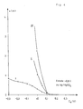
- FIG. 2 shows the copper removal as a function of the iron content of the etching solution.
- Figure 3 shows the current yield achieved as a function of copper and iron content in the solution
- Figure 4 shows the charge transfer in the electrolysis cell.
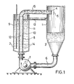
- the device has an etching chamber 1 and an electrolysis cell 2, between which an etching solution 3 is circulated.
- the etching solution is applied to the surface of a workpiece 5 to be processed by means of a spray nozzle 4.
- the used etching solution flows to the bottom of the etching chamber 1. From there it is sucked off by a solvent pump 7 via a suction line 6 and pumped into the electrolytic cell 2.
- a diaphragm or an ion exchange membrane 10 is inserted between the anode 8 and the cathode 9 in the electrolysis cell and separates the cathode space 11 of the electrolysis cell from the anode space 12.
- the anode 8 consists of graphite and is designed as a tube through which the etching solution flows.
- the wall of the graphite tube has openings 14 for the etching solution to the diaphragm or the ion exchange membrane to bring and the ion exchange between the anode compartment 12 and the cathode compartment 11 to enable.
- the recycled etching solution flows out of the anode compartment 12 via a pressure line 15 back to the etching chamber 1.
- etching solution An aqueous, sulfuric acid, iron (III) sulfate solution is used as the etching solution.
- Electrically conductive carbon particles can be suspended in a concentration in the range between 50 and 250 g / l of etching solution in the etching solution felt in the circuit.
- the diaphragm or the ion exchange membrane 10 used in the electrolysis cell is impermeable to the carbon particles.
- the carbon particles are at the anode. 8 of the electrolytic cell are positively charged and transport electrical charge onto the copper surface of the workpiece 5 to be machined. In addition to chemical etching, copper is then also removed electrochemically, the carbon particles releasing their charge.
- the etching rate is increased considerably by adding activated carbon powder particles.
- the rate of etching increases in the same way as in the first embodiment with increasing iron content in the solution.
- the optimum is achieved with a content of 120 g iron per liter of etching solution.
- the current yield decreases with increasing iron content in the etching solution, measured in g Fe / 1. This is counteracted by the copper content in the etching solution, measured in g Cu / 1, and the current density maintained in the electrolysis cell, measured in A / dm 2 .
- the functions shown in FIG. 3, which show the dependence of the current yield on the iron content in the etching solution, apply to constant values of copper content and current density. If the current efficiency reaches the value 0, copper deposition no longer takes place at the cathode.
- Curve I in the diagram shows the charge transfer for a sulfuric acid, but iron-free etching solution which contains 15% by weight activated carbon powder in suspended form.
- Curve II shows the charge transfer for a sulfuric acid etching solution with iron (III) sulfate in a concentration corresponding to 10 g Fe / 1 etching solution.
- the charge transfer for the etching solution with 15 G ew .-% suspended activated carbon powder and iron (III) sulfate in a concentration corresponding to 10 g Fe / 1 finally shows curve III. It can be seen from the diagram that surprisingly high values for the charge transfer in the electrolysis cell are achieved with an etching solution containing sulfuric acid and iron (III) sulfate, in which activated carbon powder particles are suspended.
Landscapes
- Chemical & Material Sciences (AREA)
- Chemical Kinetics & Catalysis (AREA)
- General Chemical & Material Sciences (AREA)
- Engineering & Computer Science (AREA)
- Materials Engineering (AREA)
- Mechanical Engineering (AREA)
- Metallurgy (AREA)
- Organic Chemistry (AREA)
- ing And Chemical Polishing (AREA)
- Mechanical Treatment Of Semiconductor (AREA)
- Crushing And Grinding (AREA)
- Manufacture And Refinement Of Metals (AREA)
Abstract
Description
Die Erfindung bezieht such auf ein Verfahren zum Ätzen von Oberflächen aus Kupfer oder Kupferlegierungen mittels einer sauren, ein Oxidationsmittel enthaltenden Ätzlösung, die nach Abtragen der Kupferoberfläche zur Regeneration des Oxidationsmittels ein Anode und Kathode enthaltende Elektrolysezelle durchströmt, wobei das abgeätzte Kupfer an der Kathode abgeschieden wird.The invention also relates to a method for etching surfaces made of copper or copper alloys by means of an acidic etching solution containing an oxidizing agent, which after removal of the copper surface flows through an electrolytic cell containing anode and cathode for regeneration of the oxidizing agent, the etched-off copper being deposited on the cathode .
Das Abtragen von aus Kupfer bestehenden oder Kupfer enthaltenden Oberflächen mittels einer Ätzlösung ist für die Herstellung gedruckter Schaltungen bekannt, wobei von Kunststoffplatten, die ein- oder doppeltseitig kupferkaschiert sind, nach Abdecken der die Schaltung bildenden Flächen mit einer Schutzschicht der übrige Teil der Kupferkaschierung abzuätzen ist. Die Ätzlösungen werden jedoch auch zur Ausbildung der Oberfläche von Druckereiwalzen eingesetzt. Um die Verfahren wirtschaftlich zu gestalten, werden die verbrauchten Ätzlösungen regeneriert und wieder aufgearbeitet. Dabei wird das in der Ätzlösung enthaltene abgeätzte Kupfer zurückgewonnen.The removal of surfaces consisting of copper or containing copper by means of an etching solution is known for the production of printed circuits, plastic plates which are copper-clad on one or both sides being etched off after covering the surfaces forming the circuit with a protective layer with the remaining part of the copper cladding . However, the etching solutions are also used to form the surface of printing rollers. In order to make the processes economical, the used etching solutions are regenerated and reprocessed. The etched-off copper contained in the etching solution is recovered.
Für eine kontinuierliche Wiederaufarbeitung der Ätzlösung sind elektrochemische Verfahren geeignet, wobei die Ätzlösung in eine Elektrolysezelle eingeführt wird, an deren Anode das zur Ätzung dienende Oxidationsmittel regeneriert wird. Wird Eisen(III)-Chlorid als Ätzmittel verwendet, so wird das beim Ätzen gebildete Eisen(II)-Chlorid zu Eisen(III)-Chlorid oxidiert. In gleicher Weise lassen sich Ätzlösungen die Kupfer(II)-Chlorid als Oxidationsmittel enthalten, regenerieren. Das nach Abtragen der Kupferoberfläche in der Elektrolytlösung enthaltene Kupfer(I)-Chlorid wird an der Anode der Elektrolysezelle wieder in Kupfer(II)-Chlorid überführt. Nachteilig ist dabei jedoch die Chlorentwicklung an der Anode, die zu erheblicher Belastung der Umwelt und zum Verbrauch des Oxidationsmittels führt. Zur Verhinderung der Chlorentwicklung ist es aus DT-OS 2 537 537 bekannt, eine Kupferchlorid als Oxidationsmittel enthaltende Ätzlösung durch Einleiten in einen Kathodenraum einer Elektrolysezelle unter Zugabe von Salzsäure und Wasserstoffperoxid zu regenerieren, wobei der Anodenraum der Elektro- 'lysezelle durch ein Diaphragma vom Kathodenraum getrennt ist. Der Anodenraum enthält eine Natriumhydroxidlösung. Das Natiumhydroxid dient zur Aufnahme des sich an der Anode bei der Regeneration der Ätzlösung entwickelnden Chlors. Es reagiert mit dem Natriumhydroxid unter Bildung von Natriumhypochlorit. Nachteilig ist bei diesem Verfahren der hohe Verbrauch an Chemikalien. Neben Natriumhydroxid muß auch Salzsäure und Wasserstoffperoxid zugesetzt werden, um die Atzbedingungen im der Ätzkammer konstant zu malten. Hachteilig ist darüber hinaus die toxische Wirkung des im Anodenraum gebildeten. Natriumhypochlorite, dessen Verarbeitung aufwendig ist.Electrochemical processes are suitable for continuous reprocessing of the etching solution, wherein the etching solution is introduced into an electrolytic cell, at the anode of which the oxidizing agent used for the etching is regenerated. If iron (III) chloride is used as the etchant, the iron (II) chloride formed during the etching is oxidized to iron (III) chloride. In the same way, etching solutions containing copper (II) chloride as an oxidizing agent can be regenerated. The copper (I) chloride contained in the electrolyte solution after the copper surface has been removed is converted back to copper (II) chloride at the anode of the electrolytic cell. However, the disadvantage here is the development of chlorine at the anode, which leads to considerable pollution of the environment and to the consumption of the oxidizing agent. To prevent the development of chlorine, it is known from DT-
Ein weiteres Verfahren zur Regentration einer Kupfer(II )-Chlorid als Oxidationsmittel enthaltenden Ätzlösung in einer Elektrolysezell wird in der DE-OS 2 650 912 beschrieben. Um die Chlorgasbildung an der Anode zu vermeiden, werden sowohl der Kupiergehalt der zu regenerierenden Ätzlösung als auch das Verhältnis von Kupfer(I)- zu Kupfer(II)-Ionen auf enge Bereiche begrenzt. Auch sind hohe Stromdichten in der Elektrolysezelle erforderlich. Neben einer aufwendigen Regelung zur Einstellung der vorgegebenen Konzentrationsgrenzen ist infolgedessen auch das Abscheiden des abgeätzten Kupfers an der Kathode der Elektrolysezelle erschwert. Es bilden sich im wesentlichen schlammige ,Niederschläge. Nachteilig ist bei Verwendung von Eisen(III)-Chlorid oder Kupfer(II)-Chlorid als Oxidationsmittel enthaltenden Ätzlösung darüber hinaus der durch diese Oxidationsmittel erfolgende Angriff der für den Bau der Ätzanlagen verwendeten Werkstoffe, soweit diese nicht aus säurefesten Materialien, wie beispielsweise Kunststoffen bestehen, die jedoch nicht temperaturbeständig sind.Another process for the re-concentration of an etching solution containing copper (II) chloride as the oxidizing agent in an electrolytic cell is described in DE-OS 2 650 912. In order to avoid chlorine gas formation at the anode, both the copper content of the etching solution to be regenerated and the ratio of copper (I) to copper (II) ions are limited to narrow ranges. High current densities are also required in the electrolysis cell. In addition to a complex regulation for setting the predetermined concentration limits, the deposition of the etched copper on the cathode of the electrolytic cell is consequently made more difficult. Essentially muddy, precipitates form. A disadvantage when using iron (III) chloride or copper (II) chloride as the etching solution containing the oxidizing agent is, moreover, the attack by the oxidizing agent of the materials used for the construction of the etching systems, provided that these do not consist of acid-resistant materials such as plastics which, however, are not temperature-resistant.
Aufgabe der Erfindung ist es, ein Verfahren zum chemischen Ätzen metallischer OberflAchen anzugeben, bei dem eine Chlorentwioklung an der Anode in einfaoher Weise verhindert wird und bei dem zugleich die Bauteile der Apparaturen auch bei höheren Temperaturen chemisch nicht mehr angegriffen werden. Auch soll das Kupfer bei Regeneration der Ätzlösung in fester Form absoheidbar sein.The object of the invention is to provide a method for chemical etching of metallic surfaces which chlorine development at the anode is prevented in a simple manner and at the same time the components of the apparatus are no longer chemically attacked, even at higher temperatures. The copper should also be removable in solid form when the etching solution is regenerated.
Diese Aufgabe wird bei einem Verfahren der oben genannten Art gemäß der Erfindung durch die im Patent-. anspruch 1 angegebenen Maßnahmen gelöst. Durch Verwendung einer ohlorionenfreien, Eisen(III)-Sulfat enthaltenden Ätzlösung entsteht auch nach vollständiger Oxidation des in der verbrauchten Ätzlösung enthaltenden Eisen(II)-Sulfats kein Chlor an der Anode. Es wird vielmehr Sauerstoff entwickelt, der in die Umgebung abgeblasen werden kann. Die erreichbare Ätzgeschwindigkeit ist abhängig vom Eisengehalt der Ätzlösung. Gemäß der Erfindung wird dieser auf maximal 140 g Eisen pro Liter Ätzlösung beschränkt, da sich gezeigt hat, daß bei Überschreiten dieser Konzentration die Ätzgeschwindigkeit wieder abnimmt. In der Elektrolysezelle wird eine Mindeststromdichte aufrechterhalten, damit ausreichende Werte bei der Ausbeute des sich an der Kathode abscheidendem Kupfers gewährleistet sind. Um die Kupferabscheidung zu fördern, wird eine untere Konzentrationsgrenze für den Gehalt an Kupfer in der Ätzlösung aufrechterhalten.This object is achieved in a method of the type mentioned above according to the invention by the in the patent.
In weiterer Ausgestaltung des erfindungsgemäßen Verfahrens ist vorgesehen, der Ätzlösung Eisenverbindungen zuzugeben, die beim Durchströmen der Ätzlösung durch die Elektrelyzezelle an der ![]()
![]()
Geeignet sind Eisenoxid. Elgenkarbonat oder Eisenammoniumallaun. Bevorzugt wird der Ätzlösung Eisen(II)-Sulfat zugegeben.Iron oxide is suitable. Elgen carbonate or iron ammonium alum. Iron (II) sulfate is preferably added to the etching solution.
Maßnahmen, um die Ätz zu steigern, sind in Patentanspruch 4 angegeben. Der Ätzlösung werden elektrisch leitfähige Keblepartikel zugegeben. Besonders geeignet sind in Patentansprüchen 4 bis 7 gekennzeichnete Kohleteilohen. Die Kohlepartikel werden in der Ätzlösung suspendiert. Bei Durchströmen der Elektrolysezelle laden sich die Kohlepartikel an der Anode auf und übertragen elektrische Ladung auf die zu bearbeitende Kupferoberfläche. Bei Berührung der Teilchen an der Kupferschicht gehen Metallionen in Lösung, so daß die Oberfläche zusätzlich zur chemischen Ätzung mit Eisen(III)-Sulfat elektrochemisch abgetragen wird. Die in Lösung gegangenen Kupferionen scheiden sich an der Kathode der Elektrolysezelle wieder ab.Measures to increase the etching are specified in
Das erfindungsgemäße Verfahren ermöglicht daher eine Abtragung der Kupfersohiohten mit einer im Kreislauf geführten Ätzlösung unter unmittelbarer Wiedergewinnung des abgeschiedenen Kupfers an der Kathode ohne die Entwicklung von Chlor.*) Dis Lisen(III)-Sulfat enthaltende Ätzlösung ermögliont darüberhinaus die Verwendung von Edelstahl für der Bau der Apparate.
*) an der Anode der ClekislysezelleThe method according to the invention therefore enables the copper residues to be removed with a circulating etching solution with immediate recovery of the deposited copper on the cathode without the development of chlorine of the apparatus.
*) on the anode of the Clekis lysis cell
Die Erfindung wird anhand einer in Figur 1 der Zeichnung sohematisoh dargestellten Vorriohtung zur Durohführung des Verfahrens näher erläutert. Ausführungsbeispiele werden nachfolgend beschrieben. Der Kupferabtrag in Abhängigkeit vom Eisengehalt der Ätzlösung ist in Figur 2 wiedergegeben. Figur 3 zeigt die erreichte Stromausbeute in Abhängigkeit von Kupfer- und Eisengehalt in der Lösung, Figur 4 die Ladungsübertragung in der Elektrolysezelle.The invention is explained in more detail with reference to a device for performing the method in FIG. 1 of the drawing. Exemplary embodiments are described below. The copper removal as a function of the iron content of the etching solution is shown in FIG. 2. Figure 3 shows the current yield achieved as a function of copper and iron content in the solution, Figure 4 shows the charge transfer in the electrolysis cell.
Wie aus der Zeichnung ersichtlich ist, weist die Vorrichtung eine Ätzkammer 1 und eine Elektrolysezelle 2 auf, zwischen denen eine Ätzlösung 3 im Kreislauf geführt wird. In der Ätzkammer 1 wird die Ätzlösung mittels einer Sprühdüse 4 auf die zu bearbeitende Oberfläche eines Werkstücks 5 aufgebracht. Die verbrauchte Ätzlösung fließt zum Boden der Ätzkammer 1 ab. Von dort wird sie über eine Saugleitung 6 von einer Lösungsmittelpumpe 7 abgesaugt und in die Elektrolysezelle 2 gepumpt. In der Elektrolysezelle ist zwischen Anode 8 und Kathode 9 ein Diaphragma oder eine Ionenaustauschermembran 10 eingesetzt, die den Kathodenraum 11 der Elektrolysezelle vom Anodenraum 12 trennt. Am kathodenraum 11 ist für die im Kathodenraum enthaltene Lösung ein Überlauf 13 vorgesehen, der in die Ätzkammer 1 mündet. Im Ausführungsbeispiel besteht die Anode 8 aus Graphit und ist als Rohr ausgebildet, durch das die Ätzlösung hindurchfließt. Die Wandung des Graphitrohrs weist Durchbrüche 14 auf, um die Ätzlösung an das Diaphragma oder die Ionenaustauschermembran heranzuführen und den Ionenaustausoh zwischen Anodenraum 12 und Kathodenraum 11 zu ermöglichen. An der Kathode 9 soheidet sich Kupfer ab, an der Anode wird das Oxidationsmittel der Ätzlösung regeneriert. Die wiederaufbereitete Ätzlösung strömt aus dem Anodenraum 12 über eine Druckleitung 15 zur Ätzkammer 1 zurück.As can be seen from the drawing, the device has an
Als Ätzlösung wird eine wässrige, schwefelsaure, Eisen(III)-Sulfatlösung verwendet. In die im Kreislauf gefühlte Ätzlösung lassen sich elektrisch leitfähige Kohlepartikel in einer Konzentration im Bereich zwischen 50 und 250 g/1 Ätzlösung suspendieren. Für die Kohlepartikel ist das in der Elektrolysezelle eingesetzte Diaphragma oder die Ionenaustauschermembran 10 undurchlässig. Die Kohlepartikel werden an der Anode. 8 der Elektrolysezelle positiv aufgeladen und transportieren elektrische Ladung auf die zu bearbeitende Kupferoberfläche des Werkstücks 5. Neben der chemischen Ätzung wird dann Kupfer auch elektrochemisch abgetragen, wobei die Kohlepartikel ihre mitgeführte Ladung abgeben.An aqueous, sulfuric acid, iron (III) sulfate solution is used as the etching solution. Electrically conductive carbon particles can be suspended in a concentration in the range between 50 and 250 g / l of etching solution in the etching solution felt in the circuit. The diaphragm or the
In die beschriebene Vorrichtung wurden jeweils 1,4 1 einer 1 molaren schwefelsauren, Eisen(III)-Sulfat enthaltenden Ätzlösung eingegeben. Dabei wurde der Eisengehalt der Lösung von 5 bis auf 150 g Eisen pro Liter Ätzlösung gesteigert. Geätzt wurden aus Kupfer bestehende Werkstücke, auf die die Ätzlösung mit einer Temperatur von 45 °C bei einem Druck von 1,5 bar mittels der Sprühdüse 4 aufgesprüht wurde. Der Durchsatz betrug 1,9 1/min. In der Elektrolysezelle war eine gleichbleibende Potentialdifferenz von circa +340 mV gegenüber einer Referenzelektrode aus Quecksilber/Quecksilbersulfat eingestellt. Es wurde die Geschwindigkeit, mit der das Kupfer von der Werkstückoberfläche abgetragen wird, gemessen. Die ermittelten Werte in mg Kupfer pro Minute (mg Cu/min) sind in Figur 2 über dem Eisengehalt pro Liter Lösung (g Fe/1) aufgetragen, Kurve I.In each case 1.4 l of a 1 molar sulfuric acid etching solution containing iron (III) sulfate were introduced into the device described. The iron content of the solution was increased from 5 to 150 g of iron per liter of etching solution. Workpieces made of copper were etched onto which the etching solution was sprayed at a temperature of 45 ° C. and a pressure of 1.5 bar by means of the
Aus Kurve I ist ersichtlich, daß mit steigendem Eisengehalt die abgetragene Kupfermenge zunimmt, daß jedoch bei etwa 80 g Eisen pro Liter Ätzlösung ein Maximum erreicht wird. Die Abtragungsgeschwindigkeit nimmt dann mit zunehmendem Eisengehalt wieder ab. Optimale Werte für das Abtragen der Kupferschichten lassen sich also bei Eisengehalter zwischen 30 bis 140 g Eisen pro Liter Ätzlösung erzieiten.From curve I it can be seen that the amount of copper removed increases with increasing iron content, but that a maximum is reached at about 80 g of iron per liter of etching solution. The rate of removal then decreases again with increasing iron content. Optimal values for the removal of the copper layers can therefore be achieved with iron contents between 30 to 140 g iron per liter of etching solution.
Der schwefelsauren, Eisen(III)-Sulfat enthaltenden Ätzlösung werden 15 Gew.-% Aktivkohlepulverteilchen zugesetzt. Alle übrigen Parameter werden wie im Ausführungsbeispiel 1 eingestellt. Die erzielten Ätzgeschwindigkeiten sind in Figur 2, Kurve II aufgetragen.15% by weight of activated carbon powder particles are added to the etching solution containing sulfuric acid and iron (III) sulfate. All other parameters are set as in
Wie aus Kurve II ersichtlich ist, wird die Ätzgeschwindigkeit durch Zugabe von Aktivkohlepulverteilchen erheblich erhöht. Dabei nimmt die Ätzgesohwindigkeit in gleicher Weise, wie im ersten Ausführungsbeispiel mit wachsendem Eisengehalt in der Lösung zu. Das Optimum wird bei einem Gehalt von 120 g Eisen pro Liter Ätzlösung erreicht.As can be seen from curve II, the etching rate is increased considerably by adding activated carbon powder particles. The rate of etching increases in the same way as in the first embodiment with increasing iron content in the solution. The optimum is achieved with a content of 120 g iron per liter of etching solution.
In einer schwefelsauren, Eisen(III)-Sulfat enthaltenden Ätzlösung wurden bei verschiedenen Eisengehalten in der Ätzlösung unterschiedliche Kupferkonzentrationen eingestellt. Es wurde die Stromausbeute bezogen auf die Abscheidung von Kupfer an der Kathode bei verschiedenen Stromdichten in der Elektrolysezelle gemessen.In an etching solution containing sulfuric acid and iron (III) sulfate, different copper concentrations were set at different iron contents in the etching solution. The current yield based on the deposition of copper on the cathode was measured at different current densities in the electrolysis cell.
Wie aus Figur 3 ersichtlich ist, nimmt die Stromausbeute mit steigendem Eisengehalt in der Ätzlösung, gemessen in g Fe/1, ab. Dem wirken der Kupfergehalt in der Ätzlösung, gemessen in g Cu/1, und die in der Elektrolysezelle aufrechterhaltene Stromdichte, gemessen in A/dm2 entgegen. Je höher der Kupfergehalt und je höher die Stromdichte eingestellt sind, um so höhere Stromausbeuten werden erzielt. Die in Figur 3 eingezeichneten Funktionen, die die Abhängigkeit der Stromausbeute vom Eisengenalt in der Ätzlösung zeigen, gelten jeweils für konstante Werte Kupfergehalt und Stromdichte. Erreicht die Stromausbeute den Wert 0, findet an der Kathode keine Kupferabscheidung mehr statt.As can be seen from FIG. 3, the current yield decreases with increasing iron content in the etching solution, measured in g Fe / 1. This is counteracted by the copper content in the etching solution, measured in g Cu / 1, and the current density maintained in the electrolysis cell, measured in A / dm 2 . The higher the copper content and the higher the current density, the higher the current efficiency. The functions shown in FIG. 3, which show the dependence of the current yield on the iron content in the etching solution, apply to constant values of copper content and current density. If the current efficiency reaches the
In einer schwefelsauren, Eisen(III)-Sulfat enthaltenden Ätzlösung mit einer Konzentration entsprechend 10 g Fe/1 wurden 15 Gew.-% Aktivkohlepulver suspendiert. An der Anode der Elektrolysezelle wurde eine Potentialdifferenz von + 0,6 V gegenüber einer Referenzelektrode aus Quecksilber/Quecksilbersulfat eingestellt. Es wurde die Ladungsübertragung zwischen Anode der Elektrolysezelle und Ätzlösung in Abhangigkeit vom gesondert gemessenen Potential der Ätzlösung ermittelt. Das Ergebnis ist aus Figur 4 ersichtlich. Zum Vergleich sind im Diagramm auch die erreichbare Ladungstertragung für Ätzlösungen eingetragen, die entweder Eisen(III)-Sulfat als Oxidationsmittel oder nur Aktivkohlepulverteilchen enthalten. Im Diagramm ist die Ladungsübertragung i in Ampere (A) auf der Ordinate, das Potential der Ätzlösung Es in Volt (V) auf der Abszisse aufgetragen.15% by weight of activated carbon powder were suspended in an etching solution containing sulfuric acid and iron (III) sulfate and having a concentration corresponding to 10 g Fe / 1. At the Anode of the electrolytic cell was set to a potential difference of + 0.6 V compared to a reference electrode made of mercury / mercury sulfate. The charge transfer between the anode of the electrolytic cell and the etching solution was determined as a function of the separately measured potential of the etching solution. The result is shown in Figure 4. For comparison, the diagram also shows the charge transfer that can be achieved for etching solutions that contain either iron (III) sulfate as the oxidizing agent or only activated carbon powder particles. In the diagram, the charge transfer i in amperes (A) is plotted on the ordinate, the potential of the etching solution Es in volts (V) on the abscissa.
Kurve I im Diagramm zeigt die Ladungsübertragung für eine schwefelsaure, jedoch eisenfreie Ätzlösung, die in suspendierter Form 15 Gew.-% Aktivkohlepulver enthält. Kurve II zeigt die Ladungsübertragung für eine schwefelsaure Ätzlösung mit Eisen(III)-Sulfat in einer Konzentration entsprechend 10 g Fe/1 Ätzlösung. Die Ladungsübertragung für die Ätzlösung mit 15 Gew.-% suspendiertem Aktivkohlepulver und Eisen(III)-Sulfat in einer Konzentration entsprechend 10 g Fe/1 zeigt schließlich Kurve III. Aus dem Diagramm ist ersichtlich, daß mit einer schwefelsauren, Eisen(III)-Sulfat enthaltenden Ätzlösung, in der Aktivkohlepulverteilchen suspendiert sind, überraschend hohe Werte für die Ladungsübertragung in der Elektrolysezelle erreicht werden.Curve I in the diagram shows the charge transfer for a sulfuric acid, but iron-free etching solution which contains 15% by weight activated carbon powder in suspended form. Curve II shows the charge transfer for a sulfuric acid etching solution with iron (III) sulfate in a concentration corresponding to 10 g Fe / 1 etching solution. The charge transfer for the etching solution with 15 G ew .-% suspended activated carbon powder and iron (III) sulfate in a concentration corresponding to 10 g Fe / 1 finally shows curve III. It can be seen from the diagram that surprisingly high values for the charge transfer in the electrolysis cell are achieved with an etching solution containing sulfuric acid and iron (III) sulfate, in which activated carbon powder particles are suspended.
Claims (7)
Priority Applications (1)
| Application Number | Priority Date | Filing Date | Title |
|---|---|---|---|
| AT79104575T ATE652T1 (en) | 1978-11-22 | 1979-11-19 | METHOD OF ETCHING COPPER OR COPPER ALLOY SURFACES. |
Applications Claiming Priority (2)
| Application Number | Priority Date | Filing Date | Title |
|---|---|---|---|
| DE2850542 | 1978-11-22 | ||
| DE2850542A DE2850542C2 (en) | 1978-11-22 | 1978-11-22 | Process for etching surfaces made of copper or copper alloys |
Publications (2)
| Publication Number | Publication Date |
|---|---|
| EP0011800A1 true EP0011800A1 (en) | 1980-06-11 |
| EP0011800B1 EP0011800B1 (en) | 1982-02-03 |
Family
ID=6055278
Family Applications (1)
| Application Number | Title | Priority Date | Filing Date |
|---|---|---|---|
| EP79104575A Expired EP0011800B1 (en) | 1978-11-22 | 1979-11-19 | Etching process for copper and copper alloy surfaces |
Country Status (8)
| Country | Link |
|---|---|
| US (1) | US4265722A (en) |
| EP (1) | EP0011800B1 (en) |
| JP (1) | JPS5573872A (en) |
| AT (1) | ATE652T1 (en) |
| AU (1) | AU527609B2 (en) |
| BE (1) | BE893883Q (en) |
| CA (1) | CA1152939A (en) |
| DE (1) | DE2850542C2 (en) |
Families Citing this family (16)
| Publication number | Priority date | Publication date | Assignee | Title |
|---|---|---|---|---|
| US4416725A (en) * | 1982-12-30 | 1983-11-22 | International Business Machines Corporation | Copper texturing process |
| DE3539886A1 (en) * | 1985-11-11 | 1987-05-14 | Hoellmueller Maschbau H | METHOD AND DEVICE FOR ETCHING AN AT LEAST PARTLY OF METAL, PREFERABLY COPPER, EXISTING AGENT |
| US4879045A (en) * | 1986-01-13 | 1989-11-07 | Eggerichs Terry L | Method and apparatus for electromagnetically treating a fluid |
| US5531874A (en) * | 1994-06-17 | 1996-07-02 | International Business Machines Corporation | Electroetching tool using localized application of channelized flow of electrolyte |
| GB2293390A (en) * | 1994-09-20 | 1996-03-27 | British Tech Group | Simultaneous etchant regeneration and metal deposition by electrodialysis |
| DE19850530A1 (en) * | 1998-11-03 | 2000-05-25 | Eilenburger Elektrolyse & Umwelttechnik Gmbh | Circulation process for pickling copper and copper alloys |
| US6656370B1 (en) * | 2000-10-13 | 2003-12-02 | Lenora Toscano | Method for the manufacture of printed circuit boards |
| DE10059743A1 (en) * | 2000-12-01 | 2002-06-20 | Rolf Hempelmann | Catalyst separation process |
| SE519898C2 (en) * | 2001-09-10 | 2003-04-22 | Obducat Ab | Ways to etch copper on card and device and electrolyte for carrying out the method |
| DE10326767B4 (en) * | 2003-06-13 | 2006-02-02 | Atotech Deutschland Gmbh | A method of regenerating ferrous etchant solutions for use in etching or pickling copper or copper alloys, and an apparatus for performing the same |
| US20050067378A1 (en) * | 2003-09-30 | 2005-03-31 | Harry Fuerhaupter | Method for micro-roughening treatment of copper and mixed-metal circuitry |
| CN103924243A (en) * | 2013-01-11 | 2014-07-16 | 上海飞凯光电材料股份有限公司 | Etching solution composition |
| EP2754732B1 (en) * | 2013-01-15 | 2015-03-11 | ATOTECH Deutschland GmbH | Aqueous composition for etching of copper and copper alloys |
| CN111971406B (en) | 2018-06-28 | 2021-10-26 | 古河电气工业株式会社 | Copper alloy sheet material, method for producing copper alloy sheet material, and connector using copper alloy sheet material |
| CN108866572A (en) * | 2018-08-27 | 2018-11-23 | 苏碧云 | A kind of iron displacement copper electrolysis cells |
| CN111809184B (en) * | 2020-07-15 | 2022-03-04 | 深圳市祺鑫环保科技有限公司 | Method for recycling regenerated seed liquid |
Citations (3)
| Publication number | Priority date | Publication date | Assignee | Title |
|---|---|---|---|---|
| US3033793A (en) * | 1958-08-13 | 1962-05-08 | Photo Engravers Res Inc | Powderless etching of copper photoengraving plates |
| SU438729A1 (en) * | 1970-07-17 | 1975-01-23 | Предприятие П/Я А-7125 | The method of regeneration of sulphate and chloride pickling solutions of iron |
| DE2641905A1 (en) * | 1976-09-17 | 1978-03-23 | Kutscherenko | Electrolytic regeneration of spent etchant - contg. iron and copper chloride(s), esp. from printed circuit boards mfr. to avoid pollution and increase etching power |
Family Cites Families (5)
| Publication number | Priority date | Publication date | Assignee | Title |
|---|---|---|---|---|
| US3622478A (en) * | 1960-11-14 | 1971-11-23 | Gen Electric | Continuous regeneration of ferric sulfate pickling bath |
| US3974050A (en) * | 1971-10-12 | 1976-08-10 | Kernforschungsanlage Julich Gesellschaft Mit Beschrankter Haftung | Method of and apparatus for processing the surface of bodies |
| US3788915A (en) * | 1972-02-09 | 1974-01-29 | Shipley Co | Regeneration of spent etchant |
| US4153531A (en) * | 1976-08-21 | 1979-05-08 | Kernforschungsanlage Julich Gesellschaft Mit Beschrankter Haftung | Apparatus for electrochemically processing metallic surfaces |
| DE2655137C2 (en) * | 1976-12-04 | 1978-06-08 | Kernforschungsanlage Juelich Gmbh, 5170 Juelich | Process for the electrochemical processing of metallic surfaces |
-
1978
- 1978-11-22 DE DE2850542A patent/DE2850542C2/en not_active Expired
-
1979
- 1979-11-19 EP EP79104575A patent/EP0011800B1/en not_active Expired
- 1979-11-19 AT AT79104575T patent/ATE652T1/en not_active IP Right Cessation
- 1979-11-20 US US06/096,137 patent/US4265722A/en not_active Expired - Lifetime
- 1979-11-22 AU AU53093/79A patent/AU527609B2/en not_active Ceased
- 1979-11-22 JP JP15077979A patent/JPS5573872A/en active Granted
- 1979-11-22 CA CA000340377A patent/CA1152939A/en not_active Expired
-
1982
- 1982-07-20 BE BE0/208628A patent/BE893883Q/en not_active IP Right Cessation
Patent Citations (3)
| Publication number | Priority date | Publication date | Assignee | Title |
|---|---|---|---|---|
| US3033793A (en) * | 1958-08-13 | 1962-05-08 | Photo Engravers Res Inc | Powderless etching of copper photoengraving plates |
| SU438729A1 (en) * | 1970-07-17 | 1975-01-23 | Предприятие П/Я А-7125 | The method of regeneration of sulphate and chloride pickling solutions of iron |
| DE2641905A1 (en) * | 1976-09-17 | 1978-03-23 | Kutscherenko | Electrolytic regeneration of spent etchant - contg. iron and copper chloride(s), esp. from printed circuit boards mfr. to avoid pollution and increase etching power |
Non-Patent Citations (2)
| Title |
|---|
| CHEMICAL ABSTRACTS, Band 82, 1975, Zusammenfassung Nr. 49269b, Seite 415, Columbus, Ohio, US, & SU - A - 438 729 (V.A. RYABIN et al.) (05.05.1974). * Zusammenfassung * * |
| CHEMICAL ABSTRACTS, Band 87, 1977, Zusammenfassung Nr. 42938p, Seite 228, Columbus, Ohio, US, V.P. STEPANOVA: "Improvement in the composition of a solution used for etching gravure printing forms" & Poligr. Prom-st., Ref. Inf. 1976, (12), 45-6. * Zusammenfassung * * |
Also Published As
| Publication number | Publication date |
|---|---|
| DE2850542A1 (en) | 1980-06-04 |
| EP0011800B1 (en) | 1982-02-03 |
| AU527609B2 (en) | 1983-03-10 |
| DE2850542C2 (en) | 1982-07-01 |
| JPS5573872A (en) | 1980-06-03 |
| JPS636632B2 (en) | 1988-02-10 |
| AU5309379A (en) | 1980-05-29 |
| CA1152939A (en) | 1983-08-30 |
| US4265722A (en) | 1981-05-05 |
| ATE652T1 (en) | 1982-02-15 |
| BE893883Q (en) | 1982-11-16 |
Similar Documents
| Publication | Publication Date | Title |
|---|---|---|
| EP0011800B1 (en) | Etching process for copper and copper alloy surfaces | |
| EP0011799B1 (en) | Process and apparatus for regenerating an etching solution containing cupric and/or ferric chloride in an electrolytic cell | |
| DE2537757C3 (en) | Method of reusing an etching solution | |
| DE60002838T2 (en) | METHOD FOR RECOVERING TIN, TIN ALLOYS OR LEAD PLATE LEADING | |
| DE4002700A1 (en) | ELECTROCHEMICALLY MACHINABLE WORKPIECE AND METHOD FOR ELECTROCHEMICALLY WORKING A METAL WORKPIECE | |
| EP0638664A1 (en) | Process and apparatus for regenerating solutions containing metal ions and sulfuric acid | |
| DE2818971A1 (en) | IMPROVED DEVICE AND PROCESS FOR SEPARATING A METAL FROM A SALT | |
| DE1094245B (en) | Lead dioxide electrode for use in electrochemical processes | |
| DE602004009572T2 (en) | METHOD FOR REGENERATING IRON-BASED SOLID SOLUTIONS FOR USE IN THE PAINTING OR REFURBISHING OF COPPER OR COPPER ALLOYS AND DEVICE FOR CARRYING OUT THE METHOD | |
| DE2641905C2 (en) | Process for the regeneration of used etching solutions | |
| DE3139757C2 (en) | Process for the regeneration of aqueous activator solutions containing palladium and tin | |
| EP0240589B1 (en) | Process and apparatus for regenerating an electroless copper-plating bath | |
| DE4407448C2 (en) | Electrolysis process for regenerating an iron (III) chloride or iron (III) sulfate solution, in particular for spray etching steel | |
| EP0115791B1 (en) | Process and apparatus for regenerating a copper-containing etching solution | |
| DE2655137C2 (en) | Process for the electrochemical processing of metallic surfaces | |
| DE2705895C2 (en) | Process for isotope separation | |
| EP0011801B1 (en) | Process for electrochemically machining metal surfaces | |
| EP0141905B1 (en) | Process for the electrochemical compensation of the oxidation in the electrochemical regeneration of copper etching solutions containing chloride | |
| DE3128849C2 (en) | ||
| DE19532784C2 (en) | Electrolysis process for the regeneration of spent iron (III) chloride or iron (III) sulfate etching solutions | |
| DE2838406A1 (en) | PROCESS FOR THE EXTRACTION OF COPPER AND NICKEL FROM ALLOYS | |
| DE2025211A1 (en) | Selective anodic recovery of silver - from scrap by electro - -deposition from aq soln | |
| DE4118725A1 (en) | Electrolytic regeneration of acidic copper etch solns. - using two-compartment cell sepd. by cation-selective membrane for the generation of chlorine@ for oxidising etching agent and oxygen@ | |
| US1913985A (en) | Refining of lead alloys | |
| DE2150748C3 (en) | Method and device for the electrochemical machining of the surfaces of solid bodies |
Legal Events
| Date | Code | Title | Description |
|---|---|---|---|
| PUAI | Public reference made under article 153(3) epc to a published international application that has entered the european phase |
Free format text: ORIGINAL CODE: 0009012 |
|
| AK | Designated contracting states |
Designated state(s): AT BE CH FR GB IT NL SE |
|
| 17P | Request for examination filed |
Effective date: 19801031 |
|
| ITF | It: translation for a ep patent filed |
Owner name: STUDIO JAUMANN |
|
| GRAA | (expected) grant |
Free format text: ORIGINAL CODE: 0009210 |
|
| AK | Designated contracting states |
Designated state(s): AT BE CH FR GB IT NL SE |
|
| PG25 | Lapsed in a contracting state [announced via postgrant information from national office to epo] |
Ref country code: BE Effective date: 19820203 |
|
| REF | Corresponds to: |
Ref document number: 652 Country of ref document: AT Date of ref document: 19820215 Kind code of ref document: T |
|
| PGFP | Annual fee paid to national office [announced via postgrant information from national office to epo] |
Ref country code: SE Payment date: 19841231 Year of fee payment: 6 |
|
| PGFP | Annual fee paid to national office [announced via postgrant information from national office to epo] |
Ref country code: AT Payment date: 19861008 Year of fee payment: 8 |
|
| PGFP | Annual fee paid to national office [announced via postgrant information from national office to epo] |
Ref country code: NL Payment date: 19871130 Year of fee payment: 9 |
|
| PG25 | Lapsed in a contracting state [announced via postgrant information from national office to epo] |
Ref country code: AT Effective date: 19881119 |
|
| PG25 | Lapsed in a contracting state [announced via postgrant information from national office to epo] |
Ref country code: SE Effective date: 19881120 |
|
| PG25 | Lapsed in a contracting state [announced via postgrant information from national office to epo] |
Ref country code: NL Effective date: 19890601 |
|
| NLV4 | Nl: lapsed or anulled due to non-payment of the annual fee | ||
| EUG | Se: european patent has lapsed |
Ref document number: 79104575.0 Effective date: 19890725 |
|
| PGFP | Annual fee paid to national office [announced via postgrant information from national office to epo] |
Ref country code: GB Payment date: 19971103 Year of fee payment: 19 |
|
| PGFP | Annual fee paid to national office [announced via postgrant information from national office to epo] |
Ref country code: FR Payment date: 19971117 Year of fee payment: 19 |
|
| PGFP | Annual fee paid to national office [announced via postgrant information from national office to epo] |
Ref country code: CH Payment date: 19971125 Year of fee payment: 19 |
|
| PG25 | Lapsed in a contracting state [announced via postgrant information from national office to epo] |
Ref country code: GB Free format text: LAPSE BECAUSE OF NON-PAYMENT OF DUE FEES Effective date: 19981119 |
|
| PG25 | Lapsed in a contracting state [announced via postgrant information from national office to epo] |
Ref country code: CH Free format text: LAPSE BECAUSE OF NON-PAYMENT OF DUE FEES Effective date: 19981130 |
|
| GBPC | Gb: european patent ceased through non-payment of renewal fee |
Effective date: 19981119 |
|
| REG | Reference to a national code |
Ref country code: CH Ref legal event code: PL |
|
| PG25 | Lapsed in a contracting state [announced via postgrant information from national office to epo] |
Ref country code: FR Free format text: LAPSE BECAUSE OF NON-PAYMENT OF DUE FEES Effective date: 19990730 |
|
| REG | Reference to a national code |
Ref country code: FR Ref legal event code: ST |
|
| PLBE | No opposition filed within time limit |
Free format text: ORIGINAL CODE: 0009261 |
|
| STAA | Information on the status of an ep patent application or granted ep patent |
Free format text: STATUS: NO OPPOSITION FILED WITHIN TIME LIMIT |