EP0010342A1 - Vorrichtung zur gewichtsdosierten Fütterung von Tieren - Google Patents
Vorrichtung zur gewichtsdosierten Fütterung von Tieren Download PDFInfo
- Publication number
- EP0010342A1 EP0010342A1 EP79300861A EP79300861A EP0010342A1 EP 0010342 A1 EP0010342 A1 EP 0010342A1 EP 79300861 A EP79300861 A EP 79300861A EP 79300861 A EP79300861 A EP 79300861A EP 0010342 A1 EP0010342 A1 EP 0010342A1
- Authority
- EP
- European Patent Office
- Prior art keywords
- valve
- weight
- container
- bracket
- valve means
- Prior art date
- Legal status (The legal status is an assumption and is not a legal conclusion. Google has not performed a legal analysis and makes no representation as to the accuracy of the status listed.)
- Granted
Links
- 239000000463 material Substances 0.000 claims abstract description 30
- 230000005484 gravity Effects 0.000 claims abstract description 3
- 230000007423 decrease Effects 0.000 claims 1
- 230000007246 mechanism Effects 0.000 abstract description 14
- 244000144972 livestock Species 0.000 description 3
- 244000144977 poultry Species 0.000 description 3
- 241001465754 Metazoa Species 0.000 description 2
- 230000009471 action Effects 0.000 description 1
- 230000004927 fusion Effects 0.000 description 1
- 239000000843 powder Substances 0.000 description 1
- 230000008569 process Effects 0.000 description 1
Images


Classifications
-
- A—HUMAN NECESSITIES
- A01—AGRICULTURE; FORESTRY; ANIMAL HUSBANDRY; HUNTING; TRAPPING; FISHING
- A01K—ANIMAL HUSBANDRY; AVICULTURE; APICULTURE; PISCICULTURE; FISHING; REARING OR BREEDING ANIMALS, NOT OTHERWISE PROVIDED FOR; NEW BREEDS OF ANIMALS
- A01K5/00—Feeding devices for stock or game ; Feeding wagons; Feeding stacks
- A01K5/02—Automatic devices
- A01K5/0275—Automatic devices with mechanisms for delivery of measured doses
- A01K5/0283—Automatic devices with mechanisms for delivery of measured doses by weight
-
- A—HUMAN NECESSITIES
- A01—AGRICULTURE; FORESTRY; ANIMAL HUSBANDRY; HUNTING; TRAPPING; FISHING
- A01K—ANIMAL HUSBANDRY; AVICULTURE; APICULTURE; PISCICULTURE; FISHING; REARING OR BREEDING ANIMALS, NOT OTHERWISE PROVIDED FOR; NEW BREEDS OF ANIMALS
- A01K5/00—Feeding devices for stock or game ; Feeding wagons; Feeding stacks
- A01K5/02—Automatic devices
-
- G—PHYSICS
- G01—MEASURING; TESTING
- G01G—WEIGHING
- G01G13/00—Weighing apparatus with automatic feed or discharge for weighing-out batches of material
- G01G13/02—Means for automatically loading weigh pans or other receptacles, e.g. disposable containers, under control of the weighing mechanism
- G01G13/022—Material feeding devices
- G01G13/024—Material feeding devices by gravity
-
- G—PHYSICS
- G01—MEASURING; TESTING
- G01G—WEIGHING
- G01G13/00—Weighing apparatus with automatic feed or discharge for weighing-out batches of material
- G01G13/16—Means for automatically discharging weigh receptacles under control of the weighing mechanism
- G01G13/18—Means for automatically discharging weigh receptacles under control of the weighing mechanism by valves or flaps in the container bottom
Definitions
- the present invention relates generally to weight actuated feed drop apparatus for dispensing a certain amount of material into a container from a conveyor system.
- the invention provides a weight actuated feed drop apparatus which includes a bracket adapted to be attached to a conveyor system and having an inlet opening therein for receiving material from the conveyor system, and an outlet opening for allowing the material to exit from the bracket by gravity.
- a . valving mechanism is pivotally attached along an axis to the bracket for movement between a first position wherein the valve mechanism closes the outlet opening of the bracket and a second position wherein the valve mechanism is open to allow material to pass from the conveyor system, through the bracket-, to a container disposed below the bracket.
- a projection on the valve mechanism is provided for automatically increasing the closing force on the valve mechanism as it closes.
- One end of a flexible line is attached to the valve mechanism and extends over the projection.
- the other end of the ling is attached to the container for holding the container, whereby a predetermined amount of material by weight is automatically dispensed into the container, upon which event the valve mechanism automatically closes to ensure that no more than the desired weight of material is disclaimedd.
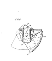
- Fig. 1 shows a weight actuated feed. drop apparatus 10 according to the invention.
- the apparatus is used in conjunction with a conveyor system including a tube 12, for example as disclosed in U.S. Patent Nos. 2738765 and 3905473.
- the apparatus includes a tube bracket 14 which is fastened with clamps 16 to the conveyor tube 12 so that a hole 18 (fig. 4) in the tube bracket 14 is directly beneath the hole in conveyor system 12.
- a valve member 20 Interposed between the tube bracket and the conveyor system is a valve member 20, which when rotated open, exposes the weight actuated valve gate 22 to the material delivered by the conveyor system.
- This valve 20 is more fully disclosed in U.S. Patent No. 4031857.
- the heart of the apparatus is a weight actuated valve 24 (Fig. 2), which is attached to the tube bracket 14 by inserting bosses 26 (Figs. 3,5) into corresponding holes in the tube bracket 14.
- the weight actuated valve 24 includes a housing 28 (Fig. 1) situated on one side of a fulcrum 30 (Fig. 4), with portions of the weight actuated valve 24 situated on the other side.
- valve member 20 and the weight actuated valve 24 are open and the valve member 34 (Fig. 1) is closed, material delivered by the conveyor system falls through a hole/(Fig. 3) in the top of housing 28 and accumulates therein.
- the weight actuated valve 24 closes automatically, as discussed hereinafter, when the weight of the accumulated material in housing 28 equals the weight valve preset on the valve 24. Once closed, the weight actuated valve 24 remains closed and the accumulated material remains in the housing.28 until valve gate 34 (Fig. 1) is opened.
- valve gate 34 if valve gate 34 is opened, the accumulated material, represented by the dashed lines in Fig. 1, flows out downwardly from the housing 28. This action reduces the weight on the housing side of the fulcrum causing the weight actuated valve 24 to open.
- Valve member 20, housing 28, and valve gate 34 are clearly disclosed in U.S. Patent No. 4031857 mentioned above.
- a key element in the weight actuated valve 24 is the pivot member 36 (Figs. 3,5). It has three functions.
- ends 38 (Fig. 3) have slots 39 (Fig. 5) located transversely to fulcrum 30 so as to allow the gross calibration bar 40 (Fig. 3) and the fine calibration bar 42 (Figs. 1 and 3) to slide in a direction parallel to the conveyor tube 12 when the weight, actuated valve 24 is open. Bars 40 and 42 are held in a fixed position relative to pivot member 36 by set screws 44 (Figs. 1 and 2).
- the axle portion 46 (Fig. 2) is shaped so ropes 48 may be fastened to notches 50 (Fig. 5) on one side of the axle", and wrapped over the top and fastened to housing 28 on the other side by extending the ends 49 through openings in the wall of housing 28 and then tying a knot in ends 49 as shown in Figs. 1,2 and 4.
- the axle portion 46 is a further shaped so the weight of housing 28 acts through a short moment arm, distance x (Fig. 4) when valve 24 is open and through a long moment arm, distance Y (Fig. 4), when the valve 24 is closed. Since the distance Y is significantly greater than distance X, valve gate 22 operates to close rapidly when the weight of the accumulated material equals the preset, weight.
- the distance Y is at least three times greater than the distance X.
- valve gate 22 (Fig. 5) is the central portion of pivot member 36. As shown in Fig. 6, it is shaped to enhance a rapid open/closefeature of the valve 24 by substantially offsetting a distance S, the radius, R, of the gate from fulcrum 30. Due to this offset, gate 22 expands open, that is gat 3 22 moves away from and uncovers hole 18 more rapidly than it would if it merely slid along an imaginary circle of which the gate were bLt a part. In other words it is an important feature of the preferred embodiment of the invention that the radius R of the gate 22 from axis point 35 to 37 is substantially greater than the pivotal axis from the point 30 to the point 37.
- the bar 42 is set at zero (0). That is done by loosening the set screw 44, sliding the bar 42 in groove 39 until the pointer 41 (Fig. 6) is pointing at zero on the scale affixed to bar 42. Then the set screw 44 is tightened against the bar 42 to hold it firmly in place.
- valve 24 Once this has been accomplished, the set screw 44 on the other side of valve 24 is loosened, the tare weight bar 40 is slid one way or the other until the balance point is found, that is, the point at which the valve 24 just begins to open or just begins to close (depending upon whether bar 40 is too much one way or the other way when this calibration procedure begins) at which time the set screw 44 for bar 40 is tightened down to securely hold the bar 40 in place with respect to slot 39 in valve 24.
- the apparatus once calibrated to zero, is then ready for operation.
- the scale 43 on bar 42 has one scale on the lower portion of the outside which is in pounds, for example, and another scale which appears up-side-down in Fig. 1, whith is a metric weight scale for example.
- the scale in actunl use is the one which is right side up and the one which is upside down will be ignored. If it is desired to switch from one scale to the other, the set screw 44 is laosanet, the bar 42 is slid out of slot 39, turned over and reinserted in slot 39 such that the scale desired to be used appears right side up and the scale not to be used appears upside down. Once properly positioned the bar 42 would be secured in place by again tightening the appropriate set-screw 44.
- the bar 42 is then set at a desired weight, for example at two pounds, again by using a set screw 44 and sliding it in slot 39 as described above.
- a desired weight for example at two pounds
- the valve 24 will be in the open position as shown in solid lines in Fiq. 1, and the gate 34 of container 28 will be in the closed position as shown in solid lines in Fig. 1.
- the conveyor system will then be operated to cause a granular or powdery material to flow through the tube 12 and drop into the container 28 as is well known.
- a granular or powdery material to flow through the tube 12 and drop into the container 28 as is well known.
- the valve 24 will close to the position shown in dashed lines in Fig.1 and solid lines in Fig. 4.
- the lever arm is a distance X and onse it begins to turn, the effective lever arm quickly lengtiens and becomes the distance Y, which causes an increasing force to be applied to ensure positive closing of the valve gate 22.
- a most common usage of the apparatus of the invention is in a poultry or livestock building in which manYdevices are used to feed individual pens of birds or animals. Consequently all of such containers 28 can be filled to whatever setting is set on individual ones of these devices. Then when it is desired to feed these m asured portions 33 to the poultry or livestock, the cable 35 is pulled (manually or automatically) to allow the feed or other material 33 to drop out of the container 28 to a pan or the like (not shown). When this occurs, the weight transmitted through ropes 48 is insufficient to hold the valve 24 closed and the weight of bar 42 causes the valve 24 to automatically open. The device is then reset to operate automatically again as described above.
- a cable 37 can be utilized to open a large number of gates 34 on an equal number of devices 10 if desired, and each will automatically be reset when the material 33 drops out of the containers 28.
- An individual unit 10 installed in such a system can be utilized merely by opening valve 20.
- the valve 20 can be manually closed and an individual unit 10 not used, for example if there was not a bird or animal to feed in the particular pen wherein such individual unit 10 is installed.
- the apparatus 10 while particularly adapted for use with a feed conveyor system 12, would equally be adapted for handling any kind of powder or grandular material.
Landscapes
- Life Sciences & Earth Sciences (AREA)
- Environmental Sciences (AREA)
- Birds (AREA)
- Animal Husbandry (AREA)
- Biodiversity & Conservation Biology (AREA)
- Physics & Mathematics (AREA)
- General Physics & Mathematics (AREA)
- Filling Or Emptying Of Bunkers, Hoppers, And Tanks (AREA)
- Feeding And Watering For Cattle Raising And Animal Husbandry (AREA)
- Weight Measurement For Supplying Or Discharging Of Specified Amounts Of Material (AREA)
- Sorting Of Articles (AREA)
Applications Claiming Priority (2)
| Application Number | Priority Date | Filing Date | Title |
|---|---|---|---|
| US942675 | 1978-09-15 | ||
| US05/942,675 US4180136A (en) | 1978-09-15 | 1978-09-15 | Weight actuated feed drop apparatus |
Publications (2)
| Publication Number | Publication Date |
|---|---|
| EP0010342A1 true EP0010342A1 (de) | 1980-04-30 |
| EP0010342B1 EP0010342B1 (de) | 1982-02-24 |
Family
ID=25478444
Family Applications (1)
| Application Number | Title | Priority Date | Filing Date |
|---|---|---|---|
| EP79300861A Expired EP0010342B1 (de) | 1978-09-15 | 1979-05-17 | Vorrichtung zur gewichtsdosierten Fütterung von Tieren |
Country Status (7)
| Country | Link |
|---|---|
| US (1) | US4180136A (de) |
| EP (1) | EP0010342B1 (de) |
| JP (1) | JPS5548091A (de) |
| AU (1) | AU521065B2 (de) |
| CA (1) | CA1096804A (de) |
| DE (1) | DE2962177D1 (de) |
| DK (1) | DK169479A (de) |
Cited By (2)
| Publication number | Priority date | Publication date | Assignee | Title |
|---|---|---|---|---|
| GB2154415A (en) * | 1984-01-26 | 1985-09-11 | Fullwood & Bland Limited R J | Dispensers |
| EP3160223A4 (de) * | 2014-06-24 | 2018-02-28 | Daltec A/S | Vorschubkasten |
Families Citing this family (6)
| Publication number | Priority date | Publication date | Assignee | Title |
|---|---|---|---|---|
| AU630682B2 (en) * | 1989-03-30 | 1992-11-05 | Jenkins, Gregory Ivans | Feed system |
| ES2149666B1 (es) * | 1997-10-15 | 2001-06-01 | Guardia Gener Romeu | Dosificador para pienso. |
| US6276517B1 (en) | 2000-01-03 | 2001-08-21 | Protoco, Inc | Ice conveyor |
| NL1015403C2 (nl) * | 2000-06-09 | 2002-01-04 | Lely Entpr Ag | Inrichting voor het automatisch uitnemen en verplaatsen van een hoeveelheid voer, zoals bijvoorbeeld kuilgras of hooi. |
| US6659040B1 (en) | 2002-05-16 | 2003-12-09 | Paul Decker | Self-metering feed dispensing system |
| US20040129229A1 (en) * | 2003-01-08 | 2004-07-08 | Michel Blais | Wall hung automated pet feeding machine |
Citations (6)
| Publication number | Priority date | Publication date | Assignee | Title |
|---|---|---|---|---|
| FR603454A (fr) * | 1925-09-21 | 1926-04-16 | M I A Ets Sa | Dispositif pour balance automatique, rendant indépendante la commande de la vanne d'admission du produit et la commande du déversement du plateau recevant le produit pesé |
| DE1607300A1 (de) * | 1966-09-08 | 1970-06-04 | Gerhard Niemoeller | Dosiervorrichtung fuer Futtermittel in Schweinestaellen |
| DE1657626A1 (de) * | 1968-02-15 | 1971-02-25 | Heinrich Kordel | Viehfuetterungsvorrichtung mit automatischer Dosiereinrichtung |
| AT290156B (de) * | 1969-06-27 | 1971-05-25 | Leopold Kandler | Wiegevorrichtung |
| AT307796B (de) * | 1971-01-14 | 1973-06-12 | Franz Lugmair Fa | Einrichtung zur gewichtsdosierten Fütterung von Tieren |
| US4031857A (en) * | 1976-03-15 | 1977-06-28 | Intraco, Inc. | Volumetric accumulating device |
Family Cites Families (3)
| Publication number | Priority date | Publication date | Assignee | Title |
|---|---|---|---|---|
| US2681639A (en) * | 1950-05-29 | 1954-06-22 | Thurland C Littlefield | Automatic poultry feeder |
| US3254729A (en) * | 1963-09-11 | 1966-06-07 | Behlen Mfg Company Inc | Automatic material unloading system |
| US3869006A (en) * | 1972-08-25 | 1975-03-04 | Chore Time Equipment | Weight controlled feeder system |
-
1978
- 1978-09-15 US US05/942,675 patent/US4180136A/en not_active Expired - Lifetime
-
1979
- 1979-03-20 AU AU45267/79A patent/AU521065B2/en not_active Ceased
- 1979-04-05 CA CA324,942A patent/CA1096804A/en not_active Expired
- 1979-04-25 DK DK169479A patent/DK169479A/da not_active IP Right Cessation
- 1979-05-04 JP JP5515979A patent/JPS5548091A/ja active Granted
- 1979-05-17 EP EP79300861A patent/EP0010342B1/de not_active Expired
- 1979-05-17 DE DE7979300861T patent/DE2962177D1/de not_active Expired
Patent Citations (6)
| Publication number | Priority date | Publication date | Assignee | Title |
|---|---|---|---|---|
| FR603454A (fr) * | 1925-09-21 | 1926-04-16 | M I A Ets Sa | Dispositif pour balance automatique, rendant indépendante la commande de la vanne d'admission du produit et la commande du déversement du plateau recevant le produit pesé |
| DE1607300A1 (de) * | 1966-09-08 | 1970-06-04 | Gerhard Niemoeller | Dosiervorrichtung fuer Futtermittel in Schweinestaellen |
| DE1657626A1 (de) * | 1968-02-15 | 1971-02-25 | Heinrich Kordel | Viehfuetterungsvorrichtung mit automatischer Dosiereinrichtung |
| AT290156B (de) * | 1969-06-27 | 1971-05-25 | Leopold Kandler | Wiegevorrichtung |
| AT307796B (de) * | 1971-01-14 | 1973-06-12 | Franz Lugmair Fa | Einrichtung zur gewichtsdosierten Fütterung von Tieren |
| US4031857A (en) * | 1976-03-15 | 1977-06-28 | Intraco, Inc. | Volumetric accumulating device |
Cited By (2)
| Publication number | Priority date | Publication date | Assignee | Title |
|---|---|---|---|---|
| GB2154415A (en) * | 1984-01-26 | 1985-09-11 | Fullwood & Bland Limited R J | Dispensers |
| EP3160223A4 (de) * | 2014-06-24 | 2018-02-28 | Daltec A/S | Vorschubkasten |
Also Published As
| Publication number | Publication date |
|---|---|
| EP0010342B1 (de) | 1982-02-24 |
| JPS6332417B2 (de) | 1988-06-29 |
| AU521065B2 (en) | 1982-03-11 |
| JPS5548091A (en) | 1980-04-05 |
| AU4526779A (en) | 1980-03-20 |
| DE2962177D1 (en) | 1982-03-25 |
| CA1096804A (en) | 1981-03-03 |
| DK169479A (da) | 1980-03-16 |
| US4180136A (en) | 1979-12-25 |
Similar Documents
| Publication | Publication Date | Title |
|---|---|---|
| EP0010342A1 (de) | Vorrichtung zur gewichtsdosierten Fütterung von Tieren | |
| CA1057691A (en) | Volumetric accumulating device | |
| US6732597B1 (en) | Precision gravimetric feeder | |
| JPS6044834A (ja) | 秤量装置 | |
| US4974548A (en) | Adjustable feeder for livestock | |
| US3166219A (en) | Remote controlled metering device for feed dispensers | |
| US2561721A (en) | Device for dispensing measured quantities of granular materials | |
| US6462288B1 (en) | Metering device | |
| US4130223A (en) | Feed level monitor and control apparatus | |
| US4399931A (en) | Dry material dispenser | |
| US4063666A (en) | Volume metering device having a float operated valve | |
| US1039471A (en) | Automatic grain-weigher. | |
| US1139831A (en) | Measuring device. | |
| EP0426724A1 (de) | Verfahren und anlage zur dosierung und verteilung von futter. | |
| RU1796909C (ru) | Дозатор дл сыпучих материалов | |
| RU2026534C1 (ru) | Устройство для весового дозирования сыпучих материалов | |
| IE43812B1 (en) | A granular material dispenser | |
| US1243791A (en) | Automatic scale. | |
| US1189416A (en) | Automatic scale. | |
| IE80809B1 (en) | Apparatus for dispensing material especially granular material | |
| GB2161282A (en) | Dispensing fluent material | |
| US3193033A (en) | Measuring dispenser | |
| US386745A (en) | Tekritoby | |
| RU1795295C (ru) | Объемный дозатор | |
| US1368778A (en) | Automatic scale |
Legal Events
| Date | Code | Title | Description |
|---|---|---|---|
| PUAI | Public reference made under article 153(3) epc to a published international application that has entered the european phase |
Free format text: ORIGINAL CODE: 0009012 |
|
| AK | Designated contracting states |
Designated state(s): BE DE FR GB IT NL SE |
|
| 17P | Request for examination filed | ||
| ITF | It: translation for a ep patent filed | ||
| GRAA | (expected) grant |
Free format text: ORIGINAL CODE: 0009210 |
|
| AK | Designated contracting states |
Designated state(s): BE DE FR GB IT NL SE |
|
| REF | Corresponds to: |
Ref document number: 2962177 Country of ref document: DE Date of ref document: 19820325 |
|
| PGFP | Annual fee paid to national office [announced via postgrant information from national office to epo] |
Ref country code: GB Payment date: 19900508 Year of fee payment: 12 |
|
| PGFP | Annual fee paid to national office [announced via postgrant information from national office to epo] |
Ref country code: SE Payment date: 19900516 Year of fee payment: 12 Ref country code: DE Payment date: 19900516 Year of fee payment: 12 |
|
| PGFP | Annual fee paid to national office [announced via postgrant information from national office to epo] |
Ref country code: BE Payment date: 19900521 Year of fee payment: 12 |
|
| PGFP | Annual fee paid to national office [announced via postgrant information from national office to epo] |
Ref country code: FR Payment date: 19900530 Year of fee payment: 12 |
|
| ITTA | It: last paid annual fee | ||
| PGFP | Annual fee paid to national office [announced via postgrant information from national office to epo] |
Ref country code: NL Payment date: 19900531 Year of fee payment: 12 |
|
| PG25 | Lapsed in a contracting state [announced via postgrant information from national office to epo] |
Ref country code: GB Effective date: 19910517 |
|
| PG25 | Lapsed in a contracting state [announced via postgrant information from national office to epo] |
Ref country code: SE Effective date: 19910518 |
|
| PG25 | Lapsed in a contracting state [announced via postgrant information from national office to epo] |
Ref country code: BE Effective date: 19910531 |
|
| BERE | Be: lapsed |
Owner name: INTRACO INC. Effective date: 19910531 |
|
| PG25 | Lapsed in a contracting state [announced via postgrant information from national office to epo] |
Ref country code: NL Effective date: 19911201 |
|
| GBPC | Gb: european patent ceased through non-payment of renewal fee | ||
| NLV4 | Nl: lapsed or anulled due to non-payment of the annual fee | ||
| PG25 | Lapsed in a contracting state [announced via postgrant information from national office to epo] |
Ref country code: FR Effective date: 19920131 |
|
| PG25 | Lapsed in a contracting state [announced via postgrant information from national office to epo] |
Ref country code: DE Effective date: 19920303 |
|
| REG | Reference to a national code |
Ref country code: FR Ref legal event code: ST |
|
| EUG | Se: european patent has lapsed |
Ref document number: 79300861.6 Effective date: 19911209 |
|
| PLBE | No opposition filed within time limit |
Free format text: ORIGINAL CODE: 0009261 |
|
| STAA | Information on the status of an ep patent application or granted ep patent |
Free format text: STATUS: NO OPPOSITION FILED WITHIN TIME LIMIT |