EP0010177A1 - Artificial knee joint - Google Patents
Artificial knee joint Download PDFInfo
- Publication number
- EP0010177A1 EP0010177A1 EP79103542A EP79103542A EP0010177A1 EP 0010177 A1 EP0010177 A1 EP 0010177A1 EP 79103542 A EP79103542 A EP 79103542A EP 79103542 A EP79103542 A EP 79103542A EP 0010177 A1 EP0010177 A1 EP 0010177A1
- Authority
- EP
- European Patent Office
- Prior art keywords
- knee joint
- joint according
- knee
- joints
- links
- Prior art date
- Legal status (The legal status is an assumption and is not a legal conclusion. Google has not performed a legal analysis and makes no representation as to the accuracy of the status listed.)
- Granted
Links
- 210000000629 knee joint Anatomy 0.000 title claims abstract description 53
- 238000003780 insertion Methods 0.000 claims description 10
- 230000037431 insertion Effects 0.000 claims description 10
- 239000002184 metal Substances 0.000 claims description 9
- 230000033001 locomotion Effects 0.000 claims description 5
- 210000002414 leg Anatomy 0.000 abstract description 5
- 210000003127 knee Anatomy 0.000 description 7
- 230000006870 function Effects 0.000 description 3
- 238000004519 manufacturing process Methods 0.000 description 3
- 238000005452 bending Methods 0.000 description 2
- 230000004308 accommodation Effects 0.000 description 1
- 230000001154 acute effect Effects 0.000 description 1
- 238000002266 amputation Methods 0.000 description 1
- 239000011248 coating agent Substances 0.000 description 1
- 238000000576 coating method Methods 0.000 description 1
- 239000002537 cosmetic Substances 0.000 description 1
- 230000008407 joint function Effects 0.000 description 1
- 230000036316 preload Effects 0.000 description 1
- 230000001105 regulatory effect Effects 0.000 description 1
- 238000000926 separation method Methods 0.000 description 1
- 238000004904 shortening Methods 0.000 description 1
- 210000000689 upper leg Anatomy 0.000 description 1
Images
Classifications
-
- A—HUMAN NECESSITIES
- A61—MEDICAL OR VETERINARY SCIENCE; HYGIENE
- A61F—FILTERS IMPLANTABLE INTO BLOOD VESSELS; PROSTHESES; DEVICES PROVIDING PATENCY TO, OR PREVENTING COLLAPSING OF, TUBULAR STRUCTURES OF THE BODY, e.g. STENTS; ORTHOPAEDIC, NURSING OR CONTRACEPTIVE DEVICES; FOMENTATION; TREATMENT OR PROTECTION OF EYES OR EARS; BANDAGES, DRESSINGS OR ABSORBENT PADS; FIRST-AID KITS
- A61F2/00—Filters implantable into blood vessels; Prostheses, i.e. artificial substitutes or replacements for parts of the body; Appliances for connecting them with the body; Devices providing patency to, or preventing collapsing of, tubular structures of the body, e.g. stents
- A61F2/50—Prostheses not implantable in the body
- A61F2/60—Artificial legs or feet or parts thereof
- A61F2/64—Knee joints
- A61F2/642—Polycentric joints, without longitudinal rotation
- A61F2/644—Polycentric joints, without longitudinal rotation of the single-bar or multi-bar linkage type
-
- A—HUMAN NECESSITIES
- A61—MEDICAL OR VETERINARY SCIENCE; HYGIENE
- A61F—FILTERS IMPLANTABLE INTO BLOOD VESSELS; PROSTHESES; DEVICES PROVIDING PATENCY TO, OR PREVENTING COLLAPSING OF, TUBULAR STRUCTURES OF THE BODY, e.g. STENTS; ORTHOPAEDIC, NURSING OR CONTRACEPTIVE DEVICES; FOMENTATION; TREATMENT OR PROTECTION OF EYES OR EARS; BANDAGES, DRESSINGS OR ABSORBENT PADS; FIRST-AID KITS
- A61F2/00—Filters implantable into blood vessels; Prostheses, i.e. artificial substitutes or replacements for parts of the body; Appliances for connecting them with the body; Devices providing patency to, or preventing collapsing of, tubular structures of the body, e.g. stents
- A61F2/50—Prostheses not implantable in the body
- A61F2002/5072—Prostheses not implantable in the body having spring elements
- A61F2002/5073—Helical springs, e.g. having at least one helical spring
-
- A—HUMAN NECESSITIES
- A61—MEDICAL OR VETERINARY SCIENCE; HYGIENE
- A61F—FILTERS IMPLANTABLE INTO BLOOD VESSELS; PROSTHESES; DEVICES PROVIDING PATENCY TO, OR PREVENTING COLLAPSING OF, TUBULAR STRUCTURES OF THE BODY, e.g. STENTS; ORTHOPAEDIC, NURSING OR CONTRACEPTIVE DEVICES; FOMENTATION; TREATMENT OR PROTECTION OF EYES OR EARS; BANDAGES, DRESSINGS OR ABSORBENT PADS; FIRST-AID KITS
- A61F2/00—Filters implantable into blood vessels; Prostheses, i.e. artificial substitutes or replacements for parts of the body; Appliances for connecting them with the body; Devices providing patency to, or preventing collapsing of, tubular structures of the body, e.g. stents
- A61F2/50—Prostheses not implantable in the body
- A61F2/68—Operating or control means
- A61F2002/6818—Operating or control means for braking
Definitions
- the invention relates to an artificial knee joint with a G elenkoberteil and a joint lower part, which each comprise a front and a rear swivel joint, of which each of the front, the two rear and the two rotary joints are connected by rearwardly curved handlebars.
- Such knee joints are among the four-axis joints that have been known per se for several decades.
- the newer joints of this' type have that they are the advantage even in Exartikulationsamputationen, that amputation in which the thigh remains virtually intact and the separation by removing the entire lower leg useful.
- Such a knee joint is known from DE - AS 23 32 993.
- the connection between the upper joint part and the lower joint part is effected by two pairs of links, which are each connected at their two ends by axles.
- the location of the swivel joints is determined by complicated angular relationships that must be strictly observed to ensure that the joint functions properly.
- the two front handlebars, the two. connect the front swivel joints to each other are very short compared to the rear handlebars and have a much greater curvature.
- the two front pivots are therefore relatively close to each other, while the distance between the rear pivots is about twice as large.
- this known knee joint is not objectionable per se, since it ensures sufficient stability of the extended leg and a good pivot point within the knee when bending. The movement of the natural knee can be mimicked relatively well with this joint.
- a disadvantage of the known joint is that a large number of complicatedly shaped parts are required to build up the knee joint. As a result, the assembly of the knee joint is also complex. Another disadvantage is that a relatively large one for the knee joint; Space is required, which leads to the fact that the commonly used cosmetic coating must be made relatively thin and therefore no longer looks flawless and also rubs through faster.
- the invention has for its object to provide an artificial knee joint of the type mentioned above, the structure of which is less complicated and which takes up less space.
- connection between the upper joint part and the lower joint part is formed by two links arranged on both sides of the center of the joint, that the connecting lines between the two front joints on the one hand and the two rear joints on the other are inclined at a small angle to each other and that the connecting line between the two swivel joints of the lower part runs approximately horizontally.
- the knee joint according to the invention therefore requires two handlebars. Due to the arrangement of the swivel joints according to the invention, they can be positioned very close to one another, so that only slight leverage forces occur which have to be absorbed by the handlebars.
- the parts required for the knee joint according to the invention can be designed very simply and are therefore easy to manufacture. The entire knee joint requires less space in all three directions than the previous knee joints.
- the manufacturing advantages can be further increased in that the two links have the same shape. They can then preferably be formed from the same parts which are inserted in the knee joint rotated by 180 ° plus or minus the acute angle.
- the handlebars preferably have the shape of a circular arc section.
- a further significant simplification of the assembly of the knee joint can be achieved in that the handlebars are inserted with fitting pins in corresponding bores in the joint parts. This eliminates the need to provide a separate screw for each swivel joint.
- a particularly stable design is achieved when the handlebars are formed from an angular profile.
- the Einsteckza p fen can preferably be designed as a hollow pin into which the pin of a locking element can be inserted.
- an extremely simple locking of the entire knee arrangement can be achieved with the aid of a single screw, if the two are in the joint inserted part, the pins of the locking element are inserted and one of the two pins is screwed into the locking element, projecting through the rotary joint.
- the entire assembly can be held together with the screwed into the locking element screw, therefore, the locking member prevents the two lower insertion pin from sliding out of the corresponding bore and by the mutual attachment of the two links, the upper Einsteckza p fen automatically from the bottom are held with, without their own additional attachment being required.
- the locking is. element rotatably connected to the insertion pin provided with the screw.
- the locking element can preferably be provided with a friction brake on its end provided with the screw. In this way. extend the function of the one screw, which holds the entire arrangement, to the extent that the gear regulation is carried out with it. Depending on the setting of the screw, the knee will perform a more or less braked pendulum motion.
- the friction brake is formed by a stack of circular disks through which the screw projects.
- the disks can alternately be made of metal and plastic.
- the inventive design of the knee joint in particular the use of only two handlebars, allows space Economical accommodation of a spring element required for gear regulation. This is preferably clamped between the rear link and the lower joint part.
- the preload of the spring element can be adjusted by a stop bolt for the spiral spring screwed onto a thread.
- the lower joint part can be provided with a stop which limits the movement of the front handlebar to the rear.
- the stop is preferably adjustable, in a simple embodiment in that it has a threaded attachment with which it is screwed into a threaded hole in the lower joint part.
- the complete knee joint including all parts necessary for gear regulation, can therefore be accommodated in a minimal space, since all parts provided for gear regulation can be arranged in the space between the two handlebars.
- all parts provided for gear regulation can be arranged in the space between the two handlebars.
- the knee joint shown in Figures 1 to 3 consists of an upper joint part 1, which is integrally connected to an approximately L-shaped fastening anchor 2 for a stump shaft 3.
- the upper joint part 1 is connected to a lower joint part 4 via two links 5, 6.
- the lower leg tube 7 of a lower leg prosthesis is attached to the lower joint part 4.
- the front link 5 seen in the walking direction is connected to the upper joint part 1 with a joint 8 and to the lower joint part 4 with a swivel joint 9. Behind these two pivot joints 8, 9 there are two further pivot joints 10, 11 which are connected by the rear link 6.
- the links 5, 6 both have the same shape and represent a curved arc section to the rear. They are formed from a winkurofil that gives them a particular stiffness. Seen from the front, the two handlebars are on different sides of the middle of the knee joint.
- the rotary joints 8, 9, 10, 11 are formed by insertion pins 12 located on the links 5, 6, which fit with 13 in corresponding bores in the joint parts 1, 4 are used.
- the swivel joints 9, 11 in the lower joint part 4 lie horizontally next to one another, viewed in the case of a vertical lower leg tube 7.
- the connecting line between the two pivots 9, 11 is perpendicular to the connecting line between the two rear pivots 10, 11.
- the connecting line between the two front pivots 8, 9 forms a small angle with the vertical «, so it is against the connecting line between the two rear pivot joints 10, 11 inclined by the angle. It follows from this that the distance between the two swivel joints 8, 10 in the upper joint part 1 is smaller than the distance between the two swivel joints 9, 11 in the lower joint part 4. In the exemplary embodiment shown, the distance between the upper swivel joints 8, 10 is approximately 2 cm, the distance between the two lower swivel joints 9, 11 approx. 4 cm and the distance between the two rear swivel joints 10, 11 approx. 8 cm.
- the apparent pivot point D of the knee joint is anatomically correct within the knee. Even when the knee is flexed, it does not change its position significantly. When bending, the knee joint causes an anatomically correct shortening of the leg, so that there is sufficient freedom for the prosthetic foot and the prosthesis wearer can walk unhindered.
- the insertion pins 12 are designed as hollow pins into which pins 14 of a locking element 15 can be inserted.
- the locking element 15 engages in the two insertion pins 12 in the lower joint part 4, namely with a short pin 14 in the rear rotary joint 11 and in front whose swivel joint 9 has a pin designed as a screw 16 which is screwed into the locking element 15 so as to protrude through the link 5 and the insertion pin 12.
- This screw represents the only fastening means for all swivel joints 8, 9, 10, 11.
- the screw 16 is also used to adjust the axial friction, in which the locking element 15 is designed as a friction brake.
- each metal disk with each plastic disk acts as a friction surface when the swivel joint 9 rotates. Depending on the strength of the pressure by the screw 16, the friction is more or less strong, so that the pendulum movement of the lower leg can be regulated by adjusting the screw 1.6.
- a spring element 19 is used as a so-called knee joint
Landscapes
- Health & Medical Sciences (AREA)
- Transplantation (AREA)
- Biomedical Technology (AREA)
- Cardiology (AREA)
- Oral & Maxillofacial Surgery (AREA)
- Engineering & Computer Science (AREA)
- Orthopedic Medicine & Surgery (AREA)
- Heart & Thoracic Surgery (AREA)
- Vascular Medicine (AREA)
- Life Sciences & Earth Sciences (AREA)
- Animal Behavior & Ethology (AREA)
- General Health & Medical Sciences (AREA)
- Public Health (AREA)
- Veterinary Medicine (AREA)
- Prostheses (AREA)
Abstract
Description
Die Erfindung betrifft ein künstliches Kniegelenk mit einem Gelenkoberteil und einem Gelenkunterteil, welcher je ein vorderes und ein hinteres Drehgelenk aufweisen, von denen jeweils die beiden vorderen und die beiden hinteren Drehgelenke durch nach hinten gekrümmte Lenker miteinander verbunden sind.The invention relates to an artificial knee joint with a G elenkoberteil and a joint lower part, which each comprise a front and a rear swivel joint, of which each of the front, the two rear and the two rotary joints are connected by rearwardly curved handlebars.
Derartige Kniegelenke gehören zu den Vier-Achs-Gelenken, die an sich schon seit mehreren Jahrzehnten bekannt sind. Die neueren Gelenke dieser'Art haben den Vorteil, daß sie auch bei Exartikulationsamputationen, d.h. Amputationen, bei denen der Oberschenkel praktisch vollständig erhalten bleibt und die Trennung durch Abnahme des kompletten Unterschenkels erfolgt, brauchbar sind. Ein derartiges Kniegelenk ist aus der DE-AS 23 32 993 bekannt. Die Verbindung zwischen dem Gelenkoberteil und dem Gelenkunterteil wird durch zwei Lenkerpaare bewirkt, die jeweils an ihren beiden Enden durch Achsen miteinander verbunden sind. Die Lage der Drehgelenke ist durch komplizierte Winkelbeziehungen festgelegt, die genauestens einzuhalten sind, damit eine gute Funktion des Gelenkes gewährleistet ist. Die beiden vorderen Lenker, die die beiden . vorderen Drehgelenke miteinander verbinden, sind im Vergleich zu den hinteren Lenkern sehr kurz ausgebildet und weisen eine wesentlich stärkere Krümmung auf. Die beiden vorderen Drehgelenke sind daher relativ nahe zueinander gelegen, während der Abstand zwischen den hinteren Drehgelenken etwa doppelt so groß ist.Such knee joints are among the four-axis joints that have been known per se for several decades. The newer joints of this' type have that they are the advantage even in Exartikulationsamputationen, that amputation in which the thigh remains virtually intact and the separation by removing the entire lower leg useful. Such a knee joint is known from DE - AS 23 32 993. The connection between the upper joint part and the lower joint part is effected by two pairs of links, which are each connected at their two ends by axles. The location of the swivel joints is determined by complicated angular relationships that must be strictly observed to ensure that the joint functions properly. The two front handlebars, the two. connect the front swivel joints to each other, are very short compared to the rear handlebars and have a much greater curvature. The two front pivots are therefore relatively close to each other, while the distance between the rear pivots is about twice as large.
Die Funktion dieses bekannten Kniegelenks ist an sich nicht zu beanstanden, da es eine ausreichende Standstabilität -des ausgestreckten Beins und eine gute Drehpunktlage innerhalb des Knies beim Beugen gewährleistet. Die Bewegung des natürlichen Knies kann mit diesem Gelenk relativ gut nachgeahmt werden.The function of this known knee joint is not objectionable per se, since it ensures sufficient stability of the extended leg and a good pivot point within the knee when bending. The movement of the natural knee can be mimicked relatively well with this joint.
Als Nachteil des bekannten Gelenks ist anzusehen, daß eine Vielzahl von kompliziert geformten Teilen zum Aufbau des. Kniegelenks erforderlich ist. Demzufolge gestaltet sich auch die Montage des Kniegelenks aufwendig. Ein weiterer Nachteil ist darin zu sehen, daß für das Kniegelenk ein relativ großer ; Raumbedarf erforderlich ist, der dazu führt, daß der üblicherweise verwendete kosmetische Überzug relativ dünn ausgeführt sein muß und daher kein einwandfreies Aussehen mehr erhält und darüberhinaus schneller durchscheuert.A disadvantage of the known joint is that a large number of complicatedly shaped parts are required to build up the knee joint. As a result, the assembly of the knee joint is also complex. Another disadvantage is that a relatively large one for the knee joint; Space is required, which leads to the fact that the commonly used cosmetic coating must be made relatively thin and therefore no longer looks flawless and also rubs through faster.
Der Erfindung liegt demgegenüber die Aufgabe zugrunde, ein künstliches Kniegelenk der oben erwähnten Art zu schaffen, dessen Aufbau weniger kompliziert ist und das einen geringeren Raumbedarf hat.In contrast, the invention has for its object to provide an artificial knee joint of the type mentioned above, the structure of which is less complicated and which takes up less space.
Diese Aufgabe wird erfindungsgemäß dadurch gelö/st, daß die Verbindung zwischen Gelenkoberteil und Gelenkunterteil durch zwei beidseitig der Gelenkmitte angeordnete Lenker gebildet ist, daß die Verbindungslinien zwischen den beiden vorderen Gelenken einerseits und den beiden hinteren Gelenken andererseits in einem kleinen Winkel zueinander geneigt sind und daß die Verbindungslinie zwischen den beiden Drehgelenken des Unterteils etwa horizontal verläuft.This object is achieved in that the connection between the upper joint part and the lower joint part is formed by two links arranged on both sides of the center of the joint, that the connecting lines between the two front joints on the one hand and the two rear joints on the other are inclined at a small angle to each other and that the connecting line between the two swivel joints of the lower part runs approximately horizontally.
Das erfindungsgemäBeKniegelenk kommt also im Gegensatz zu den bekannten Kniege-lenken mit zwei Lenkern aus. Durch die erfindungsgemäße Anordnung der Drehgelenke können diese sehr nahe beieinander positioniert werden, so daß lediglich geringe Hebelkräfte auftreten, die von den Lenkern aufgenommen werden müssen. Die für das erfindungsgemäße Kniegelenk erforderlichen Teile können sehr einfach ausgestaltet sein und lassen sich daher einfach herstellen. Das gesamte Kniegelenk benötigt in allen drei Richtungen weniger Platz als die bisherigen Kniegelenke.In contrast to the known knee joints, the knee joint according to the invention therefore requires two handlebars. Due to the arrangement of the swivel joints according to the invention, they can be positioned very close to one another, so that only slight leverage forces occur which have to be absorbed by the handlebars. The parts required for the knee joint according to the invention can be designed very simply and are therefore easy to manufacture. The entire knee joint requires less space in all three directions than the previous knee joints.
Die Herstellungsvorteile lassen sich dadurch noch vergrößern, daß die beiden Lenker eine gleiche Form aufweisen. Sie können dann vorzugsweise aus gleichen Teilen gebildet sein, die um 180° zuzüglich bzw. abzüglich des spitzen Winkels gegeneinander verdreht im Kniegelenk eingesetzt sind. Die Lenker haben dabei vorzugsweise die Form eines Kreisbogenabschnittes.The manufacturing advantages can be further increased in that the two links have the same shape. They can then preferably be formed from the same parts which are inserted in the knee joint rotated by 180 ° plus or minus the acute angle. The handlebars preferably have the shape of a circular arc section.
Während bei den bekannten Kniegelenken immer unterschiedliche Lenker vorn und hinten eingesetzt worden sind und dies für unbedingt notwendig gehalten wurde, ermöglicht das erfindungsgemäße Kniegelenk die Verwendung zweier völlig gleicher Lenker vorn und hinten. Ohne irgendwelche Abstriche in der Funktion des Kniegelenks machen zu müssen, kann daher die Herstellung des Kniegelenks noch weiter vereinfacht werden.While in the known knee joints different handlebars have always been used at the front and rear and this was considered to be absolutely necessary, this enables the invention appropriate knee joint the use of two completely identical handlebars at the front and rear. The production of the knee joint can therefore be simplified even further without having to make any compromises in the function of the knee joint.
Als besonders vorteilhaft hat es sich dabei herausgestellt, wenn die Verbindungslinien zwischen den beiden Drehgelenken des Gelenkunterteils einerseits und den beiden hinteren Drehgelenken etwa senkrecht aufeinander stehen.It has turned out to be particularly advantageous if the connecting lines between the two swivel joints of the lower joint part on the one hand and the two rear swivel joints are approximately perpendicular to one another.
In der Praxis hat es sich bewährt, die Strecken zwischen den beiden Drehgelenken des Gelenkoberteils, zwischen den beiden Drehgelenken des Gelenkunterteils und den beiden hinteren Drehgelenken so zu dimensionieren, daß sie.sich etwa wie 1 : 2 : 4 verhalten.In practice it has been proven to dimension the distances between the two swivel joints of the upper joint part, between the two swivel joints of the lower joint part and the two rear swivel joints so that they behave approximately as 1: 2: 4.
Eine weitere wesentliche Vereinfachung der Montage des Kniegelenks läßt sich dadurch erzielen, daß die Lenker mit Einsteckzapfen in Passung in entsprechende Bohrungen in den Gelenkteilen eingesetzt sind. Dadurch entfällt die Notwendigkeit, für jedes Drehgelenk eine eigene Schraube vorzusehen.A further significant simplification of the assembly of the knee joint can be achieved in that the handlebars are inserted with fitting pins in corresponding bores in the joint parts. This eliminates the need to provide a separate screw for each swivel joint.
Eine besonders stabile Ausführung wird dann erreicht, wenn die Lenker aus einem Winkelprofil gebildet sind.A particularly stable design is achieved when the handlebars are formed from an angular profile.
Die Einsteckzapfen können vorzugsweise als Hohlzapfen ausgeführt sein, in die die Zapfen eines Verriegelungselements einführbar sind. Auf diese Weise läßt sich eine äußerst simple Verriegelung der gesamten Knieanordnung mit Hilfe einer einzigen Schraube erzielen, wenn in die beiden in das Gelenkunterteil eingeführten Einsteckzapfen die Zapfen des Verriegelungselementes eingeführt sind und einer der beiden Zapfen durch das Drehgelenk hindurchragend in das Verriegelungselement eingeschraubt ist. Die gesamte Anordnung kann daher mit der in das Verriegelungselement eingeschraubten Schraube zusammengehalten werden, wobei das Verriegelungselement die beiden unteren Einsteckzapfen am Herausgleiten aus der entsprechenden Bohrung hindert und durch die wechselseitige Anbringung der beiden Lenker die oberen Einsteckzapfen automatisch von den unteren mit gehalten werden, ohne daß für sie eine eigene zusätzliche Befestigung erforderlich wäre.The Einsteckza p fen can preferably be designed as a hollow pin into which the pin of a locking element can be inserted. In this way, an extremely simple locking of the entire knee arrangement can be achieved with the aid of a single screw, if the two are in the joint inserted part, the pins of the locking element are inserted and one of the two pins is screwed into the locking element, projecting through the rotary joint. The entire assembly can be held together with the screwed into the locking element screw, therefore, the locking member prevents the two lower insertion pin from sliding out of the corresponding bore and by the mutual attachment of the two links, the upper Einsteckza p fen automatically from the bottom are held with, without their own additional attachment being required.
In einer bevorzugten Ausführungsform ist das Verriegelungs- . element drehfest mit dem mit der Schraube versehenen Einsteckzapfen verbunden. Dabei kann das Verriegelungselement auf seinem mit der Schraube versehenen Ende vorzugsweise mit einer Reibungsbremse versehen sein. Auf diese Weise läßt sich . die Funktion der einen Schraube, die die gesamte Anordnung hält, noch dahingehend erweitern, daß mit ihr die Gangregulierung ausgeführt wird. Je nach der Einstellung der Schraube wird das Knie eine mehr oder weniger gebremste Pendelbewegung ausführen.In a preferred embodiment, the locking is. element rotatably connected to the insertion pin provided with the screw. The locking element can preferably be provided with a friction brake on its end provided with the screw. In this way. extend the function of the one screw, which holds the entire arrangement, to the extent that the gear regulation is carried out with it. Depending on the setting of the screw, the knee will perform a more or less braked pendulum motion.
In einer besonders einfachen Ausführungsform ist die Reibungsbremse durch einen Stapel kreisförmiger Scheiben gebildet, durch den die Schraube hindurchragt. Die Scheiben können dabei abwechselnd aus Metall und aus Kunststoff gebildet sein.In a particularly simple embodiment, the friction brake is formed by a stack of circular disks through which the screw projects. The disks can alternately be made of metal and plastic.
Die erfindungsgemäße Ausgestaltung des Kniegelenks, insbesondere die Verwendung von nur zwei Lenkern ermöglicht die platzsparende Unterbringung eines für die Gangregulierung erforderlichen Federelements. Dieses ist vorzugsweise zwischen dem hinteren Lenker und dem Gelenkunterteil eingespannt. Die Vorspannung des Federelements ist dabei durch einen auf ein Gewinde aufgeschraubten Anschlagbolzen für die Spiralfeder verstellbar.The inventive design of the knee joint, in particular the use of only two handlebars, allows space Economical accommodation of a spring element required for gear regulation. This is preferably clamped between the rear link and the lower joint part. The preload of the spring element can be adjusted by a stop bolt for the spiral spring screwed onto a thread.
Das Gelenkunterteil kann mit einem Anschlag versehen sein, der die Bewegung des vorderen Lenkers nach hinten begrenzt. Der Anschlag ist vorzugsweise verstellbar, in einer einfachen Ausführungsform dadurch, daß er einen Gewindeansatz aufweist, mit dem er in ein Gewindeloch des Gelenkunterteils eingeschraubt ist.The lower joint part can be provided with a stop which limits the movement of the front handlebar to the rear. The stop is preferably adjustable, in a simple embodiment in that it has a threaded attachment with which it is screwed into a threaded hole in the lower joint part.
Das komplette Kniegelenk einschließlich aller für die Gangregulierung notwendigen Teile kann daher auf einem minimalen Raum untergebracht werden, da alle für die Gangregulierung vorgese-henen Teile in dem Raum zwischen den beiden Lenkern angeordnet sein können. Hier liegt ein erheblicher Vorteil gegenüber allen bekannten Kniegelenken der in Rede stehenden Art.The complete knee joint, including all parts necessary for gear regulation, can therefore be accommodated in a minimal space, since all parts provided for gear regulation can be arranged in the space between the two handlebars. Here is a significant advantage over all known knee joints of the type in question.
Die Erfindung soll im folgenden anhand eines in der Zeichnung dargestellten Ausführungsbeispiels näher erläutert werden.The invention will be explained in more detail below with reference to an embodiment shown in the drawing.
Es zeigen:
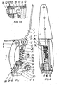
Figur 1 die Seitenansicht eines erfindungsgemäßen Kniegelenks,- Figur 1a einen.Schnitt entlang der Linie I - I,
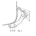
Figur 2 das Kniegelenk gemäßFigur 1 von vorn,- Figur 3 die Stellung der Lenker beim gebeugten Kniegelenk.
- FIG. 1 shows the side view of a knee joint according to the invention,
- Figure 1a shows a section along the line I - I,
- FIG. 2 the knee joint according to FIG. 1 from the front,
- Figure 3 shows the position of the handlebars with the knee flexed.
Das in den Figuren 1 bis 3 dargestellte Kniegelenk besteht aus einem Gelenkoberteil 1, das einstückig mit einem etwa L-förmig ausgebildeten Befestigungsanker 2 für einen Stumpfschaft 3 verbunden ist. Das Gelenkoberteil 1 ist mit einem Gelenkunterteil 4 über zwei Lenker 5, 6 verbunden. An dem Gelenkunterteil 4 wird das Unterschenkelrohr 7 einer Unterschenkelprothese befestigt.The knee joint shown in Figures 1 to 3 consists of an upper
Der in Gehrichtung gesehen vordere Lenker 5 ist an dem Gelenkoberteil 1 mit einem Gelenk 8 und an dem Gelenkunterteil 4 mit einem Drehgelenk 9 verbunden. Hinter diesen beiden Drehgelenken 8, 9 befinden sich zwei weitere Drehgelenke 10, 11, die durch den hinteren Lenker 6 verbunden sind.The
Die Lenker 5, 6 weisen beide die gleiche Form auf und stellen einen nach hinten gekrümmten Kreisbogenabschnitt dar. Sie sind aus einem Winkdurofil gebildet, das ihnen eine besondere Steifheit verleiht. Von vorn gesehen befinden sich die beiden Lenker auf verschiedenen Seiten der Kniegelenkmitte. Die Drehgelenke 8, 9, 10, 11 werden durch an den Lenkern 5, 6 befindliche Einsteckzapfen 12 gebildet, die mit 13 Passung in entsprechende Bohrungen in den Gelenkteilen 1, 4 eingesetzt sind.The
Die Drehgelenke 9, 11 in dem Gelenkunterteil 4 liegen horizontal nebeneinander, betrachtet bei einem senkrecht stehenden Unterschenkelrohr 7.The swivel joints 9, 11 in the lower
Die Verbindungslinie zwischen den beiden Drehgelenken 9, 11 steht senkrecht auf der Verbindungslinie zwischen den beiden hinteren Drehgelenken 10, 11. Die Verbindungslinie zwischen den beiden vorderen Drehgelenken 8, 9 bildet mit der Vertikalen einen kleinen Winkel « , ist also gegen die Verbindungslinie zwischen den beiden hinteren Drehgelenken 10, 11 um den Winkel geneigt. Daraus ergibt sich, daß der Abstand zwischen den beiden Drehgelenken 8, 10 im Gelenkoberteil 1 geringer ist, als der Abstand zwischen den beiden Drehgelenken 9, 11 im Gelenkunterteil 4. In dem dargestellten Ausführungsbeispiel beträgt der Abstand zwischen den oberen Drehgelenken 8, 10 ca. 2 cm, der Abstand zwischen den beiden unteren Drehgelenken 9, 11 ca. 4 cm und der Abstand zwischen den beiden hinteren Drehgelenken 10, 11 ca. 8 cm. Bei dieser Anordnung liegt der scheinbare Drehpunkt D des Kniegelenks anatomisch richtig innerhalb des Knies. Auch bei der Beugung des Kniegelenkes verändert er seine Lage nicht wesentlich. Das Kniegelenk bewirkt bei der Beugung eine anatomisch richtige Verkürzung des Beines, so daß eine genügende Freiheit für die Fußprothese vorhanden ist und der Prothesenträger ungehindert gehen kann.The connecting line between the two
Die Einsteckzapfen 12 sind als Hohlzapfen ausgeführt, in die Zapfen 14 eines Verriegelungselements 15 einsteckbar sind. Das Verriegelungselement 15 greift in die beiden Einsteckzapfen 12 im Gelenkunterteil 4 ein, und zwar mit einem kurzen Zapfen 14 in dem hinteren Drehgelenk 11 und in dem vorderen Drehgelenk 9 mit einem als Schraube 16 ausgebildeten Zapfen, der durch den Lenker 5 und den Einsteckzapfen 12 hindurchragend in das Verriegelungselement 15 eingeschraubt ist. Diese Schraube stellt das einzige Befestigungsmittel für alle Drehgelenke 8, 9, 10, 11 dar. Zugleich wird die Schraube 16 noch zur Verstellung der Achsfriktion ausgenutzt, in dem das Verriegelungselement 15 als Reibungsbremse ausgebildet ist. Es besteht nämlich an seinem die Schraube 16 aufnehmenden Ende aus einem Stapel von Kreisscheiben 17, die abwechselnd aus Metall und aus Kunststoff gebildet sind. Die Metallscheiben, mit Ausnahme derjenigen Metallscheibe, die mit der Federlasche 18 des Verriegelungselements 15, an der sich der kurze Zapfen 14 befindet, drehfest miteinander verbunden, während die Kunststoffscheiben frei drehbar sind. Die drehfeste Verbindung der Metallscheiben untereinander ist dadurch bewirkt, daß die äußerste Metallscheibe einen rechteckigen Ansatz aufweist, der in eine entsprechende Ausnehmung in dem DrehgeFhk 9 hineinpaßt. Eine entsprechende rechteckige Ausnehmung weisen die übrigen Metallscheiben auf. In dem rechteckigen Ansatz befindet sich auch das Gewinde für die Aufnahme der Schraube 16. Auf diese Weise wirkt jede Metallscheibe mit jeder Kunststoffscheibe als Reibfläche bei einer Drehung des Drehgelenks 9. Je nach der Stärke des Drucks durch die Schraube 16 ist die Reibung mehr oder weniger stark, so daß durch die Einstellung der Schraube 1.6 die Pendelbewegung des Unterschenkels reguliert werden kann.The insertion pins 12 are designed as hollow pins into which pins 14 of a locking
Zur Rückstellung des nach hinten abgeknickten Unterschenkels wird bei Kniegelenken ein Federelement 19 als sogenannteIn order to reset the lower leg bent backwards, a
Claims (19)
Priority Applications (1)
| Application Number | Priority Date | Filing Date | Title |
|---|---|---|---|
| AT79103542T ATE14976T1 (en) | 1978-09-27 | 1979-09-20 | ARTIFICIAL KNEE JOINT. |
Applications Claiming Priority (2)
| Application Number | Priority Date | Filing Date | Title |
|---|---|---|---|
| DE2841999A DE2841999C2 (en) | 1978-09-27 | 1978-09-27 | Artificial knee joint |
| DE2841999 | 1978-09-27 |
Publications (2)
| Publication Number | Publication Date |
|---|---|
| EP0010177A1 true EP0010177A1 (en) | 1980-04-30 |
| EP0010177B1 EP0010177B1 (en) | 1985-08-21 |
Family
ID=6050571
Family Applications (1)
| Application Number | Title | Priority Date | Filing Date |
|---|---|---|---|
| EP79103542A Expired EP0010177B1 (en) | 1978-09-27 | 1979-09-20 | Artificial knee joint |
Country Status (7)
| Country | Link |
|---|---|
| US (1) | US4310932A (en) |
| EP (1) | EP0010177B1 (en) |
| JP (1) | JPS55130657A (en) |
| AT (1) | ATE14976T1 (en) |
| CA (1) | CA1121104A (en) |
| DE (1) | DE2841999C2 (en) |
| ES (1) | ES245786Y (en) |
Cited By (3)
| Publication number | Priority date | Publication date | Assignee | Title |
|---|---|---|---|---|
| EP0243081A2 (en) * | 1986-04-16 | 1987-10-28 | J.E. HANGER & COMPANY LIMITED | Artificial knee with improved stable link-type knee joint |
| EP0439028A2 (en) | 1990-01-26 | 1991-07-31 | Otto Bock Orthopädische Industrie Besitz- und Verwaltungs-Kommanditgesellschaft | Swivelling connection between two parts of an orthopaedic device |
| WO2005104999A1 (en) * | 2004-04-30 | 2005-11-10 | medi Bayreuth Weihermüller & Voigtmann GmbH & Co. KG | Knee joint prosthesis |
Families Citing this family (47)
| Publication number | Priority date | Publication date | Assignee | Title |
|---|---|---|---|---|
| DE3414869C2 (en) * | 1984-04-19 | 1986-09-25 | Fa. Wilhelm Julius Teufel, 7000 Stuttgart | Artificial knee joint |
| GB2168106B (en) * | 1984-12-06 | 1987-10-14 | Weston Hydraulics Ltd | Joint for orthotic device |
| US4777941A (en) * | 1987-07-29 | 1988-10-18 | Borig Donald A | Orthopedic knee prosthesis and hinge |
| GB9023038D0 (en) * | 1990-10-23 | 1990-12-05 | Steeper Hugh Ltd | An orthopaedic or prosthetic joint |
| US5171325A (en) * | 1991-10-21 | 1992-12-15 | Aulie Alan L | Hinge structure for prosthetic joint |
| DE4137057A1 (en) * | 1991-11-11 | 1993-05-13 | Biedermann Motech Gmbh | ADJUSTABLE ORTHOSIS JOINT |
| DE4232602C2 (en) * | 1992-09-29 | 1995-01-12 | Bock Orthopaed Ind | Joint in orthopedic prostheses and orthoses |
| AU3505295A (en) * | 1994-09-09 | 1996-03-27 | University Of Toledo, The | Improved knee joint mechanism for knee disarticulation prosthesis |
| NL9401975A (en) * | 1994-11-25 | 1996-07-01 | P G Van De Veen Consultancy B | Device for pivotally connecting parts of an orthopedic device. |
| GB9605110D0 (en) * | 1996-03-11 | 1996-05-08 | Cooper John E | Knee mechanism for an artificial limb |
| US6113642A (en) | 1996-06-27 | 2000-09-05 | Mauch, Inc. | Computer controlled hydraulic resistance device for a prosthesis and other apparatus |
| JP3245828B2 (en) * | 1998-04-03 | 2002-01-15 | 株式会社ナブコ | Prosthesis with extension assist mechanism |
| US6306178B1 (en) * | 1998-10-22 | 2001-10-23 | Fountainhead | Prosthetic device using a cam-shaped wheel |
| US6610101B2 (en) | 2000-03-29 | 2003-08-26 | Massachusetts Institute Of Technology | Speed-adaptive and patient-adaptive prosthetic knee |
| US6752835B2 (en) * | 2002-04-16 | 2004-06-22 | Hsin Fa Shen | Tetraxial-link artificial limb joint |
| US7736394B2 (en) * | 2002-08-22 | 2010-06-15 | Victhom Human Bionics Inc. | Actuated prosthesis for amputees |
| EP1531766B1 (en) * | 2002-08-22 | 2012-08-01 | Victhom Human Bionics Inc. | Actuated leg prosthesis for above-knee amputees |
| US7198071B2 (en) * | 2003-05-02 | 2007-04-03 | Össur Engineering, Inc. | Systems and methods of loading fluid in a prosthetic knee |
| US7815689B2 (en) * | 2003-11-18 | 2010-10-19 | Victhom Human Bionics Inc. | Instrumented prosthetic foot |
| US20050107889A1 (en) | 2003-11-18 | 2005-05-19 | Stephane Bedard | Instrumented prosthetic foot |
| US7087090B2 (en) * | 2003-11-19 | 2006-08-08 | Bloorview Macmillan Centre | Artificial knee joint |
| US20060184280A1 (en) * | 2005-02-16 | 2006-08-17 | Magnus Oddsson | System and method of synchronizing mechatronic devices |
| JP5013881B2 (en) * | 2004-02-12 | 2012-08-29 | オサール ハゥーエッフ | System and method for motion controlled foot unit |
| US7896927B2 (en) | 2004-02-12 | 2011-03-01 | össur hf. | Systems and methods for actuating a prosthetic ankle based on a relaxed position |
| US20050283257A1 (en) * | 2004-03-10 | 2005-12-22 | Bisbee Charles R Iii | Control system and method for a prosthetic knee |
| CN1984623B (en) | 2004-03-10 | 2011-04-13 | 奥瑟Hf公司 | Control system and method for a prosthetic knee |
| US7691154B2 (en) * | 2004-05-07 | 2010-04-06 | össur hf | Systems and methods of controlling pressure within a prosthetic knee |
| EP1848380B1 (en) * | 2004-12-22 | 2015-04-15 | Össur hf | Systems and methods for processing limb motion |
| US8801802B2 (en) * | 2005-02-16 | 2014-08-12 | össur hf | System and method for data communication with a mechatronic device |
| SE528516C2 (en) | 2005-04-19 | 2006-12-05 | Lisa Gramnaes | Combined active and passive leg prosthesis system and a method for performing a movement cycle with such a system |
| US7485152B2 (en) * | 2005-08-26 | 2009-02-03 | The Ohio Willow Wood Company | Prosthetic leg having electronically controlled prosthetic knee with regenerative braking feature |
| EP1942843B1 (en) | 2005-09-01 | 2017-03-01 | Össur hf | System and method for determining terrain transitions |
| KR100630314B1 (en) * | 2005-11-09 | 2006-10-02 | 임규동 | A four-linkage orthosis joint |
| US10842653B2 (en) | 2007-09-19 | 2020-11-24 | Ability Dynamics, Llc | Vacuum system for a prosthetic foot |
| US8500824B2 (en) | 2008-03-07 | 2013-08-06 | Nabtesco Corporation | Knee joint including manual lock mechanism and artificial thigh |
| WO2009120637A1 (en) * | 2008-03-24 | 2009-10-01 | Ossur Hf | Transfemoral prosthetic systems and methods for operating the same |
| JP5709237B2 (en) | 2012-08-30 | 2015-04-30 | ナブテスコ株式会社 | Sealed prosthetic leg |
| WO2014133975A1 (en) | 2013-02-26 | 2014-09-04 | össur hf | Prosthetic foot with enhanced stability and elastic energy return |
| SE538280C2 (en) * | 2013-12-19 | 2016-04-26 | Fillauer Europ Ab | Orthopedic knee joint |
| US9687364B2 (en) * | 2014-09-25 | 2017-06-27 | Department Of Biotechnology, Ministry Of Science & Technology | Injection mouldable polymeric composite based passive polycentric knee joint |
| CA2969884C (en) * | 2014-12-08 | 2023-03-28 | Rehabilitation Institute Of Chicago | Powered and passive assistive device and related methods |
| JP6284878B2 (en) * | 2014-12-26 | 2018-02-28 | 本田技研工業株式会社 | Joint power control device |
| US11013620B2 (en) | 2015-06-26 | 2021-05-25 | Victoria Hand Project | Custom fitted body powered prosthetic upper limb manufactured by 3D printing |
| US10524950B2 (en) * | 2017-02-15 | 2020-01-07 | The Regents Of The University Of California | Modular semi-active joint exoskeleton |
| US11766350B2 (en) * | 2017-10-10 | 2023-09-26 | The Regents Of The University Of California | Method and apparatus for a passive knee joint |
| US11564815B2 (en) | 2019-09-17 | 2023-01-31 | Victoria Hand Project | Upper arm prosthetic apparatus and systems |
| US11957606B2 (en) | 2020-10-29 | 2024-04-16 | Victoria Hand Project | Low-cost prosthetic apparatus, methods, kits, and systems with improved force transfer elements |
Citations (8)
| Publication number | Priority date | Publication date | Assignee | Title |
|---|---|---|---|---|
| DE808743C (en) * | 1948-04-27 | 1951-07-19 | Heinrich Lammers | Artificial knee joint |
| FR1039077A (en) * | 1951-06-27 | 1953-10-05 | Knee joint enhancements for artificial leg | |
| DE1793820U (en) * | 1959-04-21 | 1959-08-20 | Paul Schlage | KNEE JOINT WITH ECCENTRIC FUNCTION. |
| DE1825882U (en) * | 1960-12-13 | 1961-02-02 | Fritz Krapinger | ARTIFICIAL KNEE JOINT. |
| GB1091015A (en) * | 1963-06-21 | 1967-11-15 | J E Hanger & Company Ltd | Improvements in joints for artificial limbs |
| GB1303738A (en) * | 1970-06-08 | 1973-01-17 | ||
| DE2432766A1 (en) * | 1973-08-24 | 1975-03-06 | Alfred Dr Menschik | Total knee-joint prosthesis - has parts forming linkage polygon to give motion resembling motion of natural knee throughout full range of bending |
| DE2332993B2 (en) * | 1973-06-28 | 1976-09-02 | J.E. Hanger And Co. Ltd., London | ARTIFICIAL LEG |
Family Cites Families (9)
| Publication number | Priority date | Publication date | Assignee | Title |
|---|---|---|---|---|
| US2208275A (en) * | 1937-06-25 | 1940-07-16 | French J Conner | Artificial knee |
| US2533008A (en) * | 1947-11-05 | 1950-12-05 | Gust Johnson | Artificial leg |
| GB897811A (en) * | 1959-10-09 | 1962-05-30 | Blatchford & Sons Ltd | Improvements in artificial legs |
| GB1247851A (en) * | 1968-06-26 | 1971-09-29 | Blatchford & Sons Ltd | Improvements in artificial legs |
| US3823424A (en) * | 1972-02-25 | 1974-07-16 | Hanger J And Co Ltd | Artificial leg with stable link-type knee joint |
| US4064569A (en) * | 1976-09-23 | 1977-12-27 | Campbell Harry E | Artificial polycentric knee joint |
| GB1536007A (en) * | 1976-12-15 | 1978-12-13 | Hanger & Co Ltd J E | Knee joints |
| US4152787A (en) * | 1977-07-11 | 1979-05-08 | Joseph Meggyesy | Prosthetic knee joint having weight responsive brake |
| GB1533796A (en) * | 1977-10-20 | 1978-11-29 | Blatchford & Sons Ltd C | Artificial leg |
-
1978
- 1978-09-27 DE DE2841999A patent/DE2841999C2/en not_active Expired
-
1979
- 1979-09-20 AT AT79103542T patent/ATE14976T1/en active
- 1979-09-20 EP EP79103542A patent/EP0010177B1/en not_active Expired
- 1979-09-26 US US06/078,934 patent/US4310932A/en not_active Expired - Lifetime
- 1979-09-26 ES ES1979245786U patent/ES245786Y/en not_active Expired
- 1979-09-27 JP JP12466479A patent/JPS55130657A/en active Granted
- 1979-09-27 CA CA000336507A patent/CA1121104A/en not_active Expired
Patent Citations (8)
| Publication number | Priority date | Publication date | Assignee | Title |
|---|---|---|---|---|
| DE808743C (en) * | 1948-04-27 | 1951-07-19 | Heinrich Lammers | Artificial knee joint |
| FR1039077A (en) * | 1951-06-27 | 1953-10-05 | Knee joint enhancements for artificial leg | |
| DE1793820U (en) * | 1959-04-21 | 1959-08-20 | Paul Schlage | KNEE JOINT WITH ECCENTRIC FUNCTION. |
| DE1825882U (en) * | 1960-12-13 | 1961-02-02 | Fritz Krapinger | ARTIFICIAL KNEE JOINT. |
| GB1091015A (en) * | 1963-06-21 | 1967-11-15 | J E Hanger & Company Ltd | Improvements in joints for artificial limbs |
| GB1303738A (en) * | 1970-06-08 | 1973-01-17 | ||
| DE2332993B2 (en) * | 1973-06-28 | 1976-09-02 | J.E. Hanger And Co. Ltd., London | ARTIFICIAL LEG |
| DE2432766A1 (en) * | 1973-08-24 | 1975-03-06 | Alfred Dr Menschik | Total knee-joint prosthesis - has parts forming linkage polygon to give motion resembling motion of natural knee throughout full range of bending |
Cited By (6)
| Publication number | Priority date | Publication date | Assignee | Title |
|---|---|---|---|---|
| EP0243081A2 (en) * | 1986-04-16 | 1987-10-28 | J.E. HANGER & COMPANY LIMITED | Artificial knee with improved stable link-type knee joint |
| EP0243081A3 (en) * | 1986-04-16 | 1990-04-25 | J.E. HANGER & COMPANY LIMITED | Artificial knee with improved stable link-type knee joint |
| EP0439028A2 (en) | 1990-01-26 | 1991-07-31 | Otto Bock Orthopädische Industrie Besitz- und Verwaltungs-Kommanditgesellschaft | Swivelling connection between two parts of an orthopaedic device |
| EP0439028A3 (en) * | 1990-01-26 | 1991-10-09 | Otto Bock Orthopaedische Industrie Besitz- Und Verwaltungs-Kommanditgesellschaft | Swivelling connection between two parts of an orthopaedic device |
| TR27847A (en) * | 1990-01-26 | 1995-09-01 | Bock Orthopaed Ind | Reversible liaison between two parts of an oropedic-technical auxiliary medium. |
| WO2005104999A1 (en) * | 2004-04-30 | 2005-11-10 | medi Bayreuth Weihermüller & Voigtmann GmbH & Co. KG | Knee joint prosthesis |
Also Published As
| Publication number | Publication date |
|---|---|
| EP0010177B1 (en) | 1985-08-21 |
| ATE14976T1 (en) | 1985-09-15 |
| US4310932A (en) | 1982-01-19 |
| CA1121104A (en) | 1982-04-06 |
| DE2841999A1 (en) | 1980-04-17 |
| JPS6144504B2 (en) | 1986-10-03 |
| ES245786Y (en) | 1980-07-01 |
| JPS55130657A (en) | 1980-10-09 |
| ES245786U (en) | 1980-01-16 |
| DE2841999C2 (en) | 1981-11-26 |
Similar Documents
| Publication | Publication Date | Title |
|---|---|---|
| EP0010177B1 (en) | Artificial knee joint | |
| DE2754422C2 (en) | Brake arrangement for a knee joint prosthesis | |
| DE2426070C3 (en) | Artificial ankle joint | |
| EP0529408B1 (en) | Knee endoprosthesis | |
| EP0672398B1 (en) | Swivelling connection between parts of an orthopaedic device | |
| DE2152639A1 (en) | Artificial skeletal joint | |
| EP0560141A1 (en) | Intervertebral disc endoprosthesis | |
| WO1995035524A1 (en) | Spectacle hinge | |
| DE2814111C2 (en) | ||
| DE69730865T2 (en) | KNEE MECHANISM FOR ARTIFICIAL LINK | |
| DE7141256U (en) | Joint - prosthesis | |
| DE2138153C3 (en) | Infinitely adjustable angle change unit with ball joint for adjusting orthosis and prosthesis parts in tubular frame construction | |
| DE4001199A1 (en) | Hinge for lid of box - has device to connect two parts of hinge without use of screws | |
| DE69104857T2 (en) | Ski binding. | |
| DE2856612A1 (en) | Safety spring back mirror mounting - has two sprung pivots with one joint locked when other is uncoupled | |
| DE2904776C2 (en) | ||
| DE60319855T2 (en) | ROTATABLE CONNECTION | |
| DE2742781A1 (en) | SWIVELING BRACKET, IN PARTICULAR FOR LAMPS AND THE like. | |
| EP0358633B1 (en) | Ski boot | |
| EP0040291B1 (en) | Prosthesis joint for knee and thigh amputees | |
| DE3124314C2 (en) | Overload safety device for plows | |
| DE2813169B1 (en) | Heald frame | |
| EP0639281B1 (en) | Flexural pivot for side-pieces of spectacles | |
| EP1292250B1 (en) | Knee-joint endoprosthesis | |
| DE19724577C1 (en) | Castor support wheel |
Legal Events
| Date | Code | Title | Description |
|---|---|---|---|
| PUAI | Public reference made under article 153(3) epc to a published international application that has entered the european phase |
Free format text: ORIGINAL CODE: 0009012 |
|
| AK | Designated contracting states |
Designated state(s): AT BE CH FR GB IT LU NL SE |
|
| 17P | Request for examination filed |
Effective date: 19801016 |
|
| ITF | It: translation for a ep patent filed | ||
| RAP1 | Party data changed (applicant data changed or rights of an application transferred) |
Owner name: OTTO BOCK ORTHOPAEDISCHE INDUSTRIE KG BESITZ- UND |
|
| GRAA | (expected) grant |
Free format text: ORIGINAL CODE: 0009210 |
|
| AK | Designated contracting states |
Designated state(s): AT BE CH FR GB IT LU NL SE |
|
| REF | Corresponds to: |
Ref document number: 14976 Country of ref document: AT Date of ref document: 19850915 Kind code of ref document: T |
|
| PG25 | Lapsed in a contracting state [announced via postgrant information from national office to epo] |
Ref country code: LU Free format text: LAPSE BECAUSE OF NON-PAYMENT OF DUE FEES Effective date: 19850930 |
|
| ET | Fr: translation filed | ||
| PLBE | No opposition filed within time limit |
Free format text: ORIGINAL CODE: 0009261 |
|
| STAA | Information on the status of an ep patent application or granted ep patent |
Free format text: STATUS: NO OPPOSITION FILED WITHIN TIME LIMIT |
|
| 26N | No opposition filed | ||
| ITTA | It: last paid annual fee | ||
| PGFP | Annual fee paid to national office [announced via postgrant information from national office to epo] |
Ref country code: AT Payment date: 19920930 Year of fee payment: 14 |
|
| PG25 | Lapsed in a contracting state [announced via postgrant information from national office to epo] |
Ref country code: AT Effective date: 19930920 |
|
| EAL | Se: european patent in force in sweden |
Ref document number: 79103542.1 |
|
| PGFP | Annual fee paid to national office [announced via postgrant information from national office to epo] |
Ref country code: SE Payment date: 19950811 Year of fee payment: 17 |
|
| PGFP | Annual fee paid to national office [announced via postgrant information from national office to epo] |
Ref country code: CH Payment date: 19950926 Year of fee payment: 17 Ref country code: BE Payment date: 19950926 Year of fee payment: 17 |
|
| PGFP | Annual fee paid to national office [announced via postgrant information from national office to epo] |
Ref country code: NL Payment date: 19950929 Year of fee payment: 17 |
|
| PG25 | Lapsed in a contracting state [announced via postgrant information from national office to epo] |
Ref country code: SE Effective date: 19960921 |
|
| PGFP | Annual fee paid to national office [announced via postgrant information from national office to epo] |
Ref country code: FR Payment date: 19960927 Year of fee payment: 18 |
|
| PG25 | Lapsed in a contracting state [announced via postgrant information from national office to epo] |
Ref country code: CH Effective date: 19960930 Ref country code: BE Effective date: 19960930 |
|
| BERE | Be: lapsed |
Owner name: OTTO BOCK ORTHOPADISCHE INDUSTRIE BESITZ- UND VER Effective date: 19960930 |
|
| PG25 | Lapsed in a contracting state [announced via postgrant information from national office to epo] |
Ref country code: NL Effective date: 19970401 |
|
| REG | Reference to a national code |
Ref country code: CH Ref legal event code: PL |
|
| NLV4 | Nl: lapsed or anulled due to non-payment of the annual fee |
Effective date: 19970401 |
|
| EUG | Se: european patent has lapsed |
Ref document number: 79103542.1 |
|
| PG25 | Lapsed in a contracting state [announced via postgrant information from national office to epo] |
Ref country code: FR Free format text: THE PATENT HAS BEEN ANNULLED BY A DECISION OF A NATIONAL AUTHORITY Effective date: 19970930 |
|
| REG | Reference to a national code |
Ref country code: FR Ref legal event code: ST |
|
| PGFP | Annual fee paid to national office [announced via postgrant information from national office to epo] |
Ref country code: GB Payment date: 19980914 Year of fee payment: 20 |
|
| PG25 | Lapsed in a contracting state [announced via postgrant information from national office to epo] |
Ref country code: GB Free format text: LAPSE BECAUSE OF NON-PAYMENT OF DUE FEES Effective date: 19990919 |
|
| REG | Reference to a national code |
Ref country code: GB Ref legal event code: PE20 Effective date: 19990919 |