EP0009606B1 - Dispositif de commande de charge d'une batterie d'accumulateurs - Google Patents
Dispositif de commande de charge d'une batterie d'accumulateurs Download PDFInfo
- Publication number
- EP0009606B1 EP0009606B1 EP79103112A EP79103112A EP0009606B1 EP 0009606 B1 EP0009606 B1 EP 0009606B1 EP 79103112 A EP79103112 A EP 79103112A EP 79103112 A EP79103112 A EP 79103112A EP 0009606 B1 EP0009606 B1 EP 0009606B1
- Authority
- EP
- European Patent Office
- Prior art keywords
- counter
- mains
- point
- data
- logic
- Prior art date
- Legal status (The legal status is an assumption and is not a legal conclusion. Google has not performed a legal analysis and makes no representation as to the accuracy of the status listed.)
- Expired
Links
Images
Classifications
-
- H—ELECTRICITY
- H02—GENERATION; CONVERSION OR DISTRIBUTION OF ELECTRIC POWER
- H02J—ELECTRIC POWER NETWORKS; CIRCUIT ARRANGEMENTS OR SYSTEMS FOR SUPPLYING OR DISTRIBUTING ELECTRIC POWER; SYSTEMS FOR STORING ELECTRIC ENERGY
- H02J7/00—Circuit arrangements for charging or discharging batteries or for supplying loads from batteries
- H02J7/90—Regulation of charging or discharging current or voltage
- H02J7/94—Regulation of charging or discharging current or voltage in response to battery current
-
- H—ELECTRICITY
- H02—GENERATION; CONVERSION OR DISTRIBUTION OF ELECTRIC POWER
- H02J—ELECTRIC POWER NETWORKS; CIRCUIT ARRANGEMENTS OR SYSTEMS FOR SUPPLYING OR DISTRIBUTING ELECTRIC POWER; SYSTEMS FOR STORING ELECTRIC ENERGY
- H02J9/00—Circuit arrangements for emergency or stand-by power supply, e.g. for emergency lighting
Definitions
- the present invention relates to a device for controlling the charging of a storage battery and more particularly to a device which allows the charging of a storage battery for a determined time and only when said battery has been discharged for a greater period. at minimum time.
- This invention applies in particular to the rapid charging of a backup battery which discharges in the absence of the mains. It is well known in this case to measure the discharge time of the battery or the discharged ampere-hours, and then to recharge the battery for a time dependent on the previous discharge, at a relatively rapid speed, then to switch to the speed d maintenance or completely cut the load as appropriate.
- the devices used for this are relatively sophisticated and expensive. In certain cases it is possible to be satisfied with giving a fast fixed charge, for example at constant voltage, and, to avoid too frequent overloads, to give this charge only when the previous discharge has exceeded a minimum time.
- Its object is a device for controlling the charging of a storage battery which discharges in the absence of the sector, comprises first means for detecting the absence of the sector, second means for comparing the time of absence of the sector at a first period, third means for measuring a second period during which the battery is recharged at a given speed and fourth means for acting on the second and third means as a function of the information given by the first means, characterized by the fact that the second means consist of a clock and a first counter, the third means consist of a second counter in series with the first, the fourth means consist of a first logic operator which receives first information given by the first means and a second information corresponding to the state of the second counter and consequently issues a third information prohibiting the operation of the clock when the sector is present and the second counter has reached a given state and allowing it in all other cases, by a means of transmitting said first information to the first counter, initializing it in the absence of the sector and in a second logical operator which receives the first information and a fourth information corresponding to
- the clock is started and the first counter is initialized, but the second counter is only initialized when the first counter arrives at a given state, the time it takes to reach this state corresponding to the minimum discharge time after which the battery is recharged at a relatively rapid speed, that is to say greater than the maintenance speed.
- the network returns the clock continues to run and the two counters fill up.
- the second counter has reached a given state which corresponds to the time of charging the battery at a fast speed, the information of this state, transmitted to the first operator, and combined with the information of the presence of the sector, brings l 'clock stop.
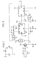
- FIG. 1 is shown separately the power supply of the device.
- This consists of the battery BA to be charged, the positive pole of which supplies a point P through a resistor R1 and the negative pole is connected to ground.
- the voltage supplied to the device via point P is stabilized by a Zener Z diode connected between this point and the negative pole of the battery.
- a point G is connected to the sector by a circuit CE which applies at this point a potential equal to that of the point P when the sector is present and the potential O when the latter is absent.
- the potential of point P represents the logic level 1 for the elements of the device which will be described and the ground potential represents the logic level 0.
- the point G is connected through a resistor R2 to the base of a pnp transistor T1 whose emitter is connected to the point P and the collector to ground through a resistor R3, as well as to a point A directly.
- Point A is connected to the inputs of a NAND gate 1 mounted as an inverter, the output B of which is connected to a first input of a NAND gate 2.
- the output C of this gate 2 is connected through a diode D1 on the one hand to the oscillating circuit of a clock comprising a capacitor C1 connected to the anode of diode D1 through a resistor R4 and on the other hand to an input CP1 of a counter IC1.
- the latter consists of an integrated circuit of C-MOS technique, sold by the company RCA under the reference CD 4060, this input being the terminal n ° 9 of this circuit.
- the point common to the anode of D1 and to the resistor R4 is connected to a point H'1 constituted by terminal n ° 11 of the counter IC1, and the point common to the capacitor C1 and to the resistor R4 is connected through a resistance R5 at a point H1, constituted by terminal 10 of this integrated circuit.
- the rest of the clock is made up of certain elements of the counter IC1, which has an initialization input constituted by its terminal No. 12 and referenced Rt1.
- This input is connected to a point D, which is connected on the one hand to the point A through a capacitor C2 and on the other hand to the ground through a resistor R6.
- the points A1 and A'1 are the power supply inputs of the counter IC1 and connected respectively to point P and to ground.
- An output Q14 of the counter IC1 (terminal n ° 3) transmits the clock pulses to an input CP2 (terminal n ° 1) of a counter IC2, constituted by an integrated circuit of technique C-MOS, which is sold by the RCA company under the reference CD 4024 and whose power supply inputs A2 and A'2 (terminals n ° 14 and 7) are connected respectively to point P and to earth.
- An output Q14 (terminal n ° 3) of the counter IC1 is connected through a capacitor C3 to a point E corresponding to an input of an AND gate 3. The point E is grounded through a resistor R7.
- the output F of gate 3 is connected to the input Rt2 (terminal no. 2) input for initializing the counter IC2.
- An output Q7 (terminal n ° 3) of the counter IC2 is connected on the one hand to a point H and on the other hand to the second input of door 2.
- the point H is connected to the battery charger (not shown) BA, and allows or prohibits fast charging according to its logic level.
- the counter IC2 has not changed state, the point H remains at level 1.
- the battery BA is not charging, because the H point must be at level 0 to allow the battery to be charged at a speed higher than the maintenance speed.
- the point E receives through the capacitor C3, a pulse at level 1.
- the point F briefly goes to level 1 and the input Rt 2 initializes the counter IC2 whose output Q7 goes to level 0, which allows the charger to switch to higher speed.
- the minimum discharge time is 5 minutes which are reached after 2 13 clock pulses.
- the IC2 counter is reset to 0 every 10 minutes during the absence of the sector.
- the charging time is 12 hours, or more exactly between 12 hours and 12 hours minus 10 minutes.
- the RCA integrated circuits CD 4060 and CD 4024 used in the device described can be replaced without other modifications by equivalent integrated circuits supplied by other manufacturers under references which also include the Nos. 4060 and 4024. Alternatively the functions of these Integrated circuits can be filled with other components subject to modifications of the connections if necessary.
Landscapes
- Engineering & Computer Science (AREA)
- Power Engineering (AREA)
- Business, Economics & Management (AREA)
- Emergency Management (AREA)
- Charge And Discharge Circuits For Batteries Or The Like (AREA)
Priority Applications (1)
| Application Number | Priority Date | Filing Date | Title |
|---|---|---|---|
| AT79103112T ATE627T1 (de) | 1978-08-30 | 1979-08-23 | Vorrichtung zum steuern der ladung einer batterie. |
Applications Claiming Priority (2)
| Application Number | Priority Date | Filing Date | Title |
|---|---|---|---|
| FR7824996 | 1978-08-30 | ||
| FR7824996A FR2435136A1 (fr) | 1978-08-30 | 1978-08-30 | Dispositif de commande de charge d'une batterie d'accumulateurs |
Publications (2)
| Publication Number | Publication Date |
|---|---|
| EP0009606A1 EP0009606A1 (fr) | 1980-04-16 |
| EP0009606B1 true EP0009606B1 (fr) | 1982-01-27 |
Family
ID=9212193
Family Applications (1)
| Application Number | Title | Priority Date | Filing Date |
|---|---|---|---|
| EP79103112A Expired EP0009606B1 (fr) | 1978-08-30 | 1979-08-23 | Dispositif de commande de charge d'une batterie d'accumulateurs |
Country Status (7)
| Country | Link |
|---|---|
| US (1) | US4286204A (enExample) |
| EP (1) | EP0009606B1 (enExample) |
| AT (1) | ATE627T1 (enExample) |
| CA (1) | CA1134431A (enExample) |
| DE (1) | DE2961978D1 (enExample) |
| FR (1) | FR2435136A1 (enExample) |
| ZA (1) | ZA794560B (enExample) |
Families Citing this family (7)
| Publication number | Priority date | Publication date | Assignee | Title |
|---|---|---|---|---|
| US4602203A (en) * | 1984-11-01 | 1986-07-22 | Med Care Of Kansas, Incorporated | Infrared battery detector and charging system |
| US4835453A (en) * | 1987-07-07 | 1989-05-30 | U.S. Philips Corp. | Battery-powered device |
| JPH04156233A (ja) * | 1990-10-19 | 1992-05-28 | Mitsubishi Electric Corp | 充電装置 |
| JPH07284233A (ja) * | 1994-04-05 | 1995-10-27 | Sony Corp | 充電方法及び充電装置 |
| US7205747B2 (en) * | 2004-07-09 | 2007-04-17 | Intersil Americas, Inc. | System and method for monitoring a charging period in a battery charger |
| US10931139B1 (en) | 2015-12-29 | 2021-02-23 | Signify Holding B.V. | Emergency battery packs for low voltage systems |
| US10424963B1 (en) * | 2016-02-18 | 2019-09-24 | Eaton Intelligent Power Limited | Methods and systems for charging a backup battery pack |
Family Cites Families (8)
| Publication number | Priority date | Publication date | Assignee | Title |
|---|---|---|---|---|
| DE1588286A1 (de) * | 1967-06-13 | 1970-09-17 | Herrmann Kg Fabrik Fuer Elektr | Zeitschalteinrichtung fuer Batterieladegeraete |
| FR1600361A (enExample) * | 1968-12-31 | 1970-07-20 | ||
| US3795818A (en) * | 1973-02-09 | 1974-03-05 | Shetec Inc | Emergency power supply |
| FR2237345A1 (en) * | 1973-06-28 | 1975-02-07 | Coredel | Automatic charging of lead acid batteries - is computer based and clock signals are compared with programme |
| GB1436819A (en) * | 1974-01-02 | 1976-05-26 | Lester Electrical Of Nebraska | Battery charger control circuit |
| CH596694A5 (enExample) * | 1974-06-26 | 1978-03-15 | Pro Casa Ges Reg Trust | |
| DE2438917C3 (de) * | 1974-08-09 | 1978-07-06 | Nife Stahlakkumulatoren Gmbh, 1000 Berlin | Einrichtung zum selbsttätigen Laden von Akkumulatoren-Batterien in Sicherheitsstromversorgungsanlagen |
| FR2361754A1 (fr) * | 1976-08-11 | 1978-03-10 | Accumulateurs Fixes | Procede et dispositif de controle de la charge et de la decharge d'une batterie d'accumulateurs |
-
1978
- 1978-08-30 FR FR7824996A patent/FR2435136A1/fr active Granted
-
1979
- 1979-08-14 US US06/066,384 patent/US4286204A/en not_active Expired - Lifetime
- 1979-08-23 AT AT79103112T patent/ATE627T1/de not_active IP Right Cessation
- 1979-08-23 EP EP79103112A patent/EP0009606B1/fr not_active Expired
- 1979-08-23 DE DE7979103112T patent/DE2961978D1/de not_active Expired
- 1979-08-27 CA CA000334641A patent/CA1134431A/fr not_active Expired
- 1979-08-29 ZA ZA00794560A patent/ZA794560B/xx unknown
Also Published As
| Publication number | Publication date |
|---|---|
| DE2961978D1 (en) | 1982-03-11 |
| FR2435136A1 (fr) | 1980-03-28 |
| ZA794560B (en) | 1980-08-27 |
| ATE627T1 (de) | 1982-02-15 |
| FR2435136B1 (enExample) | 1981-01-09 |
| EP0009606A1 (fr) | 1980-04-16 |
| CA1134431A (fr) | 1982-10-26 |
| US4286204A (en) | 1981-08-25 |
Similar Documents
| Publication | Publication Date | Title |
|---|---|---|
| EP0216662B1 (fr) | Dispositif de contrôle d'une batterie d'accumulateurs | |
| EP1079525B1 (fr) | Système de commande d'un interrupteur bidirectionnel à deux transistors | |
| EP0110775B1 (fr) | Régulateur à faible tension de déchet | |
| EP2354799B1 (fr) | Dispositif et procédé de comptage d'énergie électrique | |
| EP1854165B3 (fr) | Procede de chargement equilibre d'une batterie lithium-ion ou lithium polymere | |
| CA2224937A1 (fr) | Procede de regie pour ensemble accumulateur d'energie electrique et agencement de commande pour l'application de ce procede | |
| CA2692300C (fr) | Procede et systeme de gestion de coupures d'alimentation electrique a bord d'un aeronef | |
| EP2846394B1 (fr) | Batterie intelligente munie d'un circuit de gestion de la tension d'alimentation | |
| FR2584345A1 (fr) | Alimentation en energie electrique de circuits sur la roue pour un dispositif de surveillance des pneumatiques | |
| EP0991161A1 (fr) | Dispositif électronique portable avec circuit de contrôle de la décharge d'une batterie, et procédé associé | |
| EP0009606B1 (fr) | Dispositif de commande de charge d'une batterie d'accumulateurs | |
| EP1936541B1 (fr) | Chargeur de batterie fonctionnant par "tout ou rien" avec circuit de protection d'alimentation pour circuits intégrés monolithiques utilisant l'énergie de l'antenne | |
| EP3401647B1 (fr) | Système de mesure du niveau de puissance d'une source d'énergie ambiante | |
| EP1083645A1 (fr) | Déclencheur électronique comportant un dispositif d'initialisation | |
| EP3591475B1 (fr) | Montre thermoelectrique testable en production ou service apres-vente | |
| EP0080396B1 (fr) | Circuit téléphonique, géré par microprocesseur à circuit intégré de transmission 2 fils-4 fils, et alimentation de sauvegarde par courant de ligne | |
| FR2589292A1 (fr) | Procede et systeme de recharge de batterie d'accumulateurs, notamment pour batterie de secours d'une alimentation | |
| FR2751145A1 (fr) | Dispositif de controle de la charge d'un supercondensateur et procede de commande d'un tel dispositif | |
| FR2638585A1 (fr) | Chargeur pour accumulateur cadmium-nickel | |
| EP0899934A1 (fr) | Circuit adaptateur de tension d'alimentation | |
| FR3106447A1 (fr) | Element de stockage d’energie electrique et alimentation sauvegardee associee | |
| WO2026068476A1 (fr) | Systeme de gestion d'un pack batterie pour l'alimentation d'un actionneur en veille | |
| FR2474247A1 (fr) | Circuit de temporisation electronique a protection contre les interruptions d'alimentation | |
| EP0548725A1 (fr) | Dispositif d'évaluation de la tension fournie par une source de tension | |
| WO2002001696A1 (fr) | Dispositif d'alimentation d'un appareil electronique |
Legal Events
| Date | Code | Title | Description |
|---|---|---|---|
| PUAI | Public reference made under article 153(3) epc to a published international application that has entered the european phase |
Free format text: ORIGINAL CODE: 0009012 |
|
| AK | Designated contracting states |
Designated state(s): AT BE CH DE FR GB IT LU NL SE |
|
| 17P | Request for examination filed | ||
| ITF | It: translation for a ep patent filed | ||
| GRAA | (expected) grant |
Free format text: ORIGINAL CODE: 0009210 |
|
| AK | Designated contracting states |
Designated state(s): AT BE CH DE FR GB IT LU NL SE |
|
| REF | Corresponds to: |
Ref document number: 627 Country of ref document: AT Date of ref document: 19820215 Kind code of ref document: T |
|
| REF | Corresponds to: |
Ref document number: 2961978 Country of ref document: DE Date of ref document: 19820311 |
|
| PG25 | Lapsed in a contracting state [announced via postgrant information from national office to epo] |
Ref country code: LU Free format text: LAPSE BECAUSE OF NON-PAYMENT OF DUE FEES Effective date: 19820831 |
|
| PGFP | Annual fee paid to national office [announced via postgrant information from national office to epo] |
Ref country code: DE Payment date: 19830425 Year of fee payment: 5 Ref country code: CH Payment date: 19830425 Year of fee payment: 5 |
|
| PGFP | Annual fee paid to national office [announced via postgrant information from national office to epo] |
Ref country code: SE Payment date: 19830430 Year of fee payment: 5 |
|
| PGFP | Annual fee paid to national office [announced via postgrant information from national office to epo] |
Ref country code: LU Payment date: 19830518 Year of fee payment: 5 |
|
| PGFP | Annual fee paid to national office [announced via postgrant information from national office to epo] |
Ref country code: FR Payment date: 19830526 Year of fee payment: 5 |
|
| PGFP | Annual fee paid to national office [announced via postgrant information from national office to epo] |
Ref country code: BE Payment date: 19830630 Year of fee payment: 5 |
|
| PGFP | Annual fee paid to national office [announced via postgrant information from national office to epo] |
Ref country code: AT Payment date: 19830809 Year of fee payment: 5 |
|
| PGFP | Annual fee paid to national office [announced via postgrant information from national office to epo] |
Ref country code: NL Payment date: 19830831 Year of fee payment: 5 |
|
| PG25 | Lapsed in a contracting state [announced via postgrant information from national office to epo] |
Ref country code: AT Effective date: 19840823 |
|
| PG25 | Lapsed in a contracting state [announced via postgrant information from national office to epo] |
Ref country code: SE Effective date: 19840824 |
|
| PG25 | Lapsed in a contracting state [announced via postgrant information from national office to epo] |
Ref country code: CH Effective date: 19840831 |
|
| BERE | Be: lapsed |
Owner name: SAFT Effective date: 19840823 |
|
| PG25 | Lapsed in a contracting state [announced via postgrant information from national office to epo] |
Ref country code: NL Effective date: 19850301 |
|
| NLV4 | Nl: lapsed or anulled due to non-payment of the annual fee | ||
| PG25 | Lapsed in a contracting state [announced via postgrant information from national office to epo] |
Ref country code: FR Free format text: LAPSE BECAUSE OF NON-PAYMENT OF DUE FEES Effective date: 19850430 |
|
| REG | Reference to a national code |
Ref country code: CH Ref legal event code: PL |
|
| PG25 | Lapsed in a contracting state [announced via postgrant information from national office to epo] |
Ref country code: DE Effective date: 19850501 |
|
| GBPC | Gb: european patent ceased through non-payment of renewal fee | ||
| REG | Reference to a national code |
Ref country code: FR Ref legal event code: ST |
|
| PG25 | Lapsed in a contracting state [announced via postgrant information from national office to epo] |
Ref country code: GB Effective date: 19881118 |
|
| PG25 | Lapsed in a contracting state [announced via postgrant information from national office to epo] |
Ref country code: BE Effective date: 19890831 |
|
| EUG | Se: european patent has lapsed |
Ref document number: 79103112.3 Effective date: 19850612 |
|
| PLBE | No opposition filed within time limit |
Free format text: ORIGINAL CODE: 0009261 |
|
| STAA | Information on the status of an ep patent application or granted ep patent |
Free format text: STATUS: NO OPPOSITION FILED WITHIN TIME LIMIT |