EP0009543B1 - Humidificateur comportant des fibres creuses liées en faisceau - Google Patents
Humidificateur comportant des fibres creuses liées en faisceau Download PDFInfo
- Publication number
- EP0009543B1 EP0009543B1 EP79102287A EP79102287A EP0009543B1 EP 0009543 B1 EP0009543 B1 EP 0009543B1 EP 79102287 A EP79102287 A EP 79102287A EP 79102287 A EP79102287 A EP 79102287A EP 0009543 B1 EP0009543 B1 EP 0009543B1
- Authority
- EP
- European Patent Office
- Prior art keywords
- fibres
- humidifier
- water
- air
- pressure
- Prior art date
- Legal status (The legal status is an assumption and is not a legal conclusion. Google has not performed a legal analysis and makes no representation as to the accuracy of the status listed.)
- Expired
Links
- 239000012510 hollow fiber Substances 0.000 title description 6
- XLYOFNOQVPJJNP-UHFFFAOYSA-N water Substances O XLYOFNOQVPJJNP-UHFFFAOYSA-N 0.000 claims description 58
- 239000007788 liquid Substances 0.000 claims description 9
- PEDCQBHIVMGVHV-UHFFFAOYSA-N Glycerine Chemical group OCC(O)CO PEDCQBHIVMGVHV-UHFFFAOYSA-N 0.000 claims description 8
- 239000007789 gas Substances 0.000 claims description 7
- 239000000126 substance Substances 0.000 claims description 7
- 239000000080 wetting agent Substances 0.000 claims description 7
- 230000000241 respiratory effect Effects 0.000 claims description 6
- 229920002492 poly(sulfone) Polymers 0.000 claims description 5
- QVGXLLKOCUKJST-UHFFFAOYSA-N atomic oxygen Chemical compound [O] QVGXLLKOCUKJST-UHFFFAOYSA-N 0.000 claims description 4
- 230000005540 biological transmission Effects 0.000 claims description 4
- 235000011187 glycerol Nutrition 0.000 claims description 4
- 229910052760 oxygen Inorganic materials 0.000 claims description 4
- 239000001301 oxygen Substances 0.000 claims description 4
- 229920006243 acrylic copolymer Polymers 0.000 claims description 3
- CDOUZKKFHVEKRI-UHFFFAOYSA-N 3-bromo-n-[(prop-2-enoylamino)methyl]propanamide Chemical group BrCCC(=O)NCNC(=O)C=C CDOUZKKFHVEKRI-UHFFFAOYSA-N 0.000 claims description 2
- 235000019329 dioctyl sodium sulphosuccinate Nutrition 0.000 claims description 2
- 239000000835 fiber Substances 0.000 description 38
- 239000003570 air Substances 0.000 description 37
- 239000000463 material Substances 0.000 description 8
- 238000010276 construction Methods 0.000 description 5
- 238000009792 diffusion process Methods 0.000 description 4
- 238000004382 potting Methods 0.000 description 4
- 235000001674 Agaricus brunnescens Nutrition 0.000 description 3
- 239000012466 permeate Substances 0.000 description 3
- 230000029058 respiratory gaseous exchange Effects 0.000 description 3
- 239000004593 Epoxy Substances 0.000 description 2
- 230000001419 dependent effect Effects 0.000 description 2
- 238000004519 manufacturing process Methods 0.000 description 2
- 241000894006 Bacteria Species 0.000 description 1
- 239000004793 Polystyrene Substances 0.000 description 1
- 239000012080 ambient air Substances 0.000 description 1
- 230000036760 body temperature Effects 0.000 description 1
- 230000003247 decreasing effect Effects 0.000 description 1
- JMGZBMRVDHKMKB-UHFFFAOYSA-L disodium;2-sulfobutanedioate Chemical compound [Na+].[Na+].OS(=O)(=O)C(C([O-])=O)CC([O-])=O JMGZBMRVDHKMKB-UHFFFAOYSA-L 0.000 description 1
- 230000000694 effects Effects 0.000 description 1
- 239000008144 emollient laxative Substances 0.000 description 1
- 239000002657 fibrous material Substances 0.000 description 1
- 238000009472 formulation Methods 0.000 description 1
- 230000036449 good health Effects 0.000 description 1
- 229920005669 high impact polystyrene Polymers 0.000 description 1
- 239000004797 high-impact polystyrene Substances 0.000 description 1
- 230000002209 hydrophobic effect Effects 0.000 description 1
- 238000001746 injection moulding Methods 0.000 description 1
- 238000003780 insertion Methods 0.000 description 1
- 230000037431 insertion Effects 0.000 description 1
- 210000004072 lung Anatomy 0.000 description 1
- 230000013011 mating Effects 0.000 description 1
- 239000011159 matrix material Substances 0.000 description 1
- 239000012528 membrane Substances 0.000 description 1
- 238000000034 method Methods 0.000 description 1
- 239000000203 mixture Substances 0.000 description 1
- 239000004033 plastic Substances 0.000 description 1
- 229920002223 polystyrene Polymers 0.000 description 1
- 239000000523 sample Substances 0.000 description 1
- 229920002379 silicone rubber Polymers 0.000 description 1
- 239000004945 silicone rubber Substances 0.000 description 1
- APSBXTVYXVQYAB-UHFFFAOYSA-M sodium docusate Chemical group [Na+].CCCCC(CC)COC(=O)CC(S([O-])(=O)=O)C(=O)OCC(CC)CCCC APSBXTVYXVQYAB-UHFFFAOYSA-M 0.000 description 1
- 238000009987 spinning Methods 0.000 description 1
- 230000003068 static effect Effects 0.000 description 1
- 230000001954 sterilising effect Effects 0.000 description 1
- 238000004659 sterilization and disinfection Methods 0.000 description 1
Images


Classifications
-
- A—HUMAN NECESSITIES
- A61—MEDICAL OR VETERINARY SCIENCE; HYGIENE
- A61M—DEVICES FOR INTRODUCING MEDIA INTO, OR ONTO, THE BODY; DEVICES FOR TRANSDUCING BODY MEDIA OR FOR TAKING MEDIA FROM THE BODY; DEVICES FOR PRODUCING OR ENDING SLEEP OR STUPOR
- A61M16/00—Devices for influencing the respiratory system of patients by gas treatment, e.g. mouth-to-mouth respiration; Tracheal tubes
- A61M16/10—Preparation of respiratory gases or vapours
- A61M16/14—Preparation of respiratory gases or vapours by mixing different fluids, one of them being in a liquid phase
- A61M16/16—Devices to humidify the respiration air
-
- A—HUMAN NECESSITIES
- A61—MEDICAL OR VETERINARY SCIENCE; HYGIENE
- A61M—DEVICES FOR INTRODUCING MEDIA INTO, OR ONTO, THE BODY; DEVICES FOR TRANSDUCING BODY MEDIA OR FOR TAKING MEDIA FROM THE BODY; DEVICES FOR PRODUCING OR ENDING SLEEP OR STUPOR
- A61M16/00—Devices for influencing the respiratory system of patients by gas treatment, e.g. mouth-to-mouth respiration; Tracheal tubes
- A61M16/10—Preparation of respiratory gases or vapours
- A61M16/1075—Preparation of respiratory gases or vapours by influencing the temperature
- A61M16/1095—Preparation of respiratory gases or vapours by influencing the temperature in the connecting tubes
-
- A—HUMAN NECESSITIES
- A61—MEDICAL OR VETERINARY SCIENCE; HYGIENE
- A61M—DEVICES FOR INTRODUCING MEDIA INTO, OR ONTO, THE BODY; DEVICES FOR TRANSDUCING BODY MEDIA OR FOR TAKING MEDIA FROM THE BODY; DEVICES FOR PRODUCING OR ENDING SLEEP OR STUPOR
- A61M16/00—Devices for influencing the respiratory system of patients by gas treatment, e.g. mouth-to-mouth respiration; Tracheal tubes
- A61M16/10—Preparation of respiratory gases or vapours
- A61M16/14—Preparation of respiratory gases or vapours by mixing different fluids, one of them being in a liquid phase
- A61M16/142—Preparation of respiratory gases or vapours by mixing different fluids, one of them being in a liquid phase with semi-permeable walls separating the liquid from the respiratory gas
- A61M16/145—Preparation of respiratory gases or vapours by mixing different fluids, one of them being in a liquid phase with semi-permeable walls separating the liquid from the respiratory gas using hollow fibres
-
- B—PERFORMING OPERATIONS; TRANSPORTING
- B01—PHYSICAL OR CHEMICAL PROCESSES OR APPARATUS IN GENERAL
- B01D—SEPARATION
- B01D63/00—Apparatus in general for separation processes using semi-permeable membranes
- B01D63/02—Hollow fibre modules
-
- B—PERFORMING OPERATIONS; TRANSPORTING
- B01—PHYSICAL OR CHEMICAL PROCESSES OR APPARATUS IN GENERAL
- B01D—SEPARATION
- B01D63/00—Apparatus in general for separation processes using semi-permeable membranes
- B01D63/02—Hollow fibre modules
- B01D63/031—Two or more types of hollow fibres within one bundle or within one potting or tube-sheet
-
- A—HUMAN NECESSITIES
- A61—MEDICAL OR VETERINARY SCIENCE; HYGIENE
- A61M—DEVICES FOR INTRODUCING MEDIA INTO, OR ONTO, THE BODY; DEVICES FOR TRANSDUCING BODY MEDIA OR FOR TAKING MEDIA FROM THE BODY; DEVICES FOR PRODUCING OR ENDING SLEEP OR STUPOR
- A61M16/00—Devices for influencing the respiratory system of patients by gas treatment, e.g. mouth-to-mouth respiration; Tracheal tubes
- A61M16/08—Bellows; Connecting tubes ; Water traps; Patient circuits
- A61M16/0816—Joints or connectors
- A61M16/0833—T- or Y-type connectors, e.g. Y-piece
-
- Y—GENERAL TAGGING OF NEW TECHNOLOGICAL DEVELOPMENTS; GENERAL TAGGING OF CROSS-SECTIONAL TECHNOLOGIES SPANNING OVER SEVERAL SECTIONS OF THE IPC; TECHNICAL SUBJECTS COVERED BY FORMER USPC CROSS-REFERENCE ART COLLECTIONS [XRACs] AND DIGESTS
- Y10—TECHNICAL SUBJECTS COVERED BY FORMER USPC
- Y10S—TECHNICAL SUBJECTS COVERED BY FORMER USPC CROSS-REFERENCE ART COLLECTIONS [XRACs] AND DIGESTS
- Y10S261/00—Gas and liquid contact apparatus
- Y10S261/65—Vaporizers
Definitions
- This invention relates to a humidifier for humidifying and delivering gases such as air or oxygen directly to a patient or to a person in good health. It constitutes an improvement over my prior patents U.S. 3,616,796; 3,871,373; 3,912,795 and to later efforts of Dobritz, U.S. 4,010,748 and 4,086,305.
- a new type of medical humidifier which operates according to the diffusion principle in which water vapor from a water supply permeates a wall or membrane and enters a stream of breathing air while the water supply is maintained separate from the air stream by the wall.
- Such a diffusion humidifier offers a number of potential advantages over other methods of humidification, but no satisfactory form for its manufacture has been found.
- the humidifier is to be connected directly to the airway of a patient and life-supporting air is to be channeled through it, it should have low air-flow resistance, preferably so low that the patient can breath through the humidifier without assistance (e.g.
- DE-A-26 17 985 discloses a humidifier for a respiratory flow path but only with small bore fibres without incorporating of a wetting agent and does not give any teaching to expose the fibres to water under relatively negative pressure.
- DE-A-27 03 892 published after the claimed priority date, shows a humidifier for a respiratory flow path having an air-transmitting housing with a bundle of U-like hollow fibres through which the water streams. Such arrangement also could not fulfill required conditions for efficiency and safety.
- the humidifier for a respiratory flow path especially a medical humidifier, comprising a water chamber including a bundle of discrete elongated air-transmitting hollow fibres forming a compact nest and connected in parallel by inlet and outlet connections and having walls of a substance permeable to water vapor, whereby the water-filled chamber surrounds the effective length of the fibres is improved by the following features:
- the fibres are arranged to divide dry inhalation air (here the word "air” is intended to include pure or diluted oxygen) for a person or a patient into a series of air-flow filaments for humidification by water vapor that permeates walls of the fibres from the surrounding water under negative pressure.
- air dry inhalation air
- a humidifier is provided which can achieve full humidification of air in a practical, low-flow-resistance compact unit that can be disposable.
- said hollow fibres have a wall thickness that is 10% or less of the bore of said fibres.
- a further improvement may be achieved by an embodiment wherein the substance of the fibres has a transmission characteristic from 4,8 kg water per m 2 per hour of fibres wall area per 0,127 mm wall thickness, with water at 37.5°C, at 103 Torr negative pressure on the exterior of said fibres and with a flow of anhydrous oxygen at an aggregate rate of 200 litres per minute flowing in parallel through a bundle of fibres of 127 mm length.
- the fibres have advantageously an internal diameter of less than 1,78 mm (.070 inch).
- the substance of the fibres is selected from the group consisting of polysulfones and acrylic copolymers.
- the wetting agent is glycerine or dioctyl sodium sulfo succinate.
- an air flow resistance value R lies in the range of 52 and 134.
- L is the air-transmitting length and D the internal diameter of the fibres in cm, and N is the number of the fibres.
- Such humidifier could be improved by a number of fibres in the range of 100 to 200.
- the humidifier has an effective length of the fibres of 12,7 cm.
- the walls of said fibres are impermeable to liquid water under operating conditions and that said walls are 0.127 mm (0.005 inch) or less in thickness, the pressure of the air within the fibres is essentially atmospheric pressure and the pressure of the water on the exterior of the fibres is 137,3 mbar (-2 psig) negative pressure-In an improved embodiment of the invention, the nest of fibres has characteristic gas,pressure drop of 5 centimeters of water (5 mbar) across the length of the fibres when gas flows through the nest of fibres at the rate between 180 and 450 litres per minute.
- a humidifier constructed for the average adult could be improved in having an actual characteristic flow rate of 50 litres per minute or higher, and could be further improved in that the fibres define an aggregate water-vapor transmitting surface of 0.046 m 2 (one half square foot).
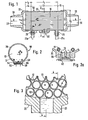
- the medical humidifier 50 comprises a bundle 10 of straight, elongated fibers, made of a substance (glycerinized polysulfone) which is permeable to water vapor and impermeable to liquid water under operating conditions.
- the fiber bundle is loosely arranged in its major mid-portion 12 to provide water flow passages 13 (Figs. 3 and 4) over the exterior of the fibers, while the end portions 14 and 16 of the bundle are potted (bonded together) in water-impermeable bonding material 18 (epoxy).
- the sides of the potted end portions 14, 16, are joined to end portions of chamber 20 defined by a rigid cylindrical wall (high density polystyrene). Between these ends the housing defines a water chamber capable of withstanding negative pressure.
- End caps 22 and 24 are provided at the respective ends of the housing, terminating in tapered external members 28. These serve as standard male breathing circuit connectors for insertion into mating female connectors or hose.
- the humidifier unit is connected in any suitable respiratory flow path.
- Fig. 5 the humidifier is shown in the inhalation leg from the respirator to a patient, with a respirator controlled exhalation valve 31 at the end of a Y connector exhausting to ambient.
- the end caps 22 and 24 each provide open spaces 30 and 32 beyond the ends of the fiber bundle, to define inlet and outlet air plenums.
- Air from the respirator 36 in Fig. 5 enters the male connector 28 at Fig. 1 at the right hand side, fills inlet air plenum 30 and is there distributed across the end face of the fiber bundle, where it splits, to enter the numerous hollow fibers as filaments of air flow. These proceed through the fibers under the pressure of the respirator, exiting into outlet air plenum 32 on the left hand side of Fig. 1 where they rejoin. The unified flow proceeds through the connector to the patient.
- the water chamber 20 has water inlet and outlet connectors 21, 23 (of different configuration to avoid mix-up) at the right and left hand sides of Fig. 1 respectively. These connectors and the conduits, 21 a, 23a are also of sufficiently rigid material to withstand negative pressure.
- Inlet conduit 21 a extends to a water reservoir 40 (Fig. 6) where the end is submerged in water.
- a heater element 42 maintains the water at the desired temperature under the control of probe 41 and thermostatic control switch 43.
- the water outlet conduit 23a is connected to the inlet of discharge pump P which discharges excess water into the reservoir 40. Water is drawn by the pump through the inlet 21 a and through the space between the loosely nested fibers, thus filling the entire free volume of chamber 20 with. water under negative pressure, e.g. 137.3 m bar (-2 psig). The water is drawn through discharge conduit 23a under the pull of discharge pump P.
- a positive pressure relief valve 60 (Fig. 2) is incorporated in the wall of the housing. As shown in Figs. 2 and 2a, this valve is of the so- called, well-known mushroom type.
- leaflet 62 overlying relief holes 64 which extend from the interior of the chamber 20 to the atmosphere.
- a stem 66 is integrally joined to leaflet 62 and ends in enlarged inward end 68 which is larger than the passage through which the stem 62 extends and therefore holds the leaflet in place.
- the leaflet seals the passages 64.
- this positive pressure acts through the passage 64 to deflect the leaflet 62 to allow escape of liquid until the positive pressure is relieved.
- the fibers have internal diameter of 1.52 mm (.060 inch) and wall thickness 0.127 mm (.005 in.). They are glycerinized to make them hydro- phyllic by being immersed in glycerine during spinning of the fibers, in a stage while the polysulfone is still soft.
- the fibers are 7.62 cm (3 inches) in length with 0.95 to 1.27 cm (3/8 to 1/2 inch) of each end sealed in the potting material, resulting in an effective vapor-transmitting length between the ends in the range of 5.08 and 5.72 cm (2 and 2-1/4 inch).
- 178 of the fibers are nested together and provide an aggregate vapor transmitting area in the range of 432 to 542 cm (67 to 84 in 2 ), depending upon the length of the potted end regions, and a capacity to humidify ambient air to saturation at 37°C (98.6°F) at air flow rates between about 85 and 95 liters/min.
- the flow resistance of this nested fiber module is represented by the figure of merit value where L is the air transmitting (overall) length of the fibers in cms., D is the internal diameter of the fibers in cm and N is the number of fibers. Using this module an air flow of 300 liters/min. is achievable with an air pressure drop of 5 cm H 2 0 from end to end of the hollow fibers.
- the humidifier can be placed in any of the variety of respirator circuits and flow paths and indeed the patient can spontaneously inhale through it with no assistance of a respirator.
- Suitable air flow characteristics in a practical, compact module are preferably achieved with fibers ranging in internal diameter upwards from 1.27 mm (.050 inch) to about 1.78 mm (.070 inch), the length of the fibers being dependent upon their diameter and upon the number N of the fibers to be employed. The number N is also dependent upon the specific vapor transmitting characteristic of the fiber material and wall thickness selected.
- the glycerinized fibers have the advantage of high vapor rate transmission and long dry shelf life and when used with the positive pressure relief valve, offer a fail-safe operation. Where even further safety is desired it is possible to use fibers which are more immune to transmission of liquid water even in the event of accidental application of positive pressure to the water chamber.
- the fibers are produced to the hardened stage as hydrophobic polysulfone dioctyl fibers and are subsequently treated with a wetting agent such as sodium sulfo succinate (stool softener marketed by Mead Johnson) and/or with glycerine.
- the valve is still preferred to maximize the safety of the device, particularly in view of the relatively larger number of fibers which are used when using material of the somewhat less vapor transmitting capability.
- the fibers are formed of acrylic co-polymers such as the XM formulation manufactured by Amicon Corporation.
- the water chamber 20 can advantageously be formed by injection molding of any suitable rigid plastic used in medical appliances, for instance the high impact polystyrene, mentioned above.
- the end caps, including the connectors, and defining the air plenums, can be of the same or similar material and can for instance be solvent-bonded to the exterior of the housing 20 in the manner shown.
- the assembly of fibers, having a length longer than the housing is inserted loosely in the housing, and the potting material, epoxy or others such as silicone rubber is introduced in the end regions, through capillary action along the fibers, sometimes assisted by centrifugal force.
- the extreme ends of the matrix of potting material and hollow fibers can be sliced, as with a knife, flush with the ends of the housing 20, to provide a smooth end face with the fiber ends open to transmit air.
- the resulting bundle of fibers can readily provide a diffusion wall surface area of the order of 0.046 m 2 (.5 square foot), effective to humidify an aggregate air flow volume of the order of 50 to 75 liters per minute at the instant of peak flow during the respirator cycle.
- the gross stream of inlet air A, Fig. 1, from the respirator 36 (Fig. 6) is divided into air stream filaments B,, B 2 , etc in Figs. 3 and 4 by the many fibers of the nest.
- the heated water, as indicated diagrammatically in Figs. 3 and 4 flows over the exterior of these fibers while water vapor produced by this water supply permeates the thin walls of the fibers, in opposition to the pressure differential, and humidifies the dry air filaments.
- the air stream filaments B l , B 2 , etc. after transmitting the length of the fibers 12 are humidified to saturation at. body temperature.
- the air filaments are then restored to a unified air flow C in the discharge plenum 32, which proceeds into the patient.
- the respirator 36 of Fig. 5 operates as an open cycle system in which exhaled air is discharged to the atmosphere through exhalation valve 31.
- the respirator gradually increases the pressure on conduit 54, supplying air through the humidifier 50 to the end of endotracheal tube 52 inserted into the airway of the patient.
- the valve 31 in the discharge leg 56 of the Y fitting is closed during this phase by a control line from the respirator, hence all air flow from the respirator is channeled through the humidifier 50 and into the patient.
- valve 31 is released by the control line from the respirator to relieve the exhaled air to the atmosphere.
- a check valve, not shown, during the expiration phase prevents back-flow of exhaled air through the humidifier.
- the hollow fibers being subjected to a decreasing pressure gradient from inside to outside take advantage of the substantial tensile strength of the wall of the fibers to ensure that they do not collapse. With the water under vacuum, little liquid water will enter the airway in the event of accidental rupture of a fiber wall. Even if a reverse pressure differential is encountered as by accidental misconnection of the pump, it is important to realize that the hollow fibers, due to their small size, demonstrate a sufficient degree of structural rigidity to resist crushing that would block the air flow to the patient.
- a sufficient vapor-transmitting surface area to volume ratio is obtained while still obtaining sufficient air-transmitting capacity to enable a small number of fibers, in the preferred range of 100 to 200, to be employed.
- the feature permits a large diffusion surface to be obtained in a small geometric volume.
- Such small size permits the humidifier to be mounted close to the patient, and permits it to be an inexpensive disposable component, to be replaced periodically, for instance once a day, at the same time that the hoses are ordinarily changed.
- the construction leads to the possibility of extending the time between sterilizations of the inlet hose, from the respirator to the humidifier, owing to the fact that it now does not contain moist warm air and therefore is not a place where bacteria multiply rapidly.
- a humidifier using static water at atmospheric pressure as by use of a collapsible outer wall can in certain instances be used to good effect with the specified fiber construction.
Claims (16)

Priority Applications (1)
| Application Number | Priority Date | Filing Date | Title |
|---|---|---|---|
| AT79102287T ATE1931T1 (de) | 1978-07-12 | 1979-07-05 | Anfeuchter mit gebuendelten hohlfasern. |
Applications Claiming Priority (4)
| Application Number | Priority Date | Filing Date | Title |
|---|---|---|---|
| US92390578A | 1978-07-12 | 1978-07-12 | |
| US923905 | 1978-07-12 | ||
| US4694379A | 1979-06-08 | 1979-06-08 | |
| US46943 | 1979-06-08 |
Publications (2)
| Publication Number | Publication Date |
|---|---|
| EP0009543A1 EP0009543A1 (fr) | 1980-04-16 |
| EP0009543B1 true EP0009543B1 (fr) | 1982-12-08 |
Family
ID=26724461
Family Applications (1)
| Application Number | Title | Priority Date | Filing Date |
|---|---|---|---|
| EP79102287A Expired EP0009543B1 (fr) | 1978-07-12 | 1979-07-05 | Humidificateur comportant des fibres creuses liées en faisceau |
Country Status (5)
| Country | Link |
|---|---|
| US (1) | US4381267A (fr) |
| EP (1) | EP0009543B1 (fr) |
| BR (1) | BR7904407A (fr) |
| CA (1) | CA1131524A (fr) |
| DE (1) | DE2964203D1 (fr) |
Cited By (1)
| Publication number | Priority date | Publication date | Assignee | Title |
|---|---|---|---|---|
| US6394084B1 (en) | 1996-07-16 | 2002-05-28 | Respironics, Inc. | Humidification unit, method of making same, and ventilatory system using such a humidification unit |
Families Citing this family (85)
| Publication number | Priority date | Publication date | Assignee | Title |
|---|---|---|---|---|
| JPS57209603A (en) * | 1981-06-26 | 1982-12-23 | Nikoraebitsuchi Chi Reonitsudo | Membrane element and apparatus for separating mixture of gas and liquid phases |
| FR2564733B1 (fr) * | 1984-05-22 | 1987-05-29 | Centre Nat Rech Scient | Appareil portable de lutte contre l'hypothermie chez l'homme, par inhalation d'air chaud et humidifie |
| US4773410A (en) * | 1984-10-09 | 1988-09-27 | Transpirator Technologies, Inc. | Method and apparatus for the treatment of the respiratory track with vapor-phase water |
| JPS62501265A (ja) * | 1984-10-09 | 1987-05-21 | オキシジン インリツチメント カンパニ− リミテツド | 気道治療のための方法および装置 |
| AU581986B2 (en) * | 1985-05-22 | 1989-03-09 | Fisher & Paykel Healthcare Limited | Improvements in or relating to methods of and/or apparatus for humidifying gases |
| JPS61280871A (ja) * | 1985-06-06 | 1986-12-11 | テルモ株式会社 | 呼吸用加温加湿器 |
| US4953546A (en) * | 1985-07-16 | 1990-09-04 | Transpirator Technologies, Inc. | Method and apparatus for pulmonary and cariovascular conditioning of the young of large animals |
| US4955372A (en) * | 1985-07-16 | 1990-09-11 | Transpirator Technologies, Inc. | Method and apparatus for pulmonary and cardiovascular conditioning of racehorses and competition animals |
| US4859331A (en) * | 1987-05-19 | 1989-08-22 | Dragerwerk Aktiengesellschaft | System for exchanging a substance between fluids |
| DE3716653A1 (de) * | 1987-05-19 | 1988-12-08 | Draegerwerk Ag | Stoffaustauschsystem, insbesondere zur befeuchtung von gasen |
| US4861523A (en) * | 1987-07-13 | 1989-08-29 | Beran Anthony V | Humidification in respiratory systems |
| US5172686A (en) * | 1987-08-20 | 1992-12-22 | Anthony Jean M | Device for supplying air or medical gases in a conditioned, particularly a moistented and/or heated state to a patient |
| DE3819988A1 (de) * | 1988-06-11 | 1989-12-14 | Draegerwerk Ag | Atemluftanfeuchter fuer ein atemschutzgeraet |
| US4910384A (en) * | 1988-08-23 | 1990-03-20 | The Kendall Company | Position independent humidifier apparatus |
| EP0519132A1 (fr) * | 1989-10-18 | 1992-12-23 | Exxon Research And Engineering Company | Module à fibres creuses |
| JP2688662B2 (ja) * | 1991-07-05 | 1997-12-10 | ジャパンゴアテックス株式会社 | 加湿器における加湿水流路 |
| SE502103C2 (sv) * | 1991-08-01 | 1995-08-14 | Gambro Dialysatoren | Filterenhet för överföring av massa och/eller värme innehållande hålrumsfibrer |
| US5368786A (en) * | 1992-09-30 | 1994-11-29 | Wisconsin Alumni Research Foundation | Apparatus and methods for humidity control |
| US5348691A (en) * | 1993-06-11 | 1994-09-20 | United Technologies Corporation | Atmosphere membrane humidifier and method and system for producing humidified air |
| US5996976A (en) * | 1993-07-13 | 1999-12-07 | Lynntech, Inc. | Gas humidification system using water permeable membranes |
| SE9303044L (sv) * | 1993-09-17 | 1994-10-24 | Gibeck Respiration Ab | Anordning vid fukt-värmeväxlare |
| CA2163955A1 (fr) * | 1995-03-09 | 1996-09-10 | Nicholas F. Didomenico | Dispositif servant a l'humidification |
| JPH08266631A (ja) * | 1995-03-31 | 1996-10-15 | Asahi Glass Co Ltd | 呼吸用気体の加湿装置 |
| GB9514527D0 (en) * | 1995-07-15 | 1995-09-13 | Smiths Industries Plc | Heat and moisture exchangers |
| DE19621541C1 (de) * | 1996-05-29 | 1997-04-10 | Draegerwerk Ag | Beatmungsanfeuchter |
| JP3748466B2 (ja) | 1996-08-23 | 2006-02-22 | 株式会社メトラン | 加湿調整ユニット及び加湿調整ユニットの製造方法 |
| CA2222830C (fr) * | 1996-12-02 | 2004-03-30 | Fisher & Paykel Limited | Appareil de traitement d'apnee obstructive du sommeil |
| US6510848B1 (en) * | 1998-04-22 | 2003-01-28 | Mallinckrodt, Inc. | Disposable active humidifier for the mechanical ventilation of a patient |
| ITMI980862A1 (it) * | 1998-04-22 | 1999-10-22 | Mallinckrodt Holding Bv | Umidificatore attivo monouso per la ventilazione meccanica di un paziente |
| ES2251416T3 (es) * | 1999-12-10 | 2006-05-01 | Vapotherm, Inc. | Aparato para terapia del tracto respiratorio. |
| EP1586345A1 (fr) * | 1999-12-10 | 2005-10-19 | Vapotherm, Inc. | Appareil et méthode pour la thérapie des voies aériennes |
| US6976489B2 (en) | 2000-06-30 | 2005-12-20 | Northgate Technologies, Inc. | Method and apparatus for humidification and warming of air |
| US7708013B2 (en) * | 2000-12-08 | 2010-05-04 | Vapotherm, Inc. | Apparatus and method for delivering water vapor to a gas |
| WO2002085417A2 (fr) * | 2001-04-24 | 2002-10-31 | Medi-Physics, Inc. | Procedes et dispositifs d'humidification de gaz rares hyperpolarises et produits de gaz hyperpolarises inhalables pharmaceutiques humidifies associes |
| JP2003111774A (ja) * | 2001-07-31 | 2003-04-15 | Senko Medical Instr Mfg Co Ltd | 気腹ガス用加温加湿器及び気腹装置 |
| US6557266B2 (en) * | 2001-09-17 | 2003-05-06 | John Griffin | Conditioning apparatus |
| US7827981B2 (en) | 2003-01-29 | 2010-11-09 | Vapotherm, Inc. | Method for reducing the work of breathing |
| US20040211421A1 (en) * | 2003-02-20 | 2004-10-28 | Bird Products Corporation, A California Corporation | Air-to-air heat exchange for medical ventilator |
| US7476212B2 (en) * | 2003-06-12 | 2009-01-13 | Michael Spearman | Medical gas humidification system |
| FR2856939B1 (fr) * | 2003-07-03 | 2005-09-30 | Jobin Yvon Sas | Humidificateur de gaz |
| US20060285091A1 (en) * | 2003-07-21 | 2006-12-21 | Parekh Bipin S | Lithographic projection apparatus, gas purging method, device manufacturing method and purge gas supply system related application |
| US7384149B2 (en) * | 2003-07-21 | 2008-06-10 | Asml Netherlands B.V. | Lithographic projection apparatus, gas purging method and device manufacturing method and purge gas supply system |
| WO2005056092A1 (fr) * | 2003-12-15 | 2005-06-23 | Teijin Pharma Limited | Dispositif d'humidification et systeme de concentration d'oxygene |
| US20060081247A1 (en) * | 2004-10-20 | 2006-04-20 | Danny Britt | Humidifier for breathing apparatus and method of humidifying a breathing apparatus gas strem |
| JP4771711B2 (ja) * | 2005-02-15 | 2011-09-14 | 株式会社メトラン | 呼吸回路用の加湿装置 |
| ATE412148T1 (de) * | 2005-03-29 | 2008-11-15 | Moeritz Martin Dr Ing | Vorrichtung und verfahren zur befeuchtung eines luftstromes |
| EP2012858A2 (fr) | 2006-04-10 | 2009-01-14 | Aeiomed, INC. | Appareil et méthodes pour administrer des thérapies en pression positive aux voies aeriennes |
| US8074645B2 (en) * | 2006-04-10 | 2011-12-13 | Somnetics Global Pte. Ltd. | Apparatus and methods for providing humidity in respiratory therapy |
| US8211052B1 (en) | 2006-07-13 | 2012-07-03 | Lexion Medical Llc | Charged hydrator |
| JP2008057947A (ja) * | 2006-08-31 | 2008-03-13 | Satako:Kk | 気体加湿装置 |
| US20080078397A1 (en) * | 2006-09-28 | 2008-04-03 | Ronald Scott | Hose support system |
| US7866637B2 (en) * | 2007-01-26 | 2011-01-11 | Asml Netherlands B.V. | Humidifying apparatus, lithographic apparatus and humidifying method |
| US20080217795A1 (en) * | 2007-03-07 | 2008-09-11 | Alexander Gofer | Humidifier device for fuel cell |
| US8079574B2 (en) | 2007-05-16 | 2011-12-20 | ZenPure Corp. | Membrane based contactor module for mass and heat transfer |
| US8236081B2 (en) * | 2007-07-17 | 2012-08-07 | Teleflex Medical Incorporated | Permeable membrane water dissipation device |
| EP3871722A1 (fr) | 2007-07-18 | 2021-09-01 | Vapotherm, Inc. | Système d'administration de gaz réchauffé et humidifié |
| US8905023B2 (en) | 2007-10-05 | 2014-12-09 | Vapotherm, Inc. | Hyperthermic humidification system |
| US8517017B2 (en) * | 2009-01-08 | 2013-08-27 | Hancock Medical, Inc. | Self-contained, intermittent positive airway pressure systems and methods for treating sleep apnea, snoring, and other respiratory disorders |
| US20120031405A1 (en) * | 2010-06-07 | 2012-02-09 | Cva Technologies, Llc | Methods and systems for cerebral cooling |
| US9032951B2 (en) * | 2010-08-24 | 2015-05-19 | Trudell Medical International | Aerosol delivery device |
| US8327846B2 (en) | 2011-02-08 | 2012-12-11 | Hancock Medical, Inc. | Positive airway pressure system with head position control |
| US9375546B2 (en) | 2012-06-26 | 2016-06-28 | William Henry Ruff | Personal airway humidification and oxygen-enrichment apparatus and method |
| US9289573B2 (en) | 2012-12-28 | 2016-03-22 | Covidien Lp | Ventilator pressure oscillation filter |
| US10314989B2 (en) | 2013-01-28 | 2019-06-11 | Hancock Medical, Inc. | Position control devices and methods for use with positive airway pressure systems |
| US20150165146A1 (en) | 2013-12-17 | 2015-06-18 | Bruce Bowman | Humidification system and positive airway pressure apparatus incorporating same |
| US10344753B2 (en) | 2014-02-28 | 2019-07-09 | Encite Llc | Micro pump systems |
| US10881829B2 (en) | 2014-08-18 | 2021-01-05 | Resmed Inc. | Portable pap device with humidification |
| US10596345B2 (en) * | 2014-12-31 | 2020-03-24 | Vapotherm, Inc. | Systems and methods for humidity control |
| US10247432B1 (en) * | 2015-02-06 | 2019-04-02 | Elemental Scientific, Inc. | System for humidifying gas streams |
| USD776802S1 (en) | 2015-03-06 | 2017-01-17 | Hancock Medical, Inc. | Positive airway pressure system console |
| US10398871B2 (en) * | 2015-03-31 | 2019-09-03 | Vapotherm, Inc. | Systems and methods for patient-proximate vapor transfer for respiratory therapy |
| US11471636B2 (en) | 2015-04-15 | 2022-10-18 | Medline Industries, Lp | Moisture removal and condensation and humidity management apparatus for a breathing circuit |
| WO2017040486A1 (fr) * | 2015-08-31 | 2017-03-09 | Vapotherm, Inc. | Thérapie à haute fluidité avec concentrateur d'oxygène intégré |
| US11247007B2 (en) * | 2015-10-16 | 2022-02-15 | Metran Co., Ltd. | Silencer and artificial ventilator |
| US20170143930A1 (en) * | 2015-11-19 | 2017-05-25 | Cray V. Noah | Method and apparatus for maintaining patient body temperature during surgery |
| US20170182280A1 (en) * | 2015-12-29 | 2017-06-29 | Vapotherm, Inc. | Axial flow vapor transfer cartridge with large diameter fibers |
| CN109310348B (zh) | 2016-05-19 | 2022-01-25 | 汉考克医药公司 | 姿势阻塞性睡眠呼吸暂停检测系统 |
| AU2017341838A1 (en) | 2016-10-14 | 2019-05-02 | Vapotherm, Inc. | Systems and methods for high velocity nasal insufflation |
| EP3528880B1 (fr) | 2016-10-19 | 2021-07-07 | Teleflex Medical Incorporated | Appareil d'élimination d'humidité et de gestion de condensation et d'humidité pour un circuit respiratoire |
| CN106390255A (zh) * | 2016-10-20 | 2017-02-15 | 王冕 | 一种一次性湿化鼻氧管 |
| US10960165B2 (en) | 2017-07-10 | 2021-03-30 | Teleflex Medical Incorporated | Moisture removal and condensation and humidity management apparatus for a breathing circuit |
| AU2019205813B2 (en) | 2018-01-08 | 2021-06-24 | Vivonics, Inc. | System and method for cooling the brain of a human subject |
| US11247017B2 (en) * | 2018-11-20 | 2022-02-15 | Pegasus Research Corporation | Capsule humidifier |
| CN113082419B (zh) * | 2021-04-19 | 2022-12-30 | 四川大学华西医院 | 吸氧装置 |
| CN115990307B (zh) * | 2023-03-17 | 2023-06-13 | 北京神鹿医疗器械有限公司 | 一种具有加湿功能的制氧机 |
Family Cites Families (24)
| Publication number | Priority date | Publication date | Assignee | Title |
|---|---|---|---|---|
| BE608328A (fr) * | 1960-09-19 | |||
| US3186941A (en) * | 1962-08-02 | 1965-06-01 | Dow Chemical Co | Water softening with fine cation exchange tubes |
| US3277959A (en) * | 1964-08-12 | 1966-10-11 | Du Pont | Plastic tube heat exchanger and process of making |
| US3342729A (en) * | 1964-12-09 | 1967-09-19 | Dow Chemical Co | Permeability separatory cell and apparatus and method of using the same |
| NL151792C (fr) * | 1965-01-14 | |||
| US3423481A (en) * | 1965-02-09 | 1969-01-21 | Tokuyama Soda Kk | Difficultly dyeable polymers containing copolymers of ethylenically unsaturated monomers containing glycidyl groups |
| US3228456A (en) * | 1965-03-01 | 1966-01-11 | Du Pont | Method and apparatus employing hollow polyfluorinated plastic filaments for heat exchange |
| US3339341A (en) * | 1965-12-22 | 1967-09-05 | Du Pont | Fluid separation process and apparatus |
| US3373876A (en) * | 1966-05-12 | 1968-03-19 | Dow Chemical Co | Artificial body organ apparatus |
| CA1054073A (fr) * | 1968-12-26 | 1979-05-08 | Nat Shaye | Element filtrant de fluides a purge de gaz |
| US3616796A (en) * | 1969-06-30 | 1971-11-02 | Richard Robert Jackson | Humidified respiratory tube and method |
| US3772072A (en) * | 1971-06-14 | 1973-11-13 | Eastman Kodak Co | Method for treating reverse osmosis membranes |
| US3803810A (en) * | 1972-05-01 | 1974-04-16 | Pall Corp | Liquid-gas separator and filter |
| US4098852A (en) * | 1972-07-04 | 1978-07-04 | Rhone-Poulenc, S.A. | Process for carring out a gas/liquid heat-exchange |
| US3871373A (en) * | 1972-10-30 | 1975-03-18 | Richard R Jackson | Humidifying gas |
| US3912795A (en) * | 1972-10-30 | 1975-10-14 | Richard R Jackson | Humidifying gas |
| US3905905A (en) * | 1974-01-11 | 1975-09-16 | Ivac Corp | Filter unit |
| FR2267138A1 (en) * | 1974-04-09 | 1975-11-07 | Rhone Poulenc Ind | Hollow fibre bundle for fluid treatment - partic. useful for dialysis or ultrafiltration |
| CH581474A5 (fr) * | 1974-06-27 | 1976-11-15 | Draegerwerk Ag | |
| DE2554062C3 (de) * | 1974-12-04 | 1980-12-18 | Asahi Kasei Kogyo K.K., Osaka (Japan) | Dialyseneinheiten |
| US4031012A (en) * | 1975-09-17 | 1977-06-21 | Gics Pharmaceuticals, Inc. | Separatory apparatus |
| DE2617985C3 (de) * | 1976-04-24 | 1979-02-22 | Draegerwerk Ag, 2400 Luebeck | Atemluftanfeuchter für Beatmungsvorrichtungen |
| US4086305A (en) * | 1976-06-10 | 1978-04-25 | Dragerwerk Aktiengesellschaft | Humidifier for respirators having a sealed container water supply to a water storage tank |
| DE2703892C2 (de) * | 1977-01-31 | 1982-09-23 | Drägerwerk AG, 2400 Lübeck | Atemluftanfeuchter für Beatmungsvorrichtungen |
-
1979
- 1979-07-05 DE DE7979102287T patent/DE2964203D1/de not_active Expired
- 1979-07-05 EP EP79102287A patent/EP0009543B1/fr not_active Expired
- 1979-07-11 CA CA331,617A patent/CA1131524A/fr not_active Expired
- 1979-07-11 BR BR7904407A patent/BR7904407A/pt unknown
-
1981
- 1981-05-28 US US06/267,867 patent/US4381267A/en not_active Expired - Lifetime
Cited By (2)
| Publication number | Priority date | Publication date | Assignee | Title |
|---|---|---|---|---|
| US6394084B1 (en) | 1996-07-16 | 2002-05-28 | Respironics, Inc. | Humidification unit, method of making same, and ventilatory system using such a humidification unit |
| US6557551B2 (en) | 1996-07-16 | 2003-05-06 | Respironics, Inc. | Unit for adjusting humidification |
Also Published As
| Publication number | Publication date |
|---|---|
| DE2964203D1 (en) | 1983-01-13 |
| US4381267A (en) | 1983-04-26 |
| EP0009543A1 (fr) | 1980-04-16 |
| CA1131524A (fr) | 1982-09-14 |
| BR7904407A (pt) | 1980-06-24 |
Similar Documents
| Publication | Publication Date | Title |
|---|---|---|
| EP0009543B1 (fr) | Humidificateur comportant des fibres creuses liées en faisceau | |
| US6367472B1 (en) | Respiration humidifier | |
| US3912795A (en) | Humidifying gas | |
| US3901230A (en) | Anesthesia rebreathing apparatus including improved reservoir means | |
| EP0176651B1 (fr) | Echangeur de chaleur avec oxygénation pour le sang | |
| CA1319678C (fr) | Echangeur de chaleur portatif pour rechauffement par inhalation | |
| DK168811B1 (da) | Vejrtrækningskredsløb | |
| US3616796A (en) | Humidified respiratory tube and method | |
| US3881482A (en) | Device for moistening and heating inhalation air with tracheotomy and endotracheal intubation | |
| EP0397446A2 (fr) | Humidification dans les systèmes respiratoires | |
| US3892533A (en) | Oxygenator gas distribution header | |
| JPH0252510B2 (fr) | ||
| EP1083954B1 (fr) | Ensemble humidificateur | |
| WO2006044927A1 (fr) | Humidificateur pour appareil respiratoire et procede permettant d'humidifier un courant gazeux d'un appareil respiratoire | |
| US6723132B2 (en) | Artificial lung device | |
| US3102537A (en) | Respiratory apparatus | |
| JPH10511578A (ja) | 加熱可能な呼吸系治療用給湿器 | |
| JP5097779B2 (ja) | 医療用ガスの加湿器、医療用ガスの加湿・搬送システムおよび人工呼吸器システム | |
| JPS62501265A (ja) | 気道治療のための方法および装置 | |
| US5120502A (en) | Pressure relief valve for membrane oxygenator | |
| JPS6253193B2 (fr) | ||
| JP3650647B2 (ja) | 気体加湿器 | |
| JP2006116258A (ja) | 加温加湿容器 | |
| US20220347414A1 (en) | Dual-pressure respiratory assistance device | |
| CN204864462U (zh) | 一种气切型热湿交换器 |
Legal Events
| Date | Code | Title | Description |
|---|---|---|---|
| PUAI | Public reference made under article 153(3) epc to a published international application that has entered the european phase |
Free format text: ORIGINAL CODE: 0009012 |
|
| AK | Designated contracting states |
Designated state(s): AT CH DE FR GB IT NL SE |
|
| 17P | Request for examination filed | ||
| ITF | It: translation for a ep patent filed |
Owner name: UFFICIO TECNICO ING. A. MANNUCCI |
|
| GRAA | (expected) grant |
Free format text: ORIGINAL CODE: 0009210 |
|
| AK | Designated contracting states |
Designated state(s): AT CH DE FR GB IT NL SE |
|
| REF | Corresponds to: |
Ref document number: 1931 Country of ref document: AT Date of ref document: 19821215 Kind code of ref document: T |
|
| REF | Corresponds to: |
Ref document number: 2964203 Country of ref document: DE Date of ref document: 19830113 |
|
| ET | Fr: translation filed | ||
| ITTA | It: last paid annual fee | ||
| EAL | Se: european patent in force in sweden |
Ref document number: 79102287.4 |
|
| PGFP | Annual fee paid to national office [announced via postgrant information from national office to epo] |
Ref country code: SE Payment date: 19980528 Year of fee payment: 20 |
|
| PGFP | Annual fee paid to national office [announced via postgrant information from national office to epo] |
Ref country code: GB Payment date: 19980529 Year of fee payment: 20 Ref country code: FR Payment date: 19980529 Year of fee payment: 20 |
|
| PGFP | Annual fee paid to national office [announced via postgrant information from national office to epo] |
Ref country code: CH Payment date: 19980616 Year of fee payment: 20 |
|
| PGFP | Annual fee paid to national office [announced via postgrant information from national office to epo] |
Ref country code: AT Payment date: 19980703 Year of fee payment: 20 |
|
| PGFP | Annual fee paid to national office [announced via postgrant information from national office to epo] |
Ref country code: NL Payment date: 19980731 Year of fee payment: 20 |
|
| PGFP | Annual fee paid to national office [announced via postgrant information from national office to epo] |
Ref country code: DE Payment date: 19980926 Year of fee payment: 20 |
|
| PG25 | Lapsed in a contracting state [announced via postgrant information from national office to epo] |
Ref country code: GB Free format text: LAPSE BECAUSE OF NON-PAYMENT OF DUE FEES Effective date: 19990704 Ref country code: CH Free format text: LAPSE BECAUSE OF EXPIRATION OF PROTECTION Effective date: 19990704 |
|
| PG25 | Lapsed in a contracting state [announced via postgrant information from national office to epo] |
Ref country code: NL Free format text: LAPSE BECAUSE OF EXPIRATION OF PROTECTION Effective date: 19990705 Ref country code: AT Free format text: LAPSE BECAUSE OF EXPIRATION OF PROTECTION Effective date: 19990705 |
|
| PG25 | Lapsed in a contracting state [announced via postgrant information from national office to epo] |
Ref country code: SE Free format text: LAPSE BECAUSE OF NON-PAYMENT OF DUE FEES Effective date: 19990706 |
|
| REG | Reference to a national code |
Ref country code: GB Ref legal event code: PE20 Effective date: 19990704 |
|
| REG | Reference to a national code |
Ref country code: CH Ref legal event code: PL |
|
| NLV7 | Nl: ceased due to reaching the maximum lifetime of a patent |
Effective date: 19990705 |
|
| PLBE | No opposition filed within time limit |
Free format text: ORIGINAL CODE: 0009261 |
|
| STAA | Information on the status of an ep patent application or granted ep patent |
Free format text: STATUS: NO OPPOSITION FILED WITHIN TIME LIMIT |