EP0005892B1 - Self cleaning toothed wheel - Google Patents
Self cleaning toothed wheel Download PDFInfo
- Publication number
- EP0005892B1 EP0005892B1 EP79300472A EP79300472A EP0005892B1 EP 0005892 B1 EP0005892 B1 EP 0005892B1 EP 79300472 A EP79300472 A EP 79300472A EP 79300472 A EP79300472 A EP 79300472A EP 0005892 B1 EP0005892 B1 EP 0005892B1
- Authority
- EP
- European Patent Office
- Prior art keywords
- hoop
- wheel
- teeth
- annular opening
- root
- Prior art date
- Legal status (The legal status is an assumption and is not a legal conclusion. Google has not performed a legal analysis and makes no representation as to the accuracy of the status listed.)
- Expired
Links
- 238000004140 cleaning Methods 0.000 title description 3
- 239000000463 material Substances 0.000 claims description 15
- 230000013011 mating Effects 0.000 claims description 8
- 238000004891 communication Methods 0.000 claims description 5
- 238000005096 rolling process Methods 0.000 claims description 3
- 230000001419 dependent effect Effects 0.000 claims description 2
- 238000010276 construction Methods 0.000 description 4
- 238000006073 displacement reaction Methods 0.000 description 2
- 238000000034 method Methods 0.000 description 1
- 238000012856 packing Methods 0.000 description 1
- 239000002699 waste material Substances 0.000 description 1
Images


Classifications
-
- B—PERFORMING OPERATIONS; TRANSPORTING
- B62—LAND VEHICLES FOR TRAVELLING OTHERWISE THAN ON RAILS
- B62D—MOTOR VEHICLES; TRAILERS
- B62D55/00—Endless track vehicles
- B62D55/08—Endless track units; Parts thereof
- B62D55/088—Endless track units; Parts thereof with means to exclude or remove foreign matter, e.g. sealing means, self-cleaning track links or sprockets, deflector plates or scrapers
- B62D55/0885—Self-cleaning sprockets
Definitions
- Wheels of this type are commonly used as sprockets on track-laying vehicles to drive the endless crawler track and propel the vehicle.
- a typical application is in an environment of wet or closely packed materials. As the wheel and track move, loose material tends to collect in the root areas between teeth on the wheel. In response to repeated engagement of tooth and track bushing, the material can remain and become tightly packed into the root areas. This can cause a mismatch of track and wheel.
- Packing of the root areas changes the pitch of the track and forces the track bushings to ride upon the tip of the teeth. This can result in increased wear, reduced track life, and other damage to the drive train. Further, the track can eventually jump from the teeth. This represents a waste of time and labour. Therefore, it is desirable to provide a method of cleaning the root areas between the teeth during operation of the work vehicles.
- a wheel has a rim provided with a ring of radially outwardly projecting teeth arcuately spaced from one another by root areas which define a root diameter, and an annular opening extending along the rim in communication with the root areas and having an inner diameter less than the root diameter; characterised by a hoop loosely positioned in the annular opening and having an outer diameter greater than the root diameter and an inner diameter greater than the inner diameter of the annular opening; the arrangement being such that when the teeth are in rolling engagement with mating part, at that part of the rim in engagement with the mating part the hoop is pressed radially inwardly in the opening, while at another part of the rim the hoop moves bodily radially outwardly in the opening to lift any foreign material from the adjacent root areas.
- the invention is applicable to a variety of toothed wheels, such as gear wheels, but is particularly useful when applied to crawler track sprockets.
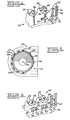
- a track-laying vehicle 10 has a drive sprocket wheel 12, idler 14, and an endless track 16.
- the track has bushings 17.
- the wheel has a hub 18, rim 20, axis of rotation 21, and teeth 22.
- the wheel 12 is used to drive the continuous track 16 and propel the vehicle 10.
- the teeth 22 are positioned about the outer surface 23 of the rim 20 and are arcuately spaced one from the other by root areas 24.
- the root areas 24 have an outer periphery 26 and define a root diameter 2'8.
- the teeth 22 can be of other construction, such as being detachably connected to the rim 20 and positioned in substantially parallel axially spaced apart rows 27 of component teeth, as shown in Figure 4.
- the annular opening 30 is then an annular slot between the rows 27.
- the wheel 12 has an annular opening 30 having inner and outer diameters 32, 33 and inner and outer surfaces 34, 35.
- the opening 30 is in communciation with the outer periphery 26 of the root areas 24.
- a hoop 36 having inner and outer diameters 38, 40 is positioned in the annular opening 30.
- the hoop 36 has an outer surfacc 41.
- the outer diameter 40 of the hoop 36 is greater than the root diameter 28.
- the root diameter 28 reduced by the annular opening inner diameter 32 i.e. the depth of the annular opening radially inwardly of the root diameter 28, is at least as great as the hoop outer diameter 40 reduced by the hoop inner diameter 38, i.e. the radial thickness of the hoop.
- thickness (T) is at least as great as thickness (t).
- the hoop 36 can be of a substantially rigid construction so that upon being forcibly urged to make a first displacement 42 at a first location 43 on the hoop 36, the hoop moves bodily and a substantially similar second displacement 44 occurs at a second opposed location 45 on the hoop 36. Therefore, referring to Figures 1 and 3, the hoop 36 is displaced to a location that is not concentric to the axis 21 in response to contact of the hoop 36 by the track 16.
- the hoop 36 can also be of a flexible resilient construction so that it normally tends to urge itself forcibly against the annular opening outer surface 35 but being locally forcibly flexed towards the axis 21 in response to contact by the track 16.
- the hoop 36 is generally radially movable in the annular opening 30 adjacent the root area 24 at which the hoop 36 is contacted by the track 16.
- the hoop 36 can have radially outwardly projecting teeth 46 positioned about its outer surface 41. It is desirable that the teeth 46 be of a number at least equal to the number of teeth 22 on the wheel 12. Hoop teeth 46 in excess of the number of wheel teeth 22 provides rotation or partial rotation of the hoop 36 relative to the wheel 12 during rotation of the wheel 12 and engagement of the track 16. This relative movement of the hoop 36 can also be provided by hoop teeth 46 being of a greater size than teeth 22 of the wheel 12.
- relief openings 50 in the wheel 12 for discharge of material otherwise trapped between the hoop 36 and inner surface of the annular opening 30. As shown in Figures 3 and 4, such relief openings 50 lead from the inner surface 34 of the annular opening 30 to the face of the wheel, in positions adjacent to the root areas.
- the relief openings 50 can be adjacent each respective root area 24. Adjacent relief openings 50 in adjacent rows 27 are in communication with one another across the inner surface of the annular opening.
- the relief openings 50 are in communication with the side faces of the wheel 12 in order for discharge of material.
- the hoop 36 forcibly lifts against material located in the root areas 24 of the wheel 12. This action displaces the material, removing it from the root areas 24 of the teeth 22. Therefore, the tendency of material to pack in the root areas 24 and increase track pitch is substantially overcome.
- the rotating drive wheel 12 engages the track 16 to drive the vehicle 10 ( Figure 1).
- the hoop 36 is forced into the annular opening 30 by the track 16.
- Opposite portions of the hoop 36 are correspondingly displaced radially outwardly in the annular opening 30. More particularly, the hoop 36 is displaced a predetermined distance in the annular opening 30. This distance is dependent upon the inner and outer diameters 32, 33, 38, 40 of the annular opening 30 and of the hoop 36.
- relief openings 50 help clean mud or dirt from adjacent the root areas 24 which can sometimes collect between the hoop 36 and wheel 12.
- the hoop 36 is urged into the annular opening 38 during engagement. This action tends to force such material through the relief openings 50 and away from the root areas 24 ( Figures 3 and 5).
- the hoop 36 continuously forcibly urges against the outer surface 35 of the annular opening 30.
- the hoop 36 is displaced into the annular opening 30 during track engagement.
- the hoop 36 tends to return to the normal position against the outer surface 35, thereby displacing material placed in the root area 24 during track engagement.
Landscapes
- Engineering & Computer Science (AREA)
- Chemical & Material Sciences (AREA)
- Combustion & Propulsion (AREA)
- Transportation (AREA)
- Mechanical Engineering (AREA)
- Gears, Cams (AREA)
- Vehicle Cleaning, Maintenance, Repair, Refitting, And Outriggers (AREA)
Applications Claiming Priority (2)
| Application Number | Priority Date | Filing Date | Title |
|---|---|---|---|
| US05/909,760 US4175796A (en) | 1978-05-26 | 1978-05-26 | Track-type vehicle wheel cleaning apparatus |
| US909760 | 1986-09-19 |
Publications (2)
| Publication Number | Publication Date |
|---|---|
| EP0005892A1 EP0005892A1 (en) | 1979-12-12 |
| EP0005892B1 true EP0005892B1 (en) | 1981-07-01 |
Family
ID=25427791
Family Applications (1)
| Application Number | Title | Priority Date | Filing Date |
|---|---|---|---|
| EP79300472A Expired EP0005892B1 (en) | 1978-05-26 | 1979-03-23 | Self cleaning toothed wheel |
Country Status (5)
| Country | Link |
|---|---|
| US (1) | US4175796A (online.php) |
| EP (1) | EP0005892B1 (online.php) |
| JP (1) | JPS54155533A (online.php) |
| BR (1) | BR7903254A (online.php) |
| CA (1) | CA1101911A (online.php) |
Families Citing this family (29)
| Publication number | Priority date | Publication date | Assignee | Title |
|---|---|---|---|---|
| US4506934A (en) * | 1983-01-07 | 1985-03-26 | Fmc Corporation | Chordal action isolation wheel assembly |
| USRE33324E (en) * | 1983-07-25 | 1990-09-04 | Edwards, Harper, McNew & Co. | Endless drive system |
| US4765695A (en) * | 1985-07-03 | 1988-08-23 | General Dynamics Land Systems, Inc. | Center guide for shoe assembly of track laying vehicle |
| US5005921A (en) | 1987-05-14 | 1991-04-09 | Edwards, Harper, Mcnew & Company | Endless track drive system |
| US4906054A (en) * | 1987-05-14 | 1990-03-06 | Edwards, Harper, Mcnew & Company | Endless track drive system |
| US4861120A (en) * | 1987-05-14 | 1989-08-29 | Edwards, Harper, Mcnew & Company | Modular endless track drive system and methods of making, installing and repairing same |
| US5005922A (en) | 1987-05-14 | 1991-04-09 | Edwards, Harper, Mcnew & Company | Double V-shaped endless track drive system |
| US5040282A (en) | 1987-05-14 | 1991-08-20 | Edwards, Harper, Mcnew & Company | Method of making a modular endless track drive system |
| US4884852A (en) | 1987-05-14 | 1989-12-05 | Edwards, Harper, Mcnew & Company | Double V-shaped endless track drive system |
| US4844560A (en) * | 1987-10-28 | 1989-07-04 | Edwards, Harper, Mcnew & Company | Endless drive track joint assembly |
| US5020865A (en) * | 1988-01-20 | 1991-06-04 | Edwards, Harper, Mcnew & Company | Endless drive track joint assembly |
| DE19733264A1 (de) * | 1997-08-01 | 1999-02-04 | Sipra Patent Beteiligung | Fadenliefervorrichtung und dafür geeignetes Antriebsrad |
| US6250726B1 (en) * | 1997-08-21 | 2001-06-26 | Caterpillar Inc. | Sprocketed idler for a track assembly |
| KR100337348B1 (ko) * | 1999-09-10 | 2002-05-21 | 이계안 | 롤러 체인용 스프로킷 |
| US6279726B1 (en) | 2000-03-15 | 2001-08-28 | Ashworth Bros., Inc. | Self-cleaning drive mechanism for driving conveyor belts |
| US6770024B1 (en) * | 2000-03-28 | 2004-08-03 | Stony Brook Surgical Innovations, Inc. | Implantable counterpulsation cardiac assist device |
| DE10026084C1 (de) * | 2000-05-24 | 2001-08-09 | Atecs Mannesmann Ag | Antriebsturas |
| US6543862B1 (en) * | 2000-07-28 | 2003-04-08 | Agtracks, Inc. | Drive wheel for track apparatus |
| US6536853B2 (en) * | 2001-04-20 | 2003-03-25 | Caterpillar Inc | Arrangement for supporting a track chain of a track type work machine |
| JP4688356B2 (ja) * | 2001-07-03 | 2011-05-25 | 住友ゴム工業株式会社 | 弾性クローラ走行装置およびこの弾性クローラ走行装置に用いる履帯用スプロケット |
| DE10163968B4 (de) * | 2001-12-20 | 2004-08-12 | Kässbohrer Geländefahrzeug AG | Turasrad für ein Kettenlaufwerk |
| JP3939182B2 (ja) * | 2002-03-29 | 2007-07-04 | 株式会社小松製作所 | 履帯式走行装置 |
| US8100483B2 (en) * | 2007-10-18 | 2012-01-24 | Caterpillar Inc. | Machine and track assembly for use therewith |
| CN102452548A (zh) * | 2010-10-21 | 2012-05-16 | 江苏鑫三和机械有限公司 | 一种刮板输送机用模锻链尾轮 |
| DE102011012711B3 (de) * | 2011-03-01 | 2012-07-12 | Bucyrus Hex Gmbh | Raupenfahrwerk |
| CN103287520B (zh) * | 2012-03-05 | 2016-01-13 | 徐工集团工程机械股份有限公司 | 驱动轮组件、起重机的履带式驱动机构及其配合调节方法 |
| JP2016509180A (ja) * | 2013-03-01 | 2016-03-24 | ボーグワーナー インコーポレーテッド | ノイズ、振動、調波を低減するスプロケット技術 |
| AT16486U1 (de) * | 2016-10-24 | 2019-10-15 | Lhb Mining Solutions Gmbh | Fördersystem |
| CN108945130A (zh) * | 2017-02-06 | 2018-12-07 | 温州泓呈祥科技有限公司 | 一种防缠绕履带驱动轮 |
Family Cites Families (11)
| Publication number | Priority date | Publication date | Assignee | Title |
|---|---|---|---|---|
| US1607940A (en) * | 1922-09-07 | 1926-11-23 | Caterpillar Tractor Co | Tracklaying tractor |
| US1841925A (en) * | 1927-03-14 | 1932-01-19 | Adin C Woodbury | Chain drive |
| US1853308A (en) * | 1930-04-12 | 1932-04-12 | Walter G Humphreys | Sprocket wheel |
| DE900535C (de) * | 1951-09-16 | 1953-12-28 | Dipl Landw Kurt Wiessell | Antrieb fuer Raupenfahrzeuge |
| FR1253258A (fr) * | 1959-12-11 | 1961-02-10 | Barbotin pour véhicule à chenilles | |
| US3880478A (en) * | 1974-01-07 | 1975-04-29 | Case Co J I | Crawler chain sprocket with relief openings |
| US3899219A (en) * | 1974-05-28 | 1975-08-12 | Caterpillar Tractor Co | Self-cleaning sprocket means |
| US4042282A (en) * | 1975-12-24 | 1977-08-16 | Caterpillar Tractor Co. | Track bushing providing external deposits of wear resistant material |
| JPS5291231A (en) * | 1976-01-26 | 1977-08-01 | Caterpillar Mitsubishi Ltd | Apparatus for preventing generation of noises around sprockets of crawler vehicle |
| US4058352A (en) * | 1976-08-09 | 1977-11-15 | Caterpillar Tractor Co. | Track-type vehicle wheel having impact resistance means |
| US4080008A (en) * | 1976-08-09 | 1978-03-21 | Caterpillar Tractor Co. | Biased actuating wheels |
-
1978
- 1978-05-26 US US05/909,760 patent/US4175796A/en not_active Expired - Lifetime
-
1979
- 1979-03-23 EP EP79300472A patent/EP0005892B1/en not_active Expired
- 1979-03-29 CA CA324,406A patent/CA1101911A/en not_active Expired
- 1979-05-15 JP JP5873379A patent/JPS54155533A/ja active Granted
- 1979-05-24 BR BR7903254A patent/BR7903254A/pt unknown
Also Published As
| Publication number | Publication date |
|---|---|
| JPS54155533A (en) | 1979-12-07 |
| EP0005892A1 (en) | 1979-12-12 |
| CA1101911A (en) | 1981-05-26 |
| BR7903254A (pt) | 1979-12-11 |
| JPS6238191B2 (online.php) | 1987-08-17 |
| US4175796A (en) | 1979-11-27 |
Similar Documents
| Publication | Publication Date | Title |
|---|---|---|
| EP0005892A1 (en) | Self cleaning toothed wheel | |
| US7823990B2 (en) | Sprocketed idler assembly | |
| EP0077617B1 (en) | Lubricant retainer and gear case fitted therewith | |
| CN101374718B (zh) | 无芯骨橡胶履带及行驶装置 | |
| EP0058520A2 (en) | Tread belt link and cooperating drive tumbler | |
| US3880478A (en) | Crawler chain sprocket with relief openings | |
| US5553931A (en) | Track roller assembly | |
| AU2017321113B2 (en) | Splined idler for scallop resistance | |
| JP3939182B2 (ja) | 履帯式走行装置 | |
| GB1562360A (en) | Sprocket profile | |
| EP0679131B1 (en) | Track roller assembly having a replaceable flange | |
| EP1495949B1 (en) | Running device of rubber crawler | |
| EP1240068A1 (en) | Reduced sound transmitting sprocket for track-type machines | |
| WO1990003911A1 (en) | Track carrier roller with resilient and replaceable tread | |
| US3889550A (en) | Impact absorbing noise suppression device | |
| US3486574A (en) | Drive mechanism for crawler tracks | |
| US4081202A (en) | Noise reduction device for a chain drive mechanism | |
| US4035036A (en) | Noise suppressing element for continuous track of crawler type vehicle and method of operating same | |
| CA1098567A (en) | Armored cushioning lug for track-type vehicles | |
| JPS5858269B2 (ja) | ゴム弾性履帯 | |
| US2827337A (en) | Sprocket drive for endless track top rollers | |
| JPH0442230B2 (online.php) | ||
| JP2768511B2 (ja) | クローラ走行装置 | |
| JPS6189182A (ja) | 履帯外れ防止装置 | |
| SU1652170A1 (ru) | Съемный гусеничный ход транспортного средства |
Legal Events
| Date | Code | Title | Description |
|---|---|---|---|
| PUAI | Public reference made under article 153(3) epc to a published international application that has entered the european phase |
Free format text: ORIGINAL CODE: 0009012 |
|
| 17P | Request for examination filed | ||
| AK | Designated contracting states |
Designated state(s): FR GB IT |
|
| ITF | It: translation for a ep patent filed | ||
| GRAA | (expected) grant |
Free format text: ORIGINAL CODE: 0009210 |
|
| AK | Designated contracting states |
Designated state(s): FR GB IT |
|
| PGFP | Annual fee paid to national office [announced via postgrant information from national office to epo] |
Ref country code: FR Payment date: 19841205 Year of fee payment: 7 |
|
| REG | Reference to a national code |
Ref country code: GB Ref legal event code: 732 |
|
| ITPR | It: changes in ownership of a european patent |
Owner name: CESSIONE;CATERPILLAR INC. |
|
| REG | Reference to a national code |
Ref country code: FR Ref legal event code: TP |
|
| PG25 | Lapsed in a contracting state [announced via postgrant information from national office to epo] |
Ref country code: GB Free format text: LAPSE BECAUSE OF NON-PAYMENT OF DUE FEES Effective date: 19881118 |
|
| GBPC | Gb: european patent ceased through non-payment of renewal fee | ||
| PG25 | Lapsed in a contracting state [announced via postgrant information from national office to epo] |
Ref country code: FR Free format text: LAPSE BECAUSE OF NON-PAYMENT OF DUE FEES Effective date: 19881130 |
|
| REG | Reference to a national code |
Ref country code: FR Ref legal event code: ST |
|
| PLBE | No opposition filed within time limit |
Free format text: ORIGINAL CODE: 0009261 |
|
| STAA | Information on the status of an ep patent application or granted ep patent |
Free format text: STATUS: NO OPPOSITION FILED WITHIN TIME LIMIT |