EP0005692A1 - Conversion installation with a tiltable converter - Google Patents
Conversion installation with a tiltable converter Download PDFInfo
- Publication number
- EP0005692A1 EP0005692A1 EP79890006A EP79890006A EP0005692A1 EP 0005692 A1 EP0005692 A1 EP 0005692A1 EP 79890006 A EP79890006 A EP 79890006A EP 79890006 A EP79890006 A EP 79890006A EP 0005692 A1 EP0005692 A1 EP 0005692A1
- Authority
- EP
- European Patent Office
- Prior art keywords
- housing
- converter
- ceiling
- charging
- crane
- Prior art date
- Legal status (The legal status is an assumption and is not a legal conclusion. Google has not performed a legal analysis and makes no representation as to the accuracy of the status listed.)
- Granted
Links
Images


Classifications
-
- C—CHEMISTRY; METALLURGY
- C21—METALLURGY OF IRON
- C21C—PROCESSING OF PIG-IRON, e.g. REFINING, MANUFACTURE OF WROUGHT-IRON OR STEEL; TREATMENT IN MOLTEN STATE OF FERROUS ALLOYS
- C21C5/00—Manufacture of carbon-steel, e.g. plain mild steel, medium carbon steel or cast steel or stainless steel
- C21C5/28—Manufacture of steel in the converter
- C21C5/38—Removal of waste gases or dust
- C21C5/40—Offtakes or separating apparatus for converter waste gases or dust
Definitions
- the invention relates to a converter system with a tiltable converter, which is surrounded by a housing, on the ceiling of which a main exhaust line for discharging fresh gases is connected, part of the housing being attached to a charging device and being movable therewith.
- exhaust gases which mainly consist of carbon oxides and entrained FeO particles, emerge from the converter mouth during the refreshing process. These exhaust gases, also known as main emissions, have to be cleaned and the energy contained therein may have to be extracted before they can be released into the atmosphere. Even when charging a converter with scrap and pig iron and tapping the molten steel into the ladle, there is sometimes a lot of smoke, which exhaust gases are referred to as secondary emissions.
- An even greater burden from smoke and smoke development is in steelworks with floor-blowing converters, e.g. given when carrying out the OBM process, since the introduction of auxiliary substances into the floor nozzles causes sparks in the form of sparks.
- the known devices for discharging the exhaust gases comprise cover hoods which surround the converter mouth and are connected to exhaust lines which can neither reliably absorb the main emissions nor the secondary emissions.
- a device has also become known (DE-OS 22 33 443), in which a steelwork converter is installed on all sides with a small spacing which, however, permits a tilting movement. The converter is charged through a side opening into which the snout of the charging container or a charging channel can be inserted. The charging opening remains open during charging, and therefore it cannot be prevented that the pollutants of the secondary emissions also escape through the charging opening, get into the atmosphere and endanger safety. This danger is particularly present in OBM converters when the floor nozzles are applied.
- a system in which a stationary melting furnace, in particular an electric arc furnace, is surrounded by a housing, the furnace being able to be run over by a crane. Sheets are attached to the crane at intervals, which alternately close a housing opening when the crane is extended and retracted.
- Such devices are not suitable for converter systems in which large amounts of exhaust gases occur during the fresh phase. Powerful converter systems need two Exhaust lines, u. between primary and secondary emissions.
- the invention aims to avoid the disadvantages described and has as its object to provide a converter system in which both the gases produced during the freshening and during charging and A -pouring are reliably detected and an exit of these gases from the system in the hall is reliably avoided, where appropriate the charging crane can be used for several converters standing side by side.
- the charging device is designed as a gantry crane which can be moved in the longitudinal direction of the hall, ie in the direction of the tilting axis of the converter or converters, to which a cellular housing part is fastened which is open on the converter side and has a gas exhaust opening in the ceiling, is otherwise closed, however, in the charging position and possibly also in the A b pouring position, the cellular part closes the housing and the exhaust opening in the ceiling comes to rest below a secondary exhaust line for discharging the secondary emissions.
- a semi-gantry crane is expediently mounted on the work platform and an intermediate crane runway girder, which is arranged on the housing ceiling.
- the cell walls can be constructed in several parts to accommodate charging containers or the like placed on the working platform with the aid of the lifting mechanism of the semi-portal crane, one wall part being movable for the lateral insertion of the charging container.
- Another inexpensive way of receiving charging containers is that an opening for lifting charging containers or the like is provided in the work platform with the aid of the lifting mechanism of the pc-crane from the hallway.
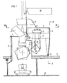
- FIG. 1 shows a side view of the converter system with the housing side walls removed in section according to I-I in FIG. 3
- FIG. 2 shows a front view of the cellular part of the housing with the front wall removed according to II-II in FIG. 1 and the connection of the exhaust opening to the secondary exhaust line
- Fig. 3 shows the plant in plan according to III-III in Fig. 1
- Fig. 4 illustrates in side view a charging container on the work platform after lifting a cell wall part
- 5 shows a side view of a charging container to be received from the hut hallway through an opening in the work platform.
- a converter 1 that can be tilted about a horizontal axis is surrounded by a housing 2, to the cover 3 of which a main exhaust line 4 is connected for discharging the main emissions that occur during freshening.
- a cell-shaped part 6 is fastened to a semi-portal crane 5 which can be moved in the longitudinal direction of the hall and which can have an approximately U-shaped layout and is open on the converter side 7.
- This part 6 has an opening 9 in the ceiling 8.
- the cell side walls 10 and 10 ' close to the housing front wall 11, so that the housing is closed on all sides, the ceiling opening 9 of the cellular part 6 coming to be below the secondary exhaust line 12 and the connection being closed this manufactures.
- This side deduction Line 12 can open into the main exhaust line 4, wherein the exhaust gases can be fed to a common filter system.
- the semi-portal crane 5 is mounted on the work platform 13 and an intermediate crane runway beam 14, which is fastened to the housing ceiling 3, by means of rollers 15, 15 '. It can be moved between loading stations and the charging position or several charging positions with a plurality of converters in the longitudinal direction of the hall.
- a side wall 10 of the cellular part 6 is formed in two parts, the lower part being designed as a door 21 that can be raised and lowered.
- the semi-portal crane 5 with the cellular part 6 attached to it can run over and pick up a charging container 16 placed on the work platform 13.
- FIG. 5 there is an opening 22 in the work platform 13.
- a charging container 16 placed on the hut floor 23 can be received with the lifting mechanism 18 from below and then moved into the charging position.
- the operation of the system is such that converter 1 is first loaded with scrap.
- the overhead crane 20 installed on the upper crane runway 19 brings a loaded scrap chute 24 to a transfer point. This can work on stage 13 or on hut floor 23, as shown in FIGS. 4 and 5.
- the semi-portal crane 5 takes over the scrap chute 24 and moves it into the charging position, in which the charging takes place by tilting the scrap chute into the mouth of the likewise tilted converter. This position is indicated in Fig. 1 with dash-dotted lines.
- the exhaust gases generated during charging, the secondary emissions, flow through the cellular part 6 of the housing, sweep past the trolley 17 and reach the secondary exhaust line 12, the hall itself remaining free of smoke.
- the converter 1 is then charged with pig iron, the pig iron pan 16 being taken over in the same way from a transfer point with the semi-portal crane 5. After the converter has been tilted into the vertical blowing position (shown in dashed lines in FIG. 1), refreshing takes place, the resulting exhaust gases being taken up by the main exhaust line 4.
- Smoke can also develop when pouring the liquid steel. between when performing an OBM procedure than when performing an LD procedure. While in the LD method it will generally not be necessary to close the housing completely, one type of use of the device according to the invention can be to bring the semi-portal crane 5 with the cellular part 6 into the closed position even when the steel is poured, without a container is on the crane. With this type of application, the casting takes place with the housing closed.
Abstract
Bei einer Konverteranlage mit einem kippbaren Konverter (1), welcher von einem Gehäuse (2, 3, 6) umgeben ist, ist an der Decke (3) des Gehäuses ein Hauptabzugsleitung (4) zum Ableiten von Frischgasen angeschlossen, wobei ein Teil (6) des Gehäuses an einer Chargiereinrichtung (5) befestigt und mit dieser verfahrbar ist. Um sowohl während des Frischens als auch während des Chargierens und Abgießens entstehende Gase sicher zu erfassen und den Austritt dieser Gase in die Halle zu vermeiden, wobei die Chargiereinrichtung (5) für mehrere nebeneinander angeordnete Konverter einsetzbar ist, ist die Chargiereinrichtung als ein in Hallenlängsrichtung, d.h. in Richtung der Kippachse des bzw. der Konverter (1) verfahrbarer Portalkran (5) ausgebildet, an dem ein zellenförmiger Gehäuseteil (6) befestigt ist, der konverterseitig (7) offen ist und in der Decke (8) eine Gasabzugsöffnung (9) aufweist, sonst jedoch geschlossen ist, wobei in der Chargierstellung und gegebenenfalls auch in der Abgießstellung der zellenförmige Teil (6) das Gehäuse (2) schließt und die Abzugsöffnung (9) in der Decke (8) unterhalb einer Nebenabzugsleitung (12) zum Ableiten der Sekundäremissionen zu stehen kommt.In a converter system with a tiltable converter (1) which is surrounded by a housing (2, 3, 6), a main exhaust line (4) for discharging fresh gases is connected to the ceiling (3) of the housing, a part (6 ) of the housing attached to a charging device (5) and can be moved with it. In order to reliably detect gases generated both during freshening and during charging and pouring and to prevent these gases from escaping into the hall, wherein the charging device (5) can be used for several converters arranged next to one another, the charging device is designed as one in the longitudinal direction of the hall, ie Portal crane (5) movable in the direction of the tilt axis of the converter or converters (1), to which a cellular housing part (6) is fastened, which is open on the converter side (7) and has a gas extraction opening (9) in the ceiling (8) , but is otherwise closed, with the cellular part (6) closing the housing (2) and the exhaust opening (9) in the ceiling (8) below a secondary exhaust line (12) for discharging the secondary emissions in the charging position and possibly also in the pouring position comes to a standstill.
Description
Die Erfindung betrifft eine Konverteranlage mit einem kippbaren Konverter, welcher von einem Gehäuse umgeben ist, an dessen Decke eine Hauptabzugsleitung zum Ableiten von Frischgasen angeschlossen ist, wobei ein Teil des Gehäuses an einer Chargiereinrichtung befestigt und mit dieser verfahrbar ist.The invention relates to a converter system with a tiltable converter, which is surrounded by a housing, on the ceiling of which a main exhaust line for discharging fresh gases is connected, part of the housing being attached to a charging device and being movable therewith.
Beim Betrieb eines Stahlwerkskonverters treten während des Frischens Abgase aus der Konvertermündung aus, die hauptsächlich aus Kohlenoxiden und mitgeführten FeO-Teilchen bestehen. Diese auch als Hauptemissionen bezeichneten Abgase müssen gereinigt und eventuell die darin enthaltene Energie gewonnen werden, bevor sie in die Atmosphäre abgelassen werden dürfen. Auch beim Chargieren eines Konverters mit Schrott und Roheisen und beim Abstich des flüssigen Stahles in die Gießpfanne kommt es zu einer mitunter starken Rauchentwicklung, wobei diese Abgase als Nebenemissionen bezeichnet werden. Eine noch stärkere Belastung durch Rauch- und Qualmentwicklung ist in Stahlwerken mit bodenblasenden Konvertern, z.B. bei Durchführung des OBM-Verfahrens gegeben, da die Einführung von Hilfsstoffen in die Bodendüsen Auswürfe in Form von Funkenregen verursacht.When operating a steelworks converter, exhaust gases, which mainly consist of carbon oxides and entrained FeO particles, emerge from the converter mouth during the refreshing process. These exhaust gases, also known as main emissions, have to be cleaned and the energy contained therein may have to be extracted before they can be released into the atmosphere. Even when charging a converter with scrap and pig iron and tapping the molten steel into the ladle, there is sometimes a lot of smoke, which exhaust gases are referred to as secondary emissions. An even greater burden from smoke and smoke development is in steelworks with floor-blowing converters, e.g. given when carrying out the OBM process, since the introduction of auxiliary substances into the floor nozzles causes sparks in the form of sparks.
In neuerer Zeit und in köher ehtwickolton Industrieländern bestehen strenge Vorschriften zur Vermeidung bzw. zur Herabsetzung der Emissionen und ebenso Vorschriften für die Erhöhung der Sicherheit des Bec lebspersonales. Die bekannten Einrichtungen zum Ableiten von Konverterabgasen werden diesen erhöhten Anforderungen nicht gerecht.More recently and in higher ehtwickolton industrialized countries there are strict regulations for avoiding or reducing emissions as well as regulations for increasing the safety of living personnel. The known devices for deriving converter exhaust gases do not meet these increased requirements.
Die bekannten Einrichtungen zum Ableiten der Abgase umfassen Abdeckhauben, die die Konvertermündung umgeben und an Abzugsleitungen angeschlossen sind, die weder die Hauptemissionen noch die Nebenemissionen verläßlich aufnehmen können. Es ist auch eine Einrichtung bekannt geworden (DE-OS 22 33 443), bei der ein Stahlwerkskonverter allseitig mit geringem, jedoch eine Kippbewegung zulassendem Abstand eingebaut ist. Die Chargierung des Konverters erfolgt durch eine seitliche öffnung, in die die Schnauze des Chargierbehälters oder eine Chargierrinne einführbar ist. Während des Chargierens bleibt die Chargieröffnung offen, und es ist daher nicht zu verhindern, daß die Schadstoffe der Nebenemissionen auch durch die Chargieröffnung austreten, in die Atmosphäre gelangen und die Sicherheit gefährden. Diese Gefahr ist besonders bei OBM-Konvertern bei Beaufschlagung der Bodendüsen vorhanden.The known devices for discharging the exhaust gases comprise cover hoods which surround the converter mouth and are connected to exhaust lines which can neither reliably absorb the main emissions nor the secondary emissions. A device has also become known (DE-OS 22 33 443), in which a steelwork converter is installed on all sides with a small spacing which, however, permits a tilting movement. The converter is charged through a side opening into which the snout of the charging container or a charging channel can be inserted. The charging opening remains open during charging, and therefore it cannot be prevented that the pollutants of the secondary emissions also escape through the charging opening, get into the atmosphere and endanger safety. This danger is particularly present in OBM converters when the floor nozzles are applied.
Weiters ist eine Anlage bekannt (AT-PS 329.895), bei der ein ortsfester Schmelzofen, insbesondere ein Elektro-Lichtbogenofen von einem Gehäuse umgeben ist, wobei der Ofen von einem Kran überfahrbar ist. An dem Kran sind in Abständen voneinander Bleche befestigt, die beim Ein- und Ausfahren des Kranes wechselweise eine Gehäuseöffnung schließen. Solche Einrichtungen sind jedoch für Konverteranlagen, bei denen große Mengen von Abgasen während der Frischphase entstehen, nicht geeignet. Leistungsfähige Konverteranlagen müssen zwei Abzugsleitungen, u. zw. für die Primär- und für die Sekundäremissionen, aufweisen.Furthermore, a system is known (AT-PS 329.895), in which a stationary melting furnace, in particular an electric arc furnace, is surrounded by a housing, the furnace being able to be run over by a crane. Sheets are attached to the crane at intervals, which alternately close a housing opening when the crane is extended and retracted. However, such devices are not suitable for converter systems in which large amounts of exhaust gases occur during the fresh phase. Powerful converter systems need two Exhaust lines, u. between primary and secondary emissions.
Die Erfindung bezweckt die Vermeidung der geschilderten Nachteile und stellt sich die Aufgabe, eine Konverteranlage zu schaffen, bei der sowohl die während des Frischens als auch während des Chargierens und Ab-gießens entstehenden Gase sicher erfaßt werden und ein Austritt dieser Gase aus der Anlage in die Halle zuverlässig vermieden wird, wobei gegebenenfalls der Chargierkran für mehrere nebeneinander stehende Konverter einsetzbar ist.The invention aims to avoid the disadvantages described and has as its object to provide a converter system in which both the gases produced during the freshening and during charging and A -pouring are reliably detected and an exit of these gases from the system in the hall is reliably avoided, where appropriate the charging crane can be used for several converters standing side by side.
Diese Aufgabe wird erfindungsgemäß dadurch gelöst, daß die Chargiereinrichtung als ein in Hallenlängsrichtung, d.h. in Richtung der Kippachse des bzw. der Konverter verfahrbarer Portalkran ausgebildet ist, an dem ein zellenförmiger Gehäuseteil befestigt ist, der konverterseitig offen ist und in der Decke eine Gasabzugsöffnung aufweist, sonst jedoch geschlossen ist, wobei in der Chargierstellung und gegebenenfalls auch in der Ab-gießstellung der zellenförmige Teil das Gehäuse schließt und die Abzugsöffnung in der Decke unterhalb einer Nebenabzugsleitung zum Ableiten der Sekundäremissionen zu stehen kommt.This object is achieved in that the charging device is designed as a gantry crane which can be moved in the longitudinal direction of the hall, ie in the direction of the tilting axis of the converter or converters, to which a cellular housing part is fastened which is open on the converter side and has a gas exhaust opening in the ceiling, is otherwise closed, however, in the charging position and possibly also in the A b pouring position, the cellular part closes the housing and the exhaust opening in the ceiling comes to rest below a secondary exhaust line for discharging the secondary emissions.
Zweckmäßig ist ein Halbportalkran auf der Arbeitsbühne und einem Zwischenkranbahnträger, der an der Gehäusedecke angeordnet ist, gelagert.A semi-gantry crane is expediently mounted on the work platform and an intermediate crane runway girder, which is arranged on the housing ceiling.
Zur Aufnahme von auf der Arbeitsbühne abgestellten Chargierbehältern od. dgl. mit Hilfe des Hubwerkes des Halbportalkranes können die Zellenwände mehrteilig ausgebildet sein, wobei ein Wandteil zum seitlichen Einbringen des Chargierbehälters beweglich ist.The cell walls can be constructed in several parts to accommodate charging containers or the like placed on the working platform with the aid of the lifting mechanism of the semi-portal crane, one wall part being movable for the lateral insertion of the charging container.
Eine weitere günstige Möglichkeit zum Aufnehmen von Chargierbehältern besieht darin, daß in der Arbeitsbühne eine öffnung zum Anheben von Chargierbehältern od. dgl. mit Hilfe des Hubwerkes des Pcotalkranes vom Hüttenflur vorgesehen ist.Another inexpensive way of receiving charging containers is that an opening for lifting charging containers or the like is provided in the work platform with the aid of the lifting mechanism of the pc-crane from the hallway.
Die Erfindung ist in der Zeichnung anhand eines Ausführungsbeispieles näher erläutert, wobei Fig. 1 eine Seitenansicht der Konverteranlage bei abgenommenen Gehäuseseitenwänden im Schnitt gemäß I-I in Fig. 3 zeigt; Fig. 2 stellt eine Vorderansicht des zellenförmigen Teiles des Gehäuses bei abgenommener Vorderwand gemäß II-II in Fig. 1 und den Anschluß der Abzugsöffnung an die Nebenabzugsleitung dar; Fig. 3 zeigt die Anlage im Grundriß gemäß III-III in Fig. 1; Fig. 4 veranschaulicht in Seitenansicht einen Chargierbehälter auf der Arbeitsbühne nach Anheben eines Zellenwandteiles; Fig. 5 zeigt in Seitenansicht einen vom Hüttenflur durch eine öffnung in der Arbeitsbühne aufzunehmenden Chargierbehälter.The invention is explained in more detail in the drawing with the aid of an exemplary embodiment, in which FIG. 1 shows a side view of the converter system with the housing side walls removed in section according to I-I in FIG. 3; FIG. 2 shows a front view of the cellular part of the housing with the front wall removed according to II-II in FIG. 1 and the connection of the exhaust opening to the secondary exhaust line; Fig. 3 shows the plant in plan according to III-III in Fig. 1; Fig. 4 illustrates in side view a charging container on the work platform after lifting a cell wall part; 5 shows a side view of a charging container to be received from the hut hallway through an opening in the work platform.
In Fig. 1 ist ein um eine waagrechte Achse kippbarer Konverter 1 von einem Gehäuse 2 umgeben, an dessen Deckel 3 eine Hauptabzugsleitung 4 zum Ableiten der während des Frischens entstehenden Hauptemissionen angeschlossen ist. An einem in Hallenlängsrichtung verfahrbaren Halbportalkran 5 ist ein zellenförmiger Teil 6 befestigt, der im Grundriß etwa U-förmig gestaltet sein kann und an der Konverterseite 7 offen ist. Dieser Teil 6 weist in der Decke 8 eine öffnung 9 auf. In der in den Fig. 1 bis 3 gezeigten Stellung schließen die Zellenseitenwände 10 und 10' an die Gehäusevorderwand 11, sodaß das Gehäuse seitlich allseits geschlossen ist, wobei die Deckenöffnung 9 des zellenförmigen Teiles 6 unterhalb der Nebenabzugsleitung 12 zu stehen kommt und den Anschluß zu dieser herstellt. Diese Nebenabzugsleitung 12 kann in die Hauptabzugsleitung 4 münden, wobei die Abgase einer gemeinsamen Filteranlage zugeführt werden können. Der Halbportalkran 5 ist auf der Arbeitsbühne 13 und einem Zwischenkranbahnträger 14, der an der Gehäusedecke 3 befestigt ist, mittels Rollen 15, 15' gelagert. Er ist zwischen Beladestationen und der Chargierstellung oder mehreren Chargierstellungen bei einer Mehrzahl von Konvertern in Hallenlängsrichtung verfahrbar. Der im Ausführungsbeispiel als Pfanne ausgebildete (mit vollen Linien gezeichnete) Chargierbehälter 16 hängt an der Laufkatze 17 und ist mit einem Hubwerk 18 in die Chargierposition kippbar. Oberhalb der Nebenabzugsleitung 12 ist die Kranbahn 19 für den Hallenlaufkran 20 vorgesehen, der durch den Betrieb des ihn unterfahrenden Halbportalkranes nicht behindert wird.In FIG. 1, a
Wie in den Fig. 2 bis 4 dargestellt ist, ist eine Seitenwand 10 des zellenförmigen Teiles 6 zweiteilig ausgebildet, wobei der untere Teil als heb- und senkbare Tür 21 ausgebildet ist. Bei Anheben der Tür kann der Halbportalkran 5 mit dem daran befestigten zellenförmigen Teil 6 einen auf der Arbeitsbühne 13 abgestellten Chargierbehälter 16 überfahren und aufnehmen.As shown in FIGS. 2 to 4, a
Gemäß Fig. 5 befindet sich in der Arbeitsbühne 13 eine öffnung 22. Bei dieser Variante kann ein auf Hüttenflur 23 abgestellter Chargierbehälter 16 mit dem Hubwerk 18 von unten aufgenommen und dann in die Chargierstellung gefahren werden.According to FIG. 5 there is an opening 22 in the
Der Betrieb der Anlage geht derart vor sich, daß zunächst der Konverter 1 mit Schrott chargiert wird. Zu diesem Zweck bringt der auf der oberen Kranbahn 19 installierte Laufkran 20 eine beladene Schrottschurre 24 zu einer Ubergabestelle. Diese kann auf der Arbeitsbühne 13 oder auf Hüttenflur 23 sein, wie in den Fig. 4 und 5 dargestellt. Der Halbportalkran 5 übernimmt die Schrottschurre 24 und verfährt sie in die Chargierstellung, in der durch Kippen der Schrottschurre in die Mündung des gleichfalls gekippten Konverters die Chargierung erfolgt. Diese Stellung ist in Fig. 1 mit strichpunktierten Linien angedeutet. Die während des Chargierens entstehenden Abgase, die Sekundäremissionen, strömen durch den zellenförmigen Teil 6 des Gehäuses hindurch, streichen an der Laufkatze 17 vorbei und gelangen in die Nebenabzugsleitung 12, wobei die Halle selbst frei von Rauch bleibt.The operation of the system is such that
Anschließend wird der Konverter 1 mit Roheisen chargiert, wobei in gleicher Weise die Roheisenpfanne 16 von einer Übergabestelle mit dem Halbportalkran 5 übernommen wird. Nach Kippen des Konverters in die vertikale Blasstellung (in Fig. 1 strichliert dargestellt) erfolgt das Frischen, wobei die entstehenden Abgase von der Hauptabzugsleitung 4 aufgenommen werden.The
Auch beim Abgießen des flüssigen'Stahles kann es zu einer Rauchentwicklung kommen, u. zw. bei Durchführung eines OBM-Verfahrens mehr als bei Durchführung eines LD-Verfahrens. Während es beim LD-Verfahren im allgemeinen nicht notwendig sein wird, das Gehäuse ganz zu schließen, kann eine Verwendungsart der erfindungsgemäßen Einrichtung darin liegen, auch beim Abgießen des Stahles den Halbportalkran 5 mit dem zellenförmigen Teil 6 in Schließstellung zu bringen, ohne daß ein Behälter sich an dem Kran befindet. Bei dieser Art des Einsatzes erfolgt das Abgießen bei geschlossenem Gehäuse.Smoke can also develop when pouring the liquid steel. between when performing an OBM procedure than when performing an LD procedure. While in the LD method it will generally not be necessary to close the housing completely, one type of use of the device according to the invention can be to bring the
Claims (4)
Applications Claiming Priority (2)
| Application Number | Priority Date | Filing Date | Title |
|---|---|---|---|
| AT376978A AT355071B (en) | 1978-05-24 | 1978-05-24 | CONVERTER SYSTEM WITH A METALLURGICAL VESSEL |
| AT3769/78 | 1978-05-24 |
Publications (2)
| Publication Number | Publication Date |
|---|---|
| EP0005692A1 true EP0005692A1 (en) | 1979-11-28 |
| EP0005692B1 EP0005692B1 (en) | 1981-07-08 |
Family
ID=3555178
Family Applications (1)
| Application Number | Title | Priority Date | Filing Date |
|---|---|---|---|
| EP79890006A Expired EP0005692B1 (en) | 1978-05-24 | 1979-05-21 | Conversion installation with a tiltable converter |
Country Status (6)
| Country | Link |
|---|---|
| US (1) | US4243208A (en) |
| EP (1) | EP0005692B1 (en) |
| JP (1) | JPS54153708A (en) |
| AT (1) | AT355071B (en) |
| CS (1) | CS212701B2 (en) |
| DE (1) | DE2960455D1 (en) |
Families Citing this family (9)
| Publication number | Priority date | Publication date | Assignee | Title |
|---|---|---|---|---|
| US4714010A (en) * | 1985-04-12 | 1987-12-22 | Cm & E/California, Inc. | Industrial exhaust ventilation system |
| AT387925B (en) * | 1987-06-22 | 1989-04-10 | Voest Alpine Ag | PAN LACKING LEVEL |
| AT394396B (en) * | 1990-07-03 | 1992-03-25 | Voest Alpine Stahl Donawitz | METHOD FOR REUSING CABIN DUST AND DEVICE FOR CARRYING OUT THIS METHOD |
| DE4409178A1 (en) * | 1994-03-17 | 1995-09-21 | Siemens Ag | Determining positions of mobile stations in mobile radio system |
| US6071467A (en) * | 1997-12-12 | 2000-06-06 | Uss/Kobe Steel Company | Technique and apparatus for ladle cleanout |
| US6077473A (en) * | 1997-12-12 | 2000-06-20 | Uss/Kobe Steel Company | Torch cutting enclosure having fume collection provisions |
| US6036914A (en) * | 1997-12-12 | 2000-03-14 | Uss/Kobe Steel Company | Dumping bay with fume collecting provisions |
| US6017486A (en) * | 1997-12-12 | 2000-01-25 | Uss/Kobe Steel Company | Comprehensive fume collection system for production of leaded steel |
| JP2019183250A (en) * | 2018-04-17 | 2019-10-24 | 日本製鉄株式会社 | Method for charging scrap into converter |
Citations (5)
| Publication number | Priority date | Publication date | Assignee | Title |
|---|---|---|---|---|
| DE2233443A1 (en) * | 1971-07-26 | 1973-02-15 | Baum Verfahrenstechnik | CONVERTER VESSEL WITH AN OPENING FOR METAL RECEPTION IN A CHAMBER PRACTICALLY COMPLETELY ENCLOSING THE VESSEL AND OPERATING PROCEDURE FOR IT |
| DE2059205B2 (en) * | 1970-12-02 | 1975-08-28 | Demag Ag, 4100 Duisburg | Steel mill crane with trolley, in particular traveling crane for operating furnaces |
| AT329895B (en) * | 1974-02-02 | 1976-06-10 | Krupp Ag Huettenwerke | PLANT FOR THE MELTING METALLURGICAL PRODUCTION OF METALS |
| DE2256269B2 (en) * | 1971-11-17 | 1977-05-05 | Hoogovens Ijmuiden B.V., Ijmuiden (Niederlande) | METAL PRODUCTION PLANT WITH A TILTING CONVERTER |
| DE2816802A1 (en) * | 1977-05-10 | 1978-11-23 | Voest Ag | EXHAUST HOOD FOR DRAINING THE SMOKE OR RISING WHEN CHARGING A METALLURGICAL VESSEL. EXHAUST |
Family Cites Families (1)
| Publication number | Priority date | Publication date | Assignee | Title |
|---|---|---|---|---|
| AT357580B (en) * | 1977-02-04 | 1980-07-25 | Voest Alpine Ag | EXTRACTOR COVER ON A PALE STANDING WITH A TILTABLE CONVERTER |
-
1978
- 1978-05-24 AT AT376978A patent/AT355071B/en not_active IP Right Cessation
-
1979
- 1979-05-17 US US06/039,750 patent/US4243208A/en not_active Expired - Lifetime
- 1979-05-17 CS CS793428A patent/CS212701B2/en unknown
- 1979-05-21 EP EP79890006A patent/EP0005692B1/en not_active Expired
- 1979-05-21 DE DE7979890006T patent/DE2960455D1/en not_active Expired
- 1979-05-24 JP JP6486779A patent/JPS54153708A/en active Pending
Patent Citations (5)
| Publication number | Priority date | Publication date | Assignee | Title |
|---|---|---|---|---|
| DE2059205B2 (en) * | 1970-12-02 | 1975-08-28 | Demag Ag, 4100 Duisburg | Steel mill crane with trolley, in particular traveling crane for operating furnaces |
| DE2233443A1 (en) * | 1971-07-26 | 1973-02-15 | Baum Verfahrenstechnik | CONVERTER VESSEL WITH AN OPENING FOR METAL RECEPTION IN A CHAMBER PRACTICALLY COMPLETELY ENCLOSING THE VESSEL AND OPERATING PROCEDURE FOR IT |
| DE2256269B2 (en) * | 1971-11-17 | 1977-05-05 | Hoogovens Ijmuiden B.V., Ijmuiden (Niederlande) | METAL PRODUCTION PLANT WITH A TILTING CONVERTER |
| AT329895B (en) * | 1974-02-02 | 1976-06-10 | Krupp Ag Huettenwerke | PLANT FOR THE MELTING METALLURGICAL PRODUCTION OF METALS |
| DE2816802A1 (en) * | 1977-05-10 | 1978-11-23 | Voest Ag | EXHAUST HOOD FOR DRAINING THE SMOKE OR RISING WHEN CHARGING A METALLURGICAL VESSEL. EXHAUST |
Also Published As
| Publication number | Publication date |
|---|---|
| US4243208A (en) | 1981-01-06 |
| DE2960455D1 (en) | 1981-10-15 |
| AT355071B (en) | 1980-02-11 |
| EP0005692B1 (en) | 1981-07-08 |
| CS212701B2 (en) | 1982-03-26 |
| ATA376978A (en) | 1979-07-15 |
| JPS54153708A (en) | 1979-12-04 |
Similar Documents
| Publication | Publication Date | Title |
|---|---|---|
| DE2313660C3 (en) | Multi-aisle beam generation system with one or more electric arc furnaces | |
| DE2256269C3 (en) | Metal production plant with a tiltable converter | |
| EP0005692B1 (en) | Conversion installation with a tiltable converter | |
| WO2009138297A1 (en) | Furnace system | |
| DE2233443B2 (en) | Converter system | |
| DE2935297C2 (en) | System for charging electric arc furnaces | |
| EP0005693B1 (en) | Conversion installation with a tiltable converter vessel | |
| EP0153552B1 (en) | Plant comprising a refractory-lined metallurgical vessel | |
| DE4104910C3 (en) | Steel treatment plant | |
| EP0006084B1 (en) | Apparatus for collecting and withdrawing off-gases | |
| DE2803960C2 (en) | Plant for refining pig iron | |
| DE3903444C1 (en) | Method and apparatus for transporting liquid metal from a metallurgical furnace to a casting vessel | |
| EP0760395B1 (en) | Installation for the liquid metal transportation in the casthouse of a shaft furnace and process for handling this installation | |
| DE2135839C3 (en) | Process for the detection of the flue gases produced during the batching of scrap and steel cutting off of electric furnaces with direct suction | |
| EP0003357A1 (en) | Housing for receiving a metallurgical vessel | |
| DE2100015B2 (en) | SUCTION AND DUST DUST DEVICE FOR AN ELECTRIC ARC FURNACE, IN PARTICULAR FOR STEEL PRODUCTION | |
| DE2623545C3 (en) | Exhaust hood for a ladle and pouring device | |
| DE2800693A1 (en) | EXHAUST HOOD ON A FOLDED STAND WITH A TILTING CONVERTER | |
| DE1182272B (en) | Plant for refining pig iron | |
| DE2506704B2 (en) | METAL MELTING PLANT WITH A TREATMENT STAND FOR SETTING THE ANALYSIS OF METAL MELT, IN PARTICULAR FOR DESULFURIZING LIQUID CRUDE IRON OR CRUDE STEEL | |
| EP0025028B2 (en) | Ladle position for performing metallurgical treatments of steel melts | |
| DE2705565C3 (en) | Exhaust system for tiltable metallurgical furnaces, especially for steel works converters | |
| AT208376B (en) | Plant for refining pig iron | |
| DE3146760C2 (en) | Hood construction for a hut converter | |
| DE2405038C2 (en) | Plant for the smelting metallurgical production of metals |
Legal Events
| Date | Code | Title | Description |
|---|---|---|---|
| PUAI | Public reference made under article 153(3) epc to a published international application that has entered the european phase |
Free format text: ORIGINAL CODE: 0009012 |
|
| AK | Designated contracting states |
Designated state(s): BE DE FR GB IT LU SE |
|
| 17P | Request for examination filed | ||
| ITF | It: translation for a ep patent filed |
Owner name: SOCIETA' ITALIANA BREVETTI S.P.A. |
|
| GRAA | (expected) grant |
Free format text: ORIGINAL CODE: 0009210 |
|
| AK | Designated contracting states |
Designated state(s): BE DE FR GB IT LU SE |
|
| REF | Corresponds to: |
Ref document number: 2960455 Country of ref document: DE Date of ref document: 19811015 |
|
| PG25 | Lapsed in a contracting state [announced via postgrant information from national office to epo] |
Ref country code: LU Free format text: LAPSE BECAUSE OF NON-PAYMENT OF DUE FEES Effective date: 19820531 |
|
| PLBI | Opposition filed |
Free format text: ORIGINAL CODE: 0009260 |
|
| 26 | Opposition filed |
Opponent name: MANNESMANN AKTIENGESELLSCHAFT Effective date: 19820403 |
|
| PGFP | Annual fee paid to national office [announced via postgrant information from national office to epo] |
Ref country code: FR Payment date: 19830331 Year of fee payment: 5 Ref country code: BE Payment date: 19830331 Year of fee payment: 5 |
|
| PLBN | Opposition rejected |
Free format text: ORIGINAL CODE: 0009273 |
|
| STAA | Information on the status of an ep patent application or granted ep patent |
Free format text: STATUS: OPPOSITION REJECTED |
|
| PGFP | Annual fee paid to national office [announced via postgrant information from national office to epo] |
Ref country code: DE Payment date: 19830412 Year of fee payment: 5 |
|
| PGFP | Annual fee paid to national office [announced via postgrant information from national office to epo] |
Ref country code: LU Payment date: 19830511 Year of fee payment: 5 |
|
| PGFP | Annual fee paid to national office [announced via postgrant information from national office to epo] |
Ref country code: SE Payment date: 19830531 Year of fee payment: 5 |
|
| 27O | Opposition rejected |
Effective date: 19830515 |
|
| PG25 | Lapsed in a contracting state [announced via postgrant information from national office to epo] |
Ref country code: SE Effective date: 19840522 |
|
| PG25 | Lapsed in a contracting state [announced via postgrant information from national office to epo] |
Ref country code: BE Effective date: 19840531 |
|
| BERE | Be: lapsed |
Owner name: VOEST-ALPINE A.G. Effective date: 19840521 |
|
| GBPC | Gb: european patent ceased through non-payment of renewal fee | ||
| PG25 | Lapsed in a contracting state [announced via postgrant information from national office to epo] |
Ref country code: FR Free format text: LAPSE BECAUSE OF NON-PAYMENT OF DUE FEES Effective date: 19850131 |
|
| PG25 | Lapsed in a contracting state [announced via postgrant information from national office to epo] |
Ref country code: DE Effective date: 19850201 |
|
| REG | Reference to a national code |
Ref country code: FR Ref legal event code: ST |
|
| PG25 | Lapsed in a contracting state [announced via postgrant information from national office to epo] |
Ref country code: GB Effective date: 19881118 |
|
| EUG | Se: european patent has lapsed |
Ref document number: 79890006.4 Effective date: 19850417 |
|
| PLAA | Information modified related to event that no opposition was filed |
Free format text: ORIGINAL CODE: 0009299DELT |