EP0004674A2 - Drill bit for making bore holes in earth and rock - Google Patents
Drill bit for making bore holes in earth and rock Download PDFInfo
- Publication number
- EP0004674A2 EP0004674A2 EP79101061A EP79101061A EP0004674A2 EP 0004674 A2 EP0004674 A2 EP 0004674A2 EP 79101061 A EP79101061 A EP 79101061A EP 79101061 A EP79101061 A EP 79101061A EP 0004674 A2 EP0004674 A2 EP 0004674A2
- Authority
- EP
- European Patent Office
- Prior art keywords
- drill bit
- jaws
- bit according
- starting position
- base body
- Prior art date
- Legal status (The legal status is an assumption and is not a legal conclusion. Google has not performed a legal analysis and makes no representation as to the accuracy of the status listed.)
- Withdrawn
Links
- 239000011435 rock Substances 0.000 title claims abstract description 5
- 238000005553 drilling Methods 0.000 claims abstract description 19
- 230000005484 gravity Effects 0.000 claims abstract description 4
- 238000005520 cutting process Methods 0.000 claims description 13
- 238000011010 flushing procedure Methods 0.000 claims description 5
- 238000004519 manufacturing process Methods 0.000 claims description 5
- 238000003892 spreading Methods 0.000 claims description 3
- 239000002689 soil Substances 0.000 claims description 2
- 230000003116 impacting effect Effects 0.000 claims 2
- 239000012530 fluid Substances 0.000 claims 1
- 238000009527 percussion Methods 0.000 abstract description 3
- 230000000694 effects Effects 0.000 description 2
- 238000004873 anchoring Methods 0.000 description 1
- 230000005540 biological transmission Effects 0.000 description 1
- 238000006073 displacement reaction Methods 0.000 description 1
- 238000003780 insertion Methods 0.000 description 1
- 230000037431 insertion Effects 0.000 description 1
- 239000002184 metal Substances 0.000 description 1
- 238000000034 method Methods 0.000 description 1
- 239000008237 rinsing water Substances 0.000 description 1
Images


Classifications
-
- E—FIXED CONSTRUCTIONS
- E21—EARTH DRILLING; MINING
- E21B—EARTH DRILLING, e.g. DEEP DRILLING; OBTAINING OIL, GAS, WATER, SOLUBLE OR MELTABLE MATERIALS OR A SLURRY OF MINERALS FROM WELLS
- E21B10/00—Drill bits
- E21B10/26—Drill bits with leading portion, i.e. drill bits with a pilot cutter; Drill bits for enlarging the borehole, e.g. reamers
- E21B10/32—Drill bits with leading portion, i.e. drill bits with a pilot cutter; Drill bits for enlarging the borehole, e.g. reamers with expansible cutting tools
-
- E—FIXED CONSTRUCTIONS
- E21—EARTH DRILLING; MINING
- E21B—EARTH DRILLING, e.g. DEEP DRILLING; OBTAINING OIL, GAS, WATER, SOLUBLE OR MELTABLE MATERIALS OR A SLURRY OF MINERALS FROM WELLS
- E21B10/00—Drill bits
- E21B10/36—Percussion drill bits
- E21B10/38—Percussion drill bits characterised by conduits or nozzles for drilling fluids
-
- E—FIXED CONSTRUCTIONS
- E21—EARTH DRILLING; MINING
- E21B—EARTH DRILLING, e.g. DEEP DRILLING; OBTAINING OIL, GAS, WATER, SOLUBLE OR MELTABLE MATERIALS OR A SLURRY OF MINERALS FROM WELLS
- E21B7/00—Special methods or apparatus for drilling
- E21B7/20—Driving or forcing casings or pipes into boreholes, e.g. sinking; Simultaneously drilling and casing boreholes
Definitions
- the invention now relates to a drill bit that can be connected to a drill pipe or a down-the-hole hammer (deep hole hammer drill) for the production of holes in the ground or rock for percussive and / or rotating drilling and aims to avoid the disadvantages described.
- the invention consists essentially in the fact that the drill bit has a base body on which at least two jaws having the work surfaces are pivotably articulated from a pivoted-in starting position into a pivoted-out work position in which the work surfaces protrude beyond the largest diameter of the base body, in which Starting position, the center of gravity of the end face of each jaw, viewed in the axial direction, lies between the outer edge and the articulation axis thereof.
- the drill bit according to the invention When using the drill bit according to the invention for cased bores, it is thus possible to enlarge the working diameter of the drill bit beyond the inner diameter of the casing and even beyond the outside diameter thereof.
- the rod with the drill bit In the starting position, the rod with the drill bit can be passed through the piping and in the working position, the drilling can be carried out in such a diameter that the piping can be easily pushed on. Because the center of gravity of the end face of each jaw lies outside the articulation axis, the jaws are automatically pivoted into the working position by the drilling pressure exerted on the drill bit.
- the fact that at least two swiveling jaws are provided prevents or at least reduces side stress on the guide of the drill bit in the piping.
- the drill bit according to the invention can also be used for non-cased bores, in cases in which it is necessary or desirable to enlarge the diameter of the bore from a certain depth. This can be the case, for example, in the manufacture of anchors in order to obtain a step which improves the anchoring effect. In such a case, it is simply drilled to the relevant depth with a conventional drill bit and then the drilling work is fixed with the drill bit according to the invention.
- two jaws are articulated to the base body by means of a common, diametrically arranged bolt.
- the drill bit according to the invention can be used for rotary drilling or for percussion drilling or for rotary and percussion drilling.
- the pivoting movement of the jaws to the outside is limited by stops of the base body against which the jaws are supported in the working position.
- the bore diameter is thus clearly determined.
- the measure of supporting the jaws in the working position against stops of the base body is particularly advantageous for impact drilling, since in this way the impact forces are introduced directly into the jaws via the stops without the pivot bearing of the same being stressed.
- the impact forces can be exerted directly on the drill pipe in a known manner by means of an in-hole hammer or, in the case of a short drill pipe.
- the end faces of the jaws are preferably inclined from the center of the drill bit to the edge thereof in the direction of advance. In this way, the spreading movement from the starting position into the working position is favored and initiated with certainty.
- the arrangement is expediently such that in the working position the front working surface of at least one jaw extends over the drill bit axis. This configuration ensures that the borehole center is also machined.
- the design is preferably such that the jaws are held in the starting position by a force which is less than the spreading force occurring during operation. In this way, the jaws are secured in the starting position when inserted through the piping or through a borehole of smaller diameter, so that sticking to pipe sections or to the rough borehole wall is avoided.
- This backup can be achieved in a simple manner by means of a binding wire which breaks under drilling stress, and the jaws can therefore have transverse holes for a binding wire according to the invention.
- the largest diameter of the jaws in the working position determines the diameter of the bore to be produced and the largest diameter of the jaws in the starting position or the largest diameter of the base body is decisive for the insertion of the drill pipe with the drill bit into a piping or into a bore.
- the largest diameter of the jaws in the working position can easily be 15% to 30%, preferably up to 35% larger than the largest diameter of the jaws in the starting position or the largest diameter of the base body.
- the largest diameter of the jaws in the starting position is smaller than the guide diameter of the drill bit in the casing.
- the work surfaces of the jaws can be equipped or designed in a known manner with one or more rows of cutting edges or warts.
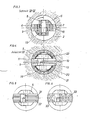
- FIG. 1 and 2 show the implementation of a cased bore, the pivoting jaws being shown in FIG. 1 in the starting position and FIG. 2 in the working position.
- 3 shows a section along line IV-IV of Figure 2
- Figure 4 shows an end view of the jaws in the working position in the direction of arrow III of Figure 2.
- 5 and 6 show an end view of a further embodiment of the drill bit
- FIG. 7 shows an axial section through a further embodiment
- FIG. 8 shows a further axial section through a rotary drill bit according to the invention in the working position.
- 1 represents the tubing with the Schuhkro- J e 20, 2 the borehole wall and 3 the shaft of the drill bit to which the drill pipe or the down-the-hole hammer 19 connects.
- the shoe crown is preferably fitted with cutting tools 22.
- the drill bit 4 has a base body 5, on which two jaws 6 and 7 are articulated by means of a bolt 8. 9 and 10 are the cutting edges, for example made of hard metal, with which the end faces 11 and 12 of the jaws 6 and 7 are fitted.
- the two jaws 6 and 7 are bound together in the pivoted-in starting position by a binding wire 13 which is pulled through holes 14 and 15 of the jaws 6 and 7. In this position, which is shown in FIG. 1, the largest diameter of the jaws is smaller than the inside diameter of the tubing 1, so that the rod assembly with the drill bit 4 can be inserted through the tubing 1.
- the drill bit is designed for percussive and rotating drilling, and the strikes are carried out either by an in-hole hammer or by a hammer acting on the drill pipe.
- the end faces 11 and 12 of the two jaws 6 and 7 are inclined obliquely from the center of the borehole to the edge of the borehole in the direction of advance.
- the centering ring 18 has grooves 21 on the circumference, which allow passage of the cuttings with the flush.
- the body of the bit can be used for multiple sets of jaws or different types of the same.
- two parallel cutting edges 31, 32 are fastened to the base body 5 of the drill bit, and in FIG. 6, warts 33 are used for the cutting body.
- FIG. 7 shows a wear plate 23 arranged between the crown body and the impact surface of the jaws, which prevents damage to the crown body at the point of transmission of the impact on the jaws and can be exchanged together with them.
- One or more mud channels 24 can pass through the body of the crown, thereby improving the removal of the cuttings from the bottom of the borehole.
- Downhole hammers generally have outlet channels for the rinsing air 25 and / or rinsing water 25 '(see FIG. 7) on the underside next to the receiving part for the drill bit.
- flushing bores 24 running through the crown body such that on the one hand they are exactly opposite the outlet opening of the flushing in the hammer and on the other hand open into the front part of the crown body in such a way that an improved flushing effect is achieved than with a pure flow.
- the drill bit according to the invention is designed as a rotary drill bit 28, as shown in FIG. 8, these flushes run ducts 27-27 'from the center 30 of the crown body.
- the jaws are each provided with cutting inserts 26, which have a clearance angle 29 corresponding to the working purpose.
Abstract
Description
Bei der Durchführung von verrohrten Bohrungen in Erdreich oder Gestein mittels eines Bohrgestänges wird die Verrohrung nach Maßgabe des Vortriebes nachgeschoben. Es ist daher erforderlich, die Bohrung mit einem Durchmesser durchzuführen, der zumindest dem Außendurchmesser der Verrohrung entspricht. Hiebei ist es bekannt, die Verrohrung selbst mit einer sogenannten Rohrschuhkrone auszubilden, welche Schneiden trägt. Dies hat aber den Nachteil, daß ein Auswechseln der Rohrschuhkrone nur unter Ziehen der gesamten Verrohrung durchgeführt werden kann. Es ist auch bekannt, exzentrisch verstellbare Bohrkronen zu verwenden, welche durch die Verrohrung hindurchgeführt werden können und dann unterhalb der Verrohrung exzentrisch verstellt werden. Solche Bohrkronen haben den Nachteil eines komplizierten Aufbaues, da die seitliche Verstellung der Bohrkrone durch Rechts-und Linksverdrehung des Gestänges erfolgt. Hiebei besteht auch die Gefahr, daß bei dieser Verdrehung die Schraubverbindungen im Gestänge gelockert oder gelöst werden, in welchem Falle dann die Bohrkrone verlorengehen kann. Es besteht auch der weitere Nachteil, daß große Seitenkräfte von der Bohrkrone auf die Verrohrung ausgeübt werden, wodurch ein großer Verschleiß der Führung der Bohrkrone im Rohr auftritt. Solche Bohrkronen arbeiten drehend und schlagend, wobei für das schlagende Bohren auch ein sogenannter Imlochhammer vorgesehen sein kann.When carrying out cased drilling in soil or rock using a drill pipe, the casing is pushed in according to the advance. It is therefore necessary to drill the hole with a diameter that corresponds at least to the outside diameter of the piping. Hiebei it is known to design the piping itself with a so-called tubular shoe crown, which carries cutting edges. However, this has the disadvantage that the tubular shoe crown can only be replaced by pulling the entire piping. It is also known to use eccentrically adjustable drill bits which can be passed through the tubing and then adjusted eccentrically below the tubing. Such drill bits have the disadvantage of a complicated structure, since the lateral adjustment of the drill bit is carried out by turning the rod to the right and left. There is also the danger that the screw connections in the linkage will be loosened or loosened during this rotation, in which case the drill bit can then be lost. There is also the further disadvantage that large lateral forces are exerted on the casing by the drill bit, as a result of which there is a great deal of wear on the guide of the drill bit in the pipe. Such drill bits work rotating and striking, a so-called down-the-hole hammer can also be provided for the striking drilling.
Die Erfindung bezieht sich nun auf eine an ein Bohrgestänge oder einen Imlochbohrhammer (Tieflochbohrhammer) anschließbare Bohrkrone für die Herstellung von Bohrungen im Erdreich oder Gestein für schlagendes und/oder drehendes Bohren und zielt darauf ab, die geschilderten Nachteile zu vermeiden. Die Erfindung besteht im wesentlichen darin, daß die Bohrkrone einen Grundkörper aufweist, an welchem wenigstens zwei die Arbeitsflächen aufweisenden Backen von einer eingeschwenkten Ausgangsstellung in eine ausgeschwenkte Arbeitsstellung, in welcher die Arbeitsflächen über den größten Durchmesser des Grundkörpers hinausragen, schwenkbar angelenkt sind, wobei in der Ausgangsstellung der Schwerpunkt der Stirnfläche jeder Backe in Achsrichtung gesehen zwischen dem äußeren Rand und der Anlenkachse derselben liegt. Bei der Anwendung der erfindungsgemäßen Bohrkrone für verrohrte Bohrungen wird somit ermöglicht, den Arbeitsdurchmesser der Bohrkrone über den Innendurchmesser der Verrohrung und sogar über den Außendurchmesser derselben hinaus zu vergrößern. In der Ausgangsstellung kann das Gestänge mit der Bohrkrone durch die Verrohrung hindurchgeführt werden und in der Arbeitsstellung kann die Bohrung in einem solchen Durchmesser durchgeführt werden, daß die Verrohrung ohne weiteres nachgeschoben werden kann. Dadurch, daß der Schwerpunkt der Stirnfläche jeder Backe außerhalb der Anlenkachse liegt, werden die Backendurch den auf die Bohrkrone ausgeübten Bohrdruck automatisch in die Arbeitsstellung ausgeschwenkt. Dadurch, daß wenigstens zwei ausschwenkbare Backen vorgesehen sind, wird eine Seitenbeanspruchung der Führung der Bohrkrone in der Verrohrung vermieden oder zumindest vermindert. Die erfindungsgemäße Bohrkrone kann aber auch, für nicht verrohrte Bohrungen verwendet werden, und zwar in Fällen, in welchen es notwendig oder erwünscht ist, den Durchmesser der Bohrung ab einer gewissen Tiefe zu vergrössern. Dies kann beispielsweise bei der Herstellung von Verankerungen der Fall sein, um eine die Verankerungswirkung verbessernde Stufe zu erhalten. In einem solchen Fall wird einfach mit einer üblichen Bohrkrone bis zu der betreffenden Tiefe gebohrt und dann die Bohrarbeit mit der erfindungsgemäßen Bohrkrone festgesetzt. Gemäß einer bevorzugten Ausführungsform der Erfindung sind zwei Backen mittels eines gemeinsamen diametral angeordneten Bolzens an den Grundkörper angelenkt. Die erfindungsgemäße Bohrkrone kann für drehendes Bohren oder für schlagendes Bohren oder für drehendes und schlagendes Bohren verwendet werden. Gemäß einer vorteilhaften Ausführungsform der Erfindung ist die Schwenkbewegung der Backen nach außen durch Anschläge des Grundkörpers begrenzt, gegen welche die Backen in der Arbeitsstellung abgestützt sind. Damit wird der Bohrdurchmesser eindeutig bestimmt. Die Maßnahme, die Backen in der Arbeitsstellung gegen Anschläge des Grundkörpers abzustützen, ist aber im besonderen Maße für schlagendes Bohren vorteilhaft, da auf diese Weise die Schlagkräfte über die Anschläge unmittelbar in die Backen eingeleitet werden, ohne daß die Schwenklagerung derselben beansprucht wird. Die Schlagkräfte können hiebei in bekannter Weise durch einen Imlochhammer oder bei kurzem Bohrgestänge unmittelbar auf das Bohrgestänge ausgeübt werden.The invention now relates to a drill bit that can be connected to a drill pipe or a down-the-hole hammer (deep hole hammer drill) for the production of holes in the ground or rock for percussive and / or rotating drilling and aims to avoid the disadvantages described. The invention consists essentially in the fact that the drill bit has a base body on which at least two jaws having the work surfaces are pivotably articulated from a pivoted-in starting position into a pivoted-out work position in which the work surfaces protrude beyond the largest diameter of the base body, in which Starting position, the center of gravity of the end face of each jaw, viewed in the axial direction, lies between the outer edge and the articulation axis thereof. When using the drill bit according to the invention for cased bores, it is thus possible to enlarge the working diameter of the drill bit beyond the inner diameter of the casing and even beyond the outside diameter thereof. In the starting position, the rod with the drill bit can be passed through the piping and in the working position, the drilling can be carried out in such a diameter that the piping can be easily pushed on. Because the center of gravity of the end face of each jaw lies outside the articulation axis, the jaws are automatically pivoted into the working position by the drilling pressure exerted on the drill bit. The fact that at least two swiveling jaws are provided prevents or at least reduces side stress on the guide of the drill bit in the piping. However, the drill bit according to the invention can also be used for non-cased bores, in cases in which it is necessary or desirable to enlarge the diameter of the bore from a certain depth. This can be the case, for example, in the manufacture of anchors in order to obtain a step which improves the anchoring effect. In such a case, it is simply drilled to the relevant depth with a conventional drill bit and then the drilling work is fixed with the drill bit according to the invention. According to a preferred Aus In the embodiment of the invention, two jaws are articulated to the base body by means of a common, diametrically arranged bolt. The drill bit according to the invention can be used for rotary drilling or for percussion drilling or for rotary and percussion drilling. According to an advantageous embodiment of the invention, the pivoting movement of the jaws to the outside is limited by stops of the base body against which the jaws are supported in the working position. The bore diameter is thus clearly determined. The measure of supporting the jaws in the working position against stops of the base body is particularly advantageous for impact drilling, since in this way the impact forces are introduced directly into the jaws via the stops without the pivot bearing of the same being stressed. The impact forces can be exerted directly on the drill pipe in a known manner by means of an in-hole hammer or, in the case of a short drill pipe.
Vorzugsweise sind in der Ausgangsstellung die Stirnflächen der Backen von der Bohrkronenmitte zum Rand derselben in Vortriebsrichtung geneigt. Auf diese Weise wird die Spreizbewegung von der Ausgangsstellung in die Arbeitsstellung begünstigt und mit Sicherheit eingeleitet.In the starting position, the end faces of the jaws are preferably inclined from the center of the drill bit to the edge thereof in the direction of advance. In this way, the spreading movement from the starting position into the working position is favored and initiated with certainty.
Gemäß der Erfindung ist die Anordnung zweckmäßig so getroffen, daß in der Arbeitsstellung die stirnseitige Arbeitsfläche wenigstens eines Backens sich über die Bohrkronenachse erstreckt. Durch diese Ausbildung wird erreicht, daß auch das Bohrlochzentrum zerspant wird.According to the invention, the arrangement is expediently such that in the working position the front working surface of at least one jaw extends over the drill bit axis. This configuration ensures that the borehole center is also machined.
Vorzugsweise ist die Ausbildung so getroffen, daß die Backen in der Ausgangsstellung durch eine Kraft gehalten sind, welche geringer ist als die im Betrieb auftretende Spreizkraft. Auf diese Weise sind die Backen beim Einführen durch die Verrohrung oder durch ein Bohrloch von kleinerem Durchmesser hindurch in der Ausgangsstellung gesichert, so daß ein Hängenbleiben an Rohrschüssen oder an der rauhen Bohrlochwandung vermieden wird. Diese Sicherung kann in einfacher Weise durch einen Bindedraht erreicht werden, der bei der Bohrbeanspruchung bricht, und es können daher gemäß der Erfindung die Backe Querbohrungen für einen Bindedraht aufweisen.The design is preferably such that the jaws are held in the starting position by a force which is less than the spreading force occurring during operation. In this way, the jaws are secured in the starting position when inserted through the piping or through a borehole of smaller diameter, so that sticking to pipe sections or to the rough borehole wall is avoided. This backup can be achieved in a simple manner by means of a binding wire which breaks under drilling stress, and the jaws can therefore have transverse holes for a binding wire according to the invention.
Der größte Durchmesser der Backen in der Arbeitsstellung bestimmt den Durchmesser der herzustellenden Bohrung und der größte Durchmesser der Backen in der Ausgangsstellung bzw. der größte Durchmesser des Grundkörpers ist maßgebend für das Einführen des Bohrgestänges mit der Bohrkrone in eine Verrohrung oder in eine Bohrung. Gemäß der Erfindung kann ohne weiteres der größte Durchmesser der Backen in der Arbeitsstellung um 15 % bis 30 %, vorzugsweise bis zu 35 %, größer sein als der größte Durchmesser der Backen in der Ausgangsstellung bzw. der größte Durchmesser des Grundkörpers. Für die Herstellung von verrohrten Bohrungen ist hiebei der größte Durchmesser der Backen in der Ausgangsstellung kleiner als der Führungsdurchmesser der Bohrkrone in der Verrohrung.The largest diameter of the jaws in the working position determines the diameter of the bore to be produced and the largest diameter of the jaws in the starting position or the largest diameter of the base body is decisive for the insertion of the drill pipe with the drill bit into a piping or into a bore. According to the invention, the largest diameter of the jaws in the working position can easily be 15% to 30%, preferably up to 35% larger than the largest diameter of the jaws in the starting position or the largest diameter of the base body. For the production of cased bores, the largest diameter of the jaws in the starting position is smaller than the guide diameter of the drill bit in the casing.
Die Arbeitsflächen der Backen können in bekannter Weise mit einer oder mehreren Reihen von Schneiden oder Warzen bestückt oder ausgebildet sein.The work surfaces of the jaws can be equipped or designed in a known manner with one or more rows of cutting edges or warts.
In der Zeichnung ist die Erfindung anhand eines Ausführungsbeispieles schematisch erläutert.In the drawing, the invention is explained schematically using an exemplary embodiment.
Fig.1 und 2 zeigen die Durchführung einer verrohrten Bohrung, wobei die schwenkbaren Backen in Fig.1 in der Ausgangsstellung und Fig.2 in der Arbeitsstellung dargestellt sind. Fig.3 zeigt einen Schnitt nach Linie IV-IV der Fig.2, Fig.4 zeigt eine Stirnansicht der Backen in der Arbeitsstellung in Richtung des Pfeiles III der Fig.2. Fig.5 und 6 zeigen eine Stirnansicht einer weiteren Ausführungsform der Bohrkrone, Fig.7 zeigt einen Axialschnitt durch eine weitere Ausführungsform und Fig.8 einen weiteren Axialschnitt durch eine erfindungsgemäße Drehbohrkrone in der Arbeitsstellung.1 and 2 show the implementation of a cased bore, the pivoting jaws being shown in FIG. 1 in the starting position and FIG. 2 in the working position. 3 shows a section along line IV-IV of Figure 2, Figure 4 shows an end view of the jaws in the working position in the direction of arrow III of Figure 2. 5 and 6 show an end view of a further embodiment of the drill bit, FIG. 7 shows an axial section through a further embodiment and FIG. 8 shows a further axial section through a rotary drill bit according to the invention in the working position.
In Fig.1 und 2 stellt 1 die Verrohrung mit der Schuhkro- Je 20, 2 die Bohrlochwand und 3 den Schaft der Bohrkrone dar, an welchen das Bohrgestänge oder der Imlochhammer 19 anschließt. Die Schuhkrone ist vorzugsweise mit Schneidwerkzeugen 22 besetzt. Die Bohrkrone 4 weist einen Grundkörper 5 auf, an welchen zwei Backen 6 und 7 mittels eines Bolzens 8 angelenkt sind. 9 und 10 sind die beispielsweise aus Hartmetall bestehenden Schneiden, mit welchen die Stirnflächen 11 und 12 der Backen 6 und 7 bestückt sind. Durch einen Bindedraht 13, welcher durch Löcher 14 und 15 der Backen 6 und 7 hindurchgezogen ist, sind die beiden Backen 6 und 7 in der eingeschwenkten Ausgangsstellung zusammengebunden. In dieser Stellung, welche ih Fig.1 dargestellt ist, ist der größte Durchmesser der Backen kleiner als der Innendurchmesser der Verrohrung 1, so daß das Gestänge mit der Bohrkrone 4 durch die Verrohrung 1 hindurch eingeführt werden kann.In FIGS. 1 and 2, 1 represents the tubing with the Schuhkro- J
Sobald die Bohrkrone 4 ihre Stellung unterhalb der Verrohrung 1 erreicht hat, kann der Bohrvorgang beginnen. Die Bohrkrone ist für schlagendes und drehendes Bohren ausgebildet und die Schläge werden entweder durch einen Imlochhammer oder durch einen auf das Bohrgestänge wirkenden Hammer ausgeübt.As soon as the
Die Stirnflächen 11 und 12 der beiden Backen 6 und 7 sind schräg von der Bohrlochmitte zum Bohrlochrand in Vortriebsrichtung- geneigt. Bei den ersten Schlägen entsteht bereits eine Radialkomponente der Kräfte, der Bindedraht 13 wird abgerissen und die Backen 6 und 7 gelangen in die in Fig.2 dargestellte Arbeitsstellung. In dieser Arbeitsstellung, in welcher der Durchmesser der Backen den Außendurchmesser der Verrohrung 1 bzw. der Schuhkrone 20 überschreitet, sind die Backen gegen Anschläge 16 und 17 des Grundkörpers 5 abgestützt, so daß die Schläge unmittelbar auf die Backen wirken und der Bolzen 8 entlastet ist. Da die Backen 6 und 7 nach beiden Seiten auseinandergespreizt werden, entstehen keine oder nur geringe Seitenkräfte, so daß die Führung der Bohrkrone 4, welche durch einen Zentrierring 18 am Unterteil des Bohrhammers 19 gegeben ist, weitgehend entlastet und daher nur geringem Verschleiß ausgesetzt ist.The end faces 11 and 12 of the two
Der Zentrierring 18 besitzt am Umfang Nuten 21, die den Durchtritt des Bohrkleins mit der Spülung gestatten.The
Durch eine Sicherung, z.B. einen Spannstift 19, ist der Bolzen 8 gegen axiale Verschiebung gesichert.With a backup, e.g. a
Da die Schneidbacken der Bohrkrone auswechselbar sind, kann der Körper der Krone für mehrere Sätze von Backen oder verschiedene Typen derselben verwendet werden. In Fig.5 sind zwei parallele Schneiden 31, 32 am Grundkörper 5 der Bohrkrone befestigt und in Fig.6 sind Warzen 33 für den Schneidkörper verwendet.Because the cutting bits of the drill bit are interchangeable, the body of the bit can be used for multiple sets of jaws or different types of the same. In FIG. 5, two
Fig. 7 zeigt eine zwischen Kronenkörper und Aufschlagfläche der Backen angeordnete Verschleißplatte 23, welche Beschädigungen des Kronenkörpers an der übertragungsstelle des Schlages auf die Backen verhindert und gemeinsam mit diesen ausgetauscht werden kann. Durch den Körper der Krone können ein oder mehrere Spülungskanäle 24 verlaufen, wodurch die Abförderung des Bohrkleins von der Bohrlochsohle verbessert wird. Imlochhämmer weisen im allgemeinen an der Unterseite neben dem Aufnahmeteil für die Bohrkrone liegende Austrittskanäle für die Spülluft 25 und/oder Spülwasser 25' (siehe Fig.7) auf. Es kann daher zweckmäßig sein, durch den Kronenkörper verlaufende Spülungsbohrungen 24 so anzuordnen, daß sie einerseits der Austrittsöffnung der Spülung im Hammer genau gegenüberliegen und anderseits im Vorderteil des Kronenkörpers so münden, daß eine verbesserte Spülungswirkung erzielt wird, als bei einer reinen Umströmung.FIG. 7 shows a
Bei Ausführung der erfindungsgemäßen Bohrkrone als Drehbohrkrone 28, wie in Fig.8 gezeigt, verlaufen diese Spülungskanäle 27-27' von der Mitte 30 des Kronenkörpers aus. Bei dieser Drehbohrkrone 28 sind die Backen jeweils mit Schneideinsätzen 26 versehen, welche einen dem Arbeitszweck entsprechenden Freiwinkel 29 aufweisen.When the drill bit according to the invention is designed as a
Claims (12)
dadurch gekennzeichnet,
daß sie einen Grundkörper (5) aufweist, an welchem wenigstens zwei die Arbeitsflächen (9, 10) aufweisende Backen (6, 7) von einer eingeschwenkten Ausgangsstellung in eine ausgeschwenkte Arbeitsstellung, in welcher die Arbeitsflächen (9, 10) über den größten Durchmesser des Grundkörpers (5) hinausragen, schwenkbar angelenkt sind, wobei in der Ausgangsstellung der Schwerpunkt der Stirnfläche (11, 12) jeder Backe in Achsrichtung gesehen zwischen dem äußeren Rand und der Anlenkachse derselben liegt.1 to a drill string or a Imlochbohrhammer (low 'hole hammer drill) connectable drill bit for the production of holes in soil or rock for percussive and / or rotary drilling,
characterized,
that it has a base body (5), on which at least two the work surfaces (9, 10) have jaws (6, 7) from a swung-in starting position into a swiveled-out working position, in which the work surfaces (9, 10) have the largest diameter of the Protrude base body (5), are pivotally articulated, the center of gravity of the end face (11, 12) of each jaw lying in the axial direction between the outer edge and the articulation axis thereof in the starting position.
dadurch gekennzeichnet,
daß zwei Backen (6, 7) mittels eines gemeinsamen diametral angeordneten Bolzens (8) an den Grundkörper (5) angelenkt sind.2. drill bit according to claim 1,
characterized,
that two jaws (6, 7) are articulated to the base body (5) by means of a common diametrically arranged bolt (8).
dadurch gekennzeichnet,
daß die Schwenkbewegung der Backen (6, 7) nach außen durch vorzugsweise in Form einer auswechselbaren Verschleißplatte(23) ausgebildeten Anschläge (16, 17) des Grundkörpers (5) begrenzt ist, gegen welche die Backen (6, 7) in Arbeitsstellung abgestützt sind (Fig.7).3. drill bit according to claim 1 or 2,
characterized,
that the pivoting movement of the jaws (6, 7) to the outside is limited by stops (16, 17) of the base body (5) which are preferably in the form of an exchangeable wear plate (23), against which the jaws (6, 7) are supported in the working position (Fig.7).
dadurch gekennzeichnet,
daß in der Ausgangsstellung die Stirnflächen (11, 12) der Backen (6, 7) von der Bohrkronenmitte zum Rand derselben in Vortriebsrichtung geneigt sind.4. drill bit according to claim 1, 2 or 3,
characterized,
that in the starting position the end faces (11, 12) of the jaws (6, 7) are inclined from the center of the drill bit to the edge thereof in the direction of advance.
dadurch gekennzeichnet,
daß in der Arbeitsstellung die stirnseitige Arbeitsfläche (10) wenigstens eines Backens (7) sich über die Bohrkronenachse erstreckt.5. drill bit according to one of claims 1 to 4,
characterized,
that in the working position the front working surface (10) of at least one jaw (7) extends over the drill bit axis.
dadurch gekennzeichnet,
daß die Backen (6, 7) in der Ausgangsstellung durch eine Kraft gehalten sind, welche geringer ist als die im Betrieb auftretende Spreizkraft.6. drill bit according to one of claims 1 to 5,
characterized,
that the jaws (6, 7) are held in the starting position by a force which is less than the spreading force occurring during operation.
dadurch gekennzeichnet,
daß die Backen (6, 7) Querbohrungen (14, 15) für einen Bindedraht (13) aufweisen.7. drill bit according to claim 6,
characterized,
that the jaws (6, 7) have transverse bores (14, 15) for a binding wire (13).
dadurch gekennzeichnet,
daß der größte Durchmesser der Backen (6, 7) in der Arbeitsstellung um 15 % bis 30 %, vorzugsweise bis zu 35 %, größer ist als der größte Durchmesser des Backens in der Ausgangsstellung bzw. der größte Durchmesser des Grundkörpers (5).8. drill bit according to one of claims 1 to 7,
characterized,
that the largest diameter of the jaws (6, 7) in the working position is 15% to 30%, preferably up to 35%, larger than the largest diameter of the jaw in the starting position or the largest diameter of the base body (5).
dadurch gekennzeichnet,
daß der größte Durchmesser der Backen (6, 7) in der Ausgangsstellung kleiner ist als der Führungsdurchmesser der Bohrkrone (4) in der Verrohrung.9. Drill bit according to one of claims 1 to 8, for the production of cased bores,
characterized,
that the largest diameter of the jaws (6, 7) in the starting position is smaller than the guide diameter of the drill bit (4) in the piping.
dadurch gekennzeichnet,
daß die Backen (6, 7) mit einer oder mehreren Reihen von Meißelschneiden (31., 32) (Fig.5), Bohrschneiden (26) (Fig.6) oder Warzen (33) versehen sind.10. drill bit according to one of claims 1 to 9,
characterized,
that the jaws (6, 7) are provided with one or more rows of chisel cutting edges (31, 32) (Fig.5), drilling cutting edges (26) (Fig.6) or warts (33).
daß bei drehendem Bohren ein im wesentlichen zentrisch angeordneter Spülungskanal (30) zum Durchtritt der Bohrspülung aus dem Gestänge zum Bohrlochtiefsten vorgesehen ist (Fig.8).11. Drill bit according to one of claims 1 to 10, characterized,
that when drilling rotates an essentially centrally located flushing channel (30) is provided for the passage of the drilling fluid out of the rod to the deepest hole (FIG. 8).
Applications Claiming Priority (2)
| Application Number | Priority Date | Filing Date | Title |
|---|---|---|---|
| AT2435/78 | 1978-04-06 | ||
| AT243578A AT354960B (en) | 1978-04-06 | 1978-04-06 | DRILL BIT FOR THE PRODUCTION OF DRILLS IN GROUND OR STONE |
Publications (2)
| Publication Number | Publication Date |
|---|---|
| EP0004674A2 true EP0004674A2 (en) | 1979-10-17 |
| EP0004674A3 EP0004674A3 (en) | 1979-10-31 |
Family
ID=3534299
Family Applications (1)
| Application Number | Title | Priority Date | Filing Date |
|---|---|---|---|
| EP79101061A Withdrawn EP0004674A3 (en) | 1978-04-06 | 1979-04-06 | Drill bit for making bore holes in earth and rock |
Country Status (2)
| Country | Link |
|---|---|
| EP (1) | EP0004674A3 (en) |
| AT (1) | AT354960B (en) |
Cited By (1)
| Publication number | Priority date | Publication date | Assignee | Title |
|---|---|---|---|---|
| EP0358786A1 (en) * | 1988-09-13 | 1990-03-21 | Ing. G. Klemm Bohrtechnik GmbH | Superimposing drilling device |
Families Citing this family (1)
| Publication number | Priority date | Publication date | Assignee | Title |
|---|---|---|---|---|
| DE102014104516A1 (en) * | 2014-03-31 | 2015-10-01 | Sysbohr Gmbh - Bohrtechnik Für Den Spezialtiefbau | Drill bit, in particular for overburden drilling, and drilling device with a drill bit |
Citations (12)
| Publication number | Priority date | Publication date | Assignee | Title |
|---|---|---|---|---|
| DE39674C (en) * | A. FAUCK und E. HASENÖRL in Wien | Free fall drill for deep drilling | ||
| DE3971C (en) * | H. GÖTZE, Schlossermeister, in Neumünster in Holstein | Earth auger | ||
| FR505941A (en) * | 1918-11-12 | 1920-08-10 | Chas L Stickney | Improvements to drilling rigs |
| US1428774A (en) * | 1921-09-19 | 1922-09-12 | William R Gardner | Fishtail bit |
| GB297285A (en) * | 1928-03-02 | 1928-09-20 | Colon Dev Co | Improvements in well-boring apparatus |
| US1733452A (en) * | 1926-12-13 | 1929-10-29 | John W Doody | Underreamer |
| GB540027A (en) * | 1940-04-26 | 1941-10-02 | Percy Cox | Improvements in and relating to rock boring and like tools |
| US2397652A (en) * | 1944-02-03 | 1946-04-02 | Jr Woyman B Dunlap | Underreamer |
| DE830033C (en) * | 1950-01-15 | 1952-01-31 | Guenther Fluegge Dr Ing | Drill bits |
| US2599167A (en) * | 1946-02-23 | 1952-06-03 | Dionisotti Joseph | Scraping out device for mining boreholes |
| FR2171290A1 (en) * | 1972-02-10 | 1973-09-21 | Atlas Copco Ab | |
| FR2274780A1 (en) * | 1974-06-12 | 1976-01-09 | Ugine Aciers | BUTTON SIZES FOR ROCK PERFORATION USING A HAMMER BOTTOM OF SIDE BLOWING HOLE |
-
1978
- 1978-04-06 AT AT243578A patent/AT354960B/en not_active IP Right Cessation
-
1979
- 1979-04-06 EP EP79101061A patent/EP0004674A3/en not_active Withdrawn
Patent Citations (12)
| Publication number | Priority date | Publication date | Assignee | Title |
|---|---|---|---|---|
| DE39674C (en) * | A. FAUCK und E. HASENÖRL in Wien | Free fall drill for deep drilling | ||
| DE3971C (en) * | H. GÖTZE, Schlossermeister, in Neumünster in Holstein | Earth auger | ||
| FR505941A (en) * | 1918-11-12 | 1920-08-10 | Chas L Stickney | Improvements to drilling rigs |
| US1428774A (en) * | 1921-09-19 | 1922-09-12 | William R Gardner | Fishtail bit |
| US1733452A (en) * | 1926-12-13 | 1929-10-29 | John W Doody | Underreamer |
| GB297285A (en) * | 1928-03-02 | 1928-09-20 | Colon Dev Co | Improvements in well-boring apparatus |
| GB540027A (en) * | 1940-04-26 | 1941-10-02 | Percy Cox | Improvements in and relating to rock boring and like tools |
| US2397652A (en) * | 1944-02-03 | 1946-04-02 | Jr Woyman B Dunlap | Underreamer |
| US2599167A (en) * | 1946-02-23 | 1952-06-03 | Dionisotti Joseph | Scraping out device for mining boreholes |
| DE830033C (en) * | 1950-01-15 | 1952-01-31 | Guenther Fluegge Dr Ing | Drill bits |
| FR2171290A1 (en) * | 1972-02-10 | 1973-09-21 | Atlas Copco Ab | |
| FR2274780A1 (en) * | 1974-06-12 | 1976-01-09 | Ugine Aciers | BUTTON SIZES FOR ROCK PERFORATION USING A HAMMER BOTTOM OF SIDE BLOWING HOLE |
Cited By (1)
| Publication number | Priority date | Publication date | Assignee | Title |
|---|---|---|---|---|
| EP0358786A1 (en) * | 1988-09-13 | 1990-03-21 | Ing. G. Klemm Bohrtechnik GmbH | Superimposing drilling device |
Also Published As
| Publication number | Publication date |
|---|---|
| AT354960B (en) | 1980-02-11 |
| EP0004674A3 (en) | 1979-10-31 |
| ATA243578A (en) | 1979-07-15 |
Similar Documents
| Publication | Publication Date | Title |
|---|---|---|
| DE60117372T2 (en) | DEVICE AND METHOD FOR PRODUCING LATERAL DRILLING | |
| DE69815255T2 (en) | Rotary drill bit for milling borehole piping and for drilling an underground formation | |
| DE60127112T2 (en) | EXPANDABLE CHISEL | |
| DE3633749A1 (en) | COMPRESSED AIR PERFORMANCE AND DEVICE THEREFOR | |
| DE3114612A1 (en) | IN A HARD ROCK, ESPECIALLY ROCKS, DRILLING HOLE PRESSABLE TO BE DRIVEN AND METHOD FOR PRODUCING A HOLE | |
| DE3503893C1 (en) | Drilling device | |
| DE3014990A1 (en) | EARTH DRILLING DEVICE | |
| DE2701044A1 (en) | EARTH DRILLING JIG | |
| DE2839868A1 (en) | DRILL BIT | |
| DE4432710C1 (en) | Underground horizon boring tool with directional control | |
| DE1235241B (en) | Drilling device with several deep hole hammer drills arranged in parallel to enlarge the hole | |
| DE3939538C2 (en) | ||
| DE19652530A1 (en) | Downhole hammer | |
| DE2758385C3 (en) | Impact drilling device for large holes | |
| EP0004674A2 (en) | Drill bit for making bore holes in earth and rock | |
| DE3109367C2 (en) | Drilling tool for deep hole hammers | |
| DE60117234T2 (en) | Method for drilling a borehole using a bicentric drill bit | |
| DE4116771C2 (en) | Device for making earth bores | |
| DE1188014B (en) | Rock drill with eccentric drilling tool | |
| EP2094933B1 (en) | Device for percussion drilling or rotary percussion drilling in rocky material | |
| DE3024102A1 (en) | Eccentric overburden drill bit - with lever on inner drill tube urging bit crown outside outer tube | |
| DE102005046495B4 (en) | Drilling device for creating cased boreholes | |
| DE3024218C2 (en) | Impact drilling devices for large holes | |
| EP0358786A1 (en) | Superimposing drilling device | |
| DE758462C (en) | Rock percussion drill |
Legal Events
| Date | Code | Title | Description |
|---|---|---|---|
| PUAI | Public reference made under article 153(3) epc to a published international application that has entered the european phase |
Free format text: ORIGINAL CODE: 0009012 |
|
| PUAL | Search report despatched |
Free format text: ORIGINAL CODE: 0009013 |
|
| AK | Designated contracting states |
Designated state(s): BE CH DE FR GB IT LU NL SE |
|
| AK | Designated contracting states |
Designated state(s): BE CH DE FR GB IT LU NL SE |
|
| 17P | Request for examination filed | ||
| STAA | Information on the status of an ep patent application or granted ep patent |
Free format text: STATUS: THE APPLICATION HAS BEEN WITHDRAWN |
|
| 18W | Application withdrawn |
Withdrawal date: 19810205 |
|
| RIN1 | Information on inventor provided before grant (corrected) |
Inventor name: SULZER,JOSEF |