EP0002823B1 - Echangeur de chaleur à faisceau tubulaire et procédé de fabrication - Google Patents
Echangeur de chaleur à faisceau tubulaire et procédé de fabrication Download PDFInfo
- Publication number
- EP0002823B1 EP0002823B1 EP78101829A EP78101829A EP0002823B1 EP 0002823 B1 EP0002823 B1 EP 0002823B1 EP 78101829 A EP78101829 A EP 78101829A EP 78101829 A EP78101829 A EP 78101829A EP 0002823 B1 EP0002823 B1 EP 0002823B1
- Authority
- EP
- European Patent Office
- Prior art keywords
- rods
- tubes
- region
- tube
- outer rings
- Prior art date
- Legal status (The legal status is an assumption and is not a legal conclusion. Google has not performed a legal analysis and makes no representation as to the accuracy of the status listed.)
- Expired
Links
Images


Classifications
-
- F—MECHANICAL ENGINEERING; LIGHTING; HEATING; WEAPONS; BLASTING
- F28—HEAT EXCHANGE IN GENERAL
- F28F—DETAILS OF HEAT-EXCHANGE AND HEAT-TRANSFER APPARATUS, OF GENERAL APPLICATION
- F28F9/00—Casings; Header boxes; Auxiliary supports for elements; Auxiliary members within casings
- F28F9/007—Auxiliary supports for elements
- F28F9/013—Auxiliary supports for elements for tubes or tube-assemblies
- F28F9/0132—Auxiliary supports for elements for tubes or tube-assemblies formed by slats, tie-rods, articulated or expandable rods
-
- F—MECHANICAL ENGINEERING; LIGHTING; HEATING; WEAPONS; BLASTING
- F28—HEAT EXCHANGE IN GENERAL
- F28D—HEAT-EXCHANGE APPARATUS, NOT PROVIDED FOR IN ANOTHER SUBCLASS, IN WHICH THE HEAT-EXCHANGE MEDIA DO NOT COME INTO DIRECT CONTACT
- F28D7/00—Heat-exchange apparatus having stationary tubular conduit assemblies for both heat-exchange media, the media being in contact with different sides of a conduit wall
- F28D7/16—Heat-exchange apparatus having stationary tubular conduit assemblies for both heat-exchange media, the media being in contact with different sides of a conduit wall the conduits being arranged in parallel spaced relation
Definitions
- the present invention relates generally to heat exchangers and to methods of heat exchanger construction.
- Heat transfer is an important part of any process.
- an indirect transfer of heat from one medium to another is usually accomplished by the use of heat exchangers of which there are many types.
- heat exchangers of which there are many types.
- the art of heat exchanger design is developed to a very high degree.
- there is still room for improvement in a number of areas such as reducing pressure drop, increasing overall heat transfer co-efficients, reducing fouling, and in heat exchangers utilizing a tube bundle, such as the shell and tube heat exchangers, improving the tube support and ease of assembly.
- the tubes in a shell and tube heat exchanger prematurely fail because the tubes vibrate or rub against one another or other parts of the heat exchanger such as for example, a baffle or the shell.
- the tubes and the rods are designed with slightly smaller dimensions to facilitate the complete assembly of the tube bundle, then the tubes will not be tight in the baffles and will be subject to vibration-induced wear during operation which can result in tube damage and premature failure of the heat exchanger.
- a heat exchanger structure is provided by utilizing at least one baffle support in the tube bundle intermediate the opposite ends of the tubes which permits loose passage of the tubes therethrough during assembly of the tube bundle and subsequently permits firm engagement of these tubes when the tubes are properly positioned.
- An object of the present invention is to provide improved support for tubes of a tube bundle.
- Another object of the present invention is to provide an improved method of assembly of the support rods in a tube bundle of a heat exchanger.
- Yet another object of the present invention is to provide improved reliability in a shell and tube heat exchanger.
- Still another object of the present invention is to facilitate the construction of heat exchangers.
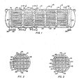
- the heat exchanger 10 comprises a shell 12 and a tube bundle 14 positioned therein.
- the tube bundle 14 includes a pair of tube sheets 16 and 18 having apertures formed therein through which the opposite ends of a plurality of tubes 20 extend. The opposite ends of the tubes are secured to the respective tube sheets to provide support for the plurality of parallel aligned tubes 20.
- a pair of baffles 22 and a second pair of baffles 24 are positioned alternately along the longitudinal axes of the parallel tubes 20 in spaced relation and provide support for the tubes intermediate the tube sheets 16 and 18.
- baffles 22 and 24 are shown lying in a plane normal to the longitudinal axis of the tubes 20 of the tube bundle 14, it is possible to use baffles which are not in planes perpendicular or normal to the longitudinal axis of the tube bundle, however, baffles lying in perpendicular or normal planes as shown are more easily and economically constructed and are thus preferred.
- Nozzles 26 and 28 communicate with the respective opposite ends of the tube side of the heat exchanger 10 providing means for passing a first fluid through the tubes.
- Nozzles 30 and 32 communicate with the respective ends of the shell side of the heat exchanger 10 and provide means for passing a second fluid over the outside surfaces of the tubes when preferably using countercurrent flow of the heat exchange fluids or mediums.
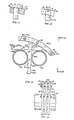
- the tubes 20 in the heat exchanger 10 are laid out in a square pitch, and generally a square pitch tube layout provides greater surface area for a given shell diameter for an apparatus constructed in accordance with the present invention.
- This layout of the tubes 20 is best illustrated in FIGS 2 and 3. It will be seen that the tubes 20 thus laid out form a plurality of vertically spaced horizontal tube rows and a plurality of horizontally spaced vertical tube rows.
- the baffles 22 illustrated in FIG. 2 comprise a baffle or supporting ring 34 encircling the tubes 20.
- a plurality of horizontally extending baffle rods or bars 36 are fixedly secured at their opposite ends in the supporting ring 34 and extend between alternate pairs of horizontal parallel tube rows.
- a plurality of vertically extending baffle rods or bars 38 are fixedly secured at their opposite ends in the supporting outer ring 34 and extend between alternate pairs of vertical parallel tube rows.
- the opposite ends of the rods 36 and 38 may be suitably secured to the outer ring 34 by welding as shown in either FIG. 11 or FIG. 12, or may be belted thereto as illustrated in FIGS. 13 and 14.
- the construction of the baffle 24 is illustrated in FIG. 3.
- the baffle 24 comprises an outer supporting baffle ring 40 which encircles the tubes 20 in a manner similar to that described for the ring 34.
- a plurality of horizontally extending baffle rods or bars 42 are movably secured at their opposite ends in the outer ring 40 and extend between alternate pairs of horizontal parallel tube rows. It will be noted, however, that the tube rows between which the rods 42 extend are not the tube rows between which the rods 36 of the baffle 22 extend.
- the rods 42 are positioned between horizontal tube rows which are open or unbaffled in the baffle 22.
- the baffle 24 includes a plurality of vertically extending baffle rods or bars 44 movably secured at their opposite ends in the supporting outer ring 40 which rods extend between alternate pairs of vertical parallel tube rows.
- the rods 44 are not positioned between the same vertical tube rows ' through which the baffle rods 38 of the baffle 22 extend, but rather extend between adjacent vertical tube rows which are open in the baffle 22.
- the rods 36 and 38 of the baffles 22 are of such thickness or diameter as to be closely received between the tubes of the adjacent horizontal and vertical tube rows, respectively. As best shown in FIGS. 4 and 5, the opposite ends of the rods 42 and 44 are slidably received within corresponding apertures 46 and 48 extending through the outer ring 40.
- Each of the rods 42 and 44 includes a plurality of first regions 50 of reduced thickness spaced along the length of the respective rod in correspondence to the center to center distance between the tubes 20 of adjacent tube rows.
- the regions 50 of reduced thickness may be circular in cross-section as illustrated in FIGS. 4 and 5 and as further illustrated in FIG. 10, or otherwise shaped.
- Each region 50 of reduced thickness is preferably approximately 1/16-inch (1.5875 mm) less in thickness than the space between adjacent tubes in the tube row separated by the baffle rod.
- the baffle rods 42 and 44 further include second regions 52 of increased thickness disposed adjacent the first regions 50 of reduced thickness. These regions 52 of increased thickness may be of either circular or rectangular cross-section. The thickness of the second regions 52 is preferably slightly greater than the nominal distance between adjacent tubes of the tube rows separated by the respective baffle rods.
- FIG. 10 illustrates an enlarged portion of a baffle rod or bar 42 illustrating the region 50 of reduced thickness and the region 52 of increased thickness thereon.
- the rod illustrated in FIG. 10 is preferably circular in cross-section throughout its entire length.
- the first region 50 of reduced thickness is arcuately shaped along the longitudinal axis of the rod, and conforms generally to the configuration of the outer surface of the tubes 20. It will be noted that the arcuate shape of the region 50 of reduced thickness provides a third transitional region 54 formed on the surface of the rod extending between the first and second regions 50 and 52 and increasing in circular cross-sectional area between the first and second regions.
- FIGS. 8 and 9 illustrate a slightly modified version of the rod or bar of FIG. 10 which will be designated by the reference character 42a.
- the first regions 50 of reduced thickness and the second regions 52 of increased thickness are of circular cross-section as in the rod 42.
- the third transitional region 54a interconnecting each of the first and second regions 50 and 52 provides a frusto- conically shaped surface on the rod 42a increasing in circular cross-section from each, first region 50 to each corresponding second region 52.
- This configuration of the third transitional region 54a provides a more gradual transition between each region of reduced thickness and the corresponding region of increased thickness.
- FIGS. 6 and 7 illustrate a third form of baffle rod or bar of substantially rectangular cross-section which is designated by the reference character 42b.
- the first regions of reduced thickness of the rod 42b are designated by the reference character 50b, and the second regions of increased thickness are designated by the reference character 52b.
- Each region 50b of reduced thickness is connected to a corresponding region 52b of increased thickness by a third transitional region 54b formed on the surface of the rod of increasing rectangular cross-sectional area from the region of reduced thickness to the region of increased thickness.
- FIGS. 13 and 14 illustrate the connections of the baffle rod or bar 42b and a similarly constructed vertical baffle rod or bar 44b to a modified outer supporting ring designated by the reference character 40b.
- the outer ring 40b comprises a central ring member 56 and a pair of external ring members 58 and 60 which cooperate with threaded bolts 62 to fixedly secure the outer ends of the rods 42b and 44b to the outer ring 40b.
- the rods 36, 38, 42 and 44 can be constructed of round or square tubing material and the regions 50 of reduced thickness between the regions 52 of increased thickness can be advantageously and economically formed by stamping whereby the regions of reduced thickness are substantially flat at their midpoints between adjacent regions of increased thickness.
- Such flat regions of reduced thickness are preferably oriented with the major axis thereof in alignment with the longitudinal axes of the tubes to thereby present a minimum cross-sectional area to the flow of fluid around the baffle rods and reduce the pressure drop of the flowing fluid across the rods.
- the tubes 20 are inserted through the baffles 22 and 24 which are spaced apart as illustrated in FIG. 1.
- the rods 42 and 44 of the baffles 24 are movably supported by the respective supporting rings 40 in the position illustrated in FIG. 4 thereby permitting the free passage of the tubes 20 through the baffles 22 and 24.
- the ends of the tubes 20 are then received through the corresponding apertures 64 formed in the tube sheets 16 and 18.
- the tubes 20 are fixedly secured to the tube sheets 16 and 18 with the end of each tube forming a fluid tight seal with the corresponding aperture in the tube sheet.
- the rods 42 and 44 of the baffles 24 are then driven or otherwise moved from their first positions as illustrated in FIG. 4 to their second positions as illustrated in FIG. 5, the dashed lines in FIG. 5 illustrating the previous positions for the rods 42 and 44.
- each rod 42 and 44 of the baffles 24 When the rods 42 and 44 of the baffles 24 are positioned as illustrated in FIG. 5, the tubes of the adjacent tube rows are firmly engaged by the second regions 52 of increased thickness on the rods 42 and 44.
- the rods are then fixedly secured to the outer ring 40 by suitable means such as by welding, as shown at 66 in FIG. 11, between the rod 44 and the corresponding aperture 48 formed in the ring 40 in which the rod is received.
- a similar weld connection is made between the end of each rod 42 and the corresponding aperture 46 in the ring 40.
- Each aperture 46 and 48 preferably includes a beveled portion 70 communicating with the outer periphery of the supporting ring 40 in which a weld fillet 66 can be formed.
- the outer end of each rod is then cut off and contoured to conform to the outer periphery 72 of the outer ring 40 by suitable means such as grinding as shown at 74.
- FIG. 12 illustrates a modified connection between a baffle rod 44 and the outer ring 40 in which a transverse groove 76 is formed in the outer periphery 72 of the ring 40 intersecting each aperture 46 and 48 in which a suitable weld fillet 78 can be formed to fixedly secure the rod to the outer ring.
- the outer end of the rod 74 is again cut off and contoured to match the outer periphery 72 of the outer ring 40 by suitable means such as grinding.
- the tube bundle 14 thus assembled is inserted into the open end of the shell 12 and properly positioned therein at which time the open ends of the shell 12 are closed by suitable end caps 80 and 82.
Claims (14)
- gekennzeichnet, daß zwei erste äußere Ringe (34) entsprechend den Verfahrensschritten (a) und (b) und zwei zweite äußere Ringe (40) entsprechend den Verfahrensschritten (c) und (d) aufgebaut werden, und daß die ersten und zweiten äußeren Ringe abwechselnd in in Lângsrichtung beabstandeter Beziehung relativ zu der Vielzahl von Rohren (20) positioniert werden.
- 6. Rohrbündelanordnung eines Wârme- tauschers mit in Lângsrichtung ausgerichteten Rohren (20) mit entgegengesetzten Enden, welche mindestens eine erste Vielzahl von parallelen Rohrreihen bilden, wobei zwischen mindestens einem Teil der benachbarten Rohrreihen Zwischenraüme sind, mit Einrich- tungen (16, 18) zur Lagerung der entgegengesetzten Enden der Rohre, und mit Zwischen- lagereinrichtungen zur Unterstützung der Rohre zwischen den entgegengesetzten Enden, welche mindestens einen äu␣eren Ring (40), welcher die Vielzahl von Rohren zwischen den entgegengesetzten Enden umgibt, und eine Vielzahl von Stäben (42, 44) enthalten, deren entge- gengesetzte Enden in einem äußeren Ring (40) gelagert sind und die in dem Raum zwischen benachbarten Rohrreihen positioniert sind dadurch gekennzeichnet, daß jeder dieser Stâbe (42, 44) mindestens einen ersten Bereich (50) von verringerter Dicke, die kleiner als der gewünschte Abstand zwischen den Rohren (20), ausgebildet auf seiner Oberflâche aufweist, um hierdurch eine Bewegung der benachbarten Rohre (20) von benachbarten Rohrreihen in einer ersten Position der Stâbe (42, 44) zur Erleichterung des Zusammenbaus des Rohrbündels (14) zu erlauben, und daß jeder der Stâbe (42, 44) mindestens einen zweiten Bereich (52) von erhôhter Dicke, die gleich dem gewünschten Abstand zwischen den Rohren (20) ist, ausgebildet auf seiner Oberfläche aufweist in der Nahe zu dem entsprechenden ersten Bereich von verringerter Dicke, so daß bei Bewegung der Stâbe (42, 44) von der ersten in die zweite Position, in welcher der mindestens eine zweite Bereich (52) der Stäbe (42, 44) in der vorher von dem mindestens einen ersten Bereich (50) der Stâbe (42, 44) eingenommenen Stellung positioniert ist, die Rohre (20) mit dem mindestens einen zweiten Bereich (52) der Stâbe (42, 44) in Eingriff kommen und daß die Stâbe (42, 44) in ihrer ersten und zweiten Position an ihren beiden Enden durch den âußeren Ring (40) unterstützt werden, und daß, wenn die Stâbe (42, 44) sich in ihren jeweiligen zweiten Positionen befinden, das Rohrbündel (14) fest zwischen seinen entgegengesetzten Enden unterstützt ist.
- 7. Rohrbündelanordnung nach Anspruch 6, dadurch gekennzeichnet, daß der erste Bereich (50) von verringerter Dicke der Stâbe (42) mit dem zweiten Bereich (52) von erhôhter Dicke in Richtung der Stabachse benachbart hierzu durch einen dritten Übergangsbereich (54a) ver- bunden ist, der auf der Oberfläche des Stabes (42a) ausgebildet ist, einen kreisfôrmigen Querschnitt und einen ansteigenden Durchmesser von dem ersten Bereich (50) in Richtung zum zweiten Bereich (52) aufweist.
- 8. Rohrbündelanordnung nach Anspruch 7, dadurch gekennzeichnet, daß jeder dritte Ûber- gangsbereich (54) längs der Lângsachse des entsprechenden Stabes (42) gewôlbt geformt ist.
- 9. Rohrbündelanordnung nach Anspruch 6, dadurch gekennzeichnet, daß der erste Bereich (50b) von verringerter Dicke eines jeden Stabes (42b) einen rechteckigen Querschnitt aufweist und mit dem zweiten zu ihm benachbarten Bereich (52b) von erhôhter Dicke, der auch einen rechteckigen Querschnitt aufweist. durch einen dritten Übergangsbereich (54b) ver- bunden ist, der euf der Oberfläche des Stabes (42b) ausgebildet ist, einen rechteckigen Querschnitt und einen ansteigenden Quer- schnittsbereich vom ersten Bereich (50b) axial zum zweiten Bereich (52b) aufweist.
- 1. Procédé de montage d'un faisceau (14) de tubes (20) essentiellement parallèles les uns aux autres par support de éhaque tube dans au moins une plaque de tubes (16, 18) et par support également des tubes (20) par une pluralité de tiges (42, 44), chaque tige étant supportée à ses extrémités par une couronne extérieure (40) entourant le faisceau de tubes, caractérisé en ce que la position d'au moins certaines tiges (42, 44) par rapport à leur couronne extérieure respective (40) passe d'une première position où les tiges sont en contact lâche avec les tubes (20) à une seconde position où les tiges (42, 44) sont en contact ferme avec les tubes (20), et en ce que lorsque les tiges (42, 44) se trouvent dans leur première et dans leur seconde position, les deux extrémités des chaque tige sont en contact avec leur couronne de support (40).
- 2. Procédé selon la revendication 1, caractérisé en ce qu'il comprend:(a) le support d'une première pluralité des tiges (36, 42) dans la première position à travers chaque couronne extérieure (34, 40) parallèlement les unes aux autres et à une certaine distance les unes des autres;(b) le support d'une seconde pluralité des tiges (38, 44) dans la première position à travers chaque couronne extérieure (34, 40) parallèlement les unes aux autres et à une certaine distance les unes des autres, l'axe commun d'alignement de la seconde pluralité des tiges (38, 44) étant sensiblement perpendiculaire à l'axe commun d'alignement de la première pluralité des tiges (36, 42);(c) l'insertion d'une pluralité des tubes (20) dans chaque couronne extérieure (34, 40) parallèlement les uns aux autres et à une certaine distance les uns des autres, l'axe commun d'alignement des tubes (20) étant sensiblement perpendiculaire à l'axe commun d'alignement de la première pluralité de tiges (36, 42) et à l'axe commun d'alignement de la seconde pluralité de tiges (38, 44) chaque tube étant placé à proximité d'une tige de la première pluralité des tiges (36, 42) et d'une tige de la seconde pluralité de tiges (38, 44) dans chaque couronne extérieure (34, 40);(d) la fixation des extrémités extérieures des tubes (20) à la plaque de tubes (16, 18); et(e) le déplacement des premiére et seconde pluralités de tiges (42, 44) dans au moins une des couronnes extérieures (34, 40) à partir de leur première position respective jusqu'à leur seconde position respective, ce qui provoque l'engagement ferme des tubes respectifs (20) situés à proximité.
- 3. Procédé selon la revendication 2, caractérisé en ce qu'il comprend l'étape supplémentaire de fixation des première et seconde pluralités de tiges (42, 44) aux couronnes extérieures de support respectives (40) dans la seconde position respective des tiges.
- 4. Procédé selon l'une des revendications I ou 2, où les tubes (20) sont fixés à leurs extrémités opposées à chacune des deux plaques de tubes (16, 18), une pluralité de couronnes extérieures (34, 40) encerclant les tubes sont prévues et une pluralité de tiges (36, 38; 42, 44) est supportée par chaque couronne extérieure et supporte radialement les tubes, caractérisé en ce qu'il comprend:(a) la fixation d'une première pluralité des tiges (36) dans des positions s'étendant. horizontalement à travers au moins une première couronne des couronnes extérieures (34) parallèlement les unes aux autres et à une certaine distance verticale les unes des autres;(b) la fixation d'une seconde pluralité des tiges (38) dans des positions s'étendant verticalement à travers ladite couronne des couronnes extérieures (34) parallèlement les unes aux autres et à une certaine distance horizontale les unes des autres;(c) le positionnement d'une première pluralité des tiges (42) dans des premières positions respectives s'étendant horizontalement à travers au moins une seconde couronne des couronnes extérieures (40) parallèlement les unes aux autres et à une certaine distance verticale les unes des autres;(d) le positionnement d'une seconde pluralité des tiges (44) dans des premières positions respectives s'étendant verticalement à travers ladite seconde couronne des couronnes extérieures (40) parallèlement les unes aux autres et à une certaine distance horizontale les unes des autres;(e) l'insertion d'une pluralité de tubes alignés horizontalement (20) dans les première et seconde couronnes extérieures (34, 40) parallèlement les uns aux autres et à une certaine distance verticale et horizontale les uns des autres, chaque tube étant positionné librement à proximité de l'une des tiges de la première pluralité de tiges (36, 42) et de l'une des tiges de la seconde pluralité de tiges (38, 44) dans chaque couronne des première et seconde couronnes extérieures (39, 40);(f) la fixation des extrémités opposées de chacun des tubes dans des ouvertures respectives des plaques de tubes ajourées (16, 18);(g) le déplacement de la première et de la seconde pluralité de tiges (42, 44) dans au moins ladite seconde couronne des couronnes extérieures (40) à partir de leur première position respective jusqu'à leur seconde position respective pour engager fermement les tubes respectifs (20) et les rapprocher, à la suite de quoi chacune des pluralités de tubes est en plus amenée en contact ferme avec une tige de la première pluralité ae tiges (36) et avec une tige de la seconde pluralité de tiges (38) d'au moins ladite première couronne des couronnes extérieures (34) de façon à assurer un support radial ferme pour chacun des tubes entre les plaques de tube (16, 18); et(h) la fixation des première et seconde pluralités de tiges (42, 44) d'au moins ladite seconde couronne des couronnes extérieures (40) à au moins ladite seconde couronne des couronnes extérieures dans leurs secondes positions respectives de façon à former un faisceau de tubes d'échangeur de chaleur.
- 5. Procédé selon la revendication 4, caractérisé en ce que deux premières couronnes extérieures (34) sont construites suivant les étapes a et b et deux secondes couronnes extérieures (40) sont construites selon les étapes c et d, et les première et seconde couronnes extérieures sont positionnées alternativement à une certaine distance longitudinale par rapport à la pluralité de tubes (20).
- 6. Faisceau de tubes assemblé d'échangeur de chaleur, comprenant des tubes alignés longitudinalement (20) comportant des extrémités opposées et formant au moins une première pluralité de rangées de tubes parallèles avec des espaces entre au moins une partie des rangées de tubes adjacentes; des moyens (16, 18) pour supporter les extrémités opposées des tubes; des moyens de support intermediaire dès tubes entre leurs extrémités opposées, ces moyens de support intermédiaire comprenant au moins une couronne extérieure (40) entourant la pluralité de tubes entre leurs extrémités opposées, une pluralité de tiges (42, 44) ayant chacune des extrémités opposées supportées dans une couronne extérieure (40) et les tiges (42, 44) étant positionnées dans l'espace séparant des rangées de tubes adjacentes, caractérisé en ce que chaque tige (42, 44) comporte au moins une première zone (50) d'épaisseur réduite inférieure à la distance désirée entre les tubes (20) formée sur leur surface de façon à constituer un moyen permettant le déplacement de tubes adjacents (20) de rangées de tube adjacents dans une première position de chacune des tiges (42, 44) pour faciliter le montage du faisceau de tubes (14) et chaque tige (42, 44) ayant au moins une seconde zone (52) d'épaisseur plus grande qui est égale à la distance désirée entre les tubes (20) formée sur leur surface contiguë à une première zone correspondante d'épaisseur réduite de façon que, lors du déplacement des tiges (42, 44) entre la première position et une seconde position où ladite au moins seconde zone (52) des tiges (42, 44) est positionnée dans l'endroit occupé précédemment par ladite au moins première zone (50) des tiges (42, 44), les tubes (20) sont en contact avec au moins une seconde zone (52) des tiges (42, 44), et en ce que cheque tige (42, 44) dans leur première et seconde positions est supportée à ses deux extrémités par la couronne extérieure (40) et en ce que, lorsque les tiges (42, 44) se trouvent dans leur seconde position respective, le faisceau de tubes (14) est fermement supporté entre ses extrémités opposées.
- 7. Faisceau de tubes assemblé selon la revendication 6, caractérisé en ce que chaque première zone (50) d'épaisseur réduite de chaque tige (42) est reliée à chaque seconde zone (52) d'épaisseur plus grande dans le sens de l'axe de tige adjacent par une troisième zone de transition (54a) formée sur la surface de la tige (42a) de section circulaire et de diamètre croissant depuis la première zone (50) jusqu'à la seconde zone (52).
- 8. Faisceau de tubes assemblé selon la revendication 7, caractérisé en ce que chaque troisième zone de transition (54) a la forme d'un arc suivant l'axe longitudinal de la tige respective (42).
- 9. Faisceau de tubes assemblé selon la revendication 6, caractérisé en ce que chaque première zone (50b) d'épaisseur réduite de chacune des tiges (42b) a une section rectangulaire et est reliée à chaque seconde zone (52b) dépaisseur plus grande adjacente qui a également une section rectangulaire par une troisième zone de transition (54b) formée sur sa surface de la tige (42b) de section rectangulaire et de section croissant axialement depuis la première zone (50b) jusqu'à la seconde zone (52b).
Applications Claiming Priority (2)
| Application Number | Priority Date | Filing Date | Title |
|---|---|---|---|
| US86412277A | 1977-12-23 | 1977-12-23 | |
| US864122 | 1977-12-23 |
Publications (2)
| Publication Number | Publication Date |
|---|---|
| EP0002823A1 EP0002823A1 (fr) | 1979-07-11 |
| EP0002823B1 true EP0002823B1 (fr) | 1981-07-08 |
Family
ID=25342580
Family Applications (1)
| Application Number | Title | Priority Date | Filing Date |
|---|---|---|---|
| EP78101829A Expired EP0002823B1 (fr) | 1977-12-23 | 1978-12-22 | Echangeur de chaleur à faisceau tubulaire et procédé de fabrication |
Country Status (11)
| Country | Link |
|---|---|
| EP (1) | EP0002823B1 (fr) |
| JP (1) | JPS5489360A (fr) |
| AU (1) | AU509892B2 (fr) |
| CA (1) | CA1103658A (fr) |
| DD (1) | DD141196A5 (fr) |
| DE (1) | DE2860833D1 (fr) |
| DK (1) | DK545678A (fr) |
| ES (1) | ES476084A1 (fr) |
| NO (1) | NO147125B (fr) |
| YU (1) | YU289778A (fr) |
| ZA (1) | ZA786655B (fr) |
Families Citing this family (11)
| Publication number | Priority date | Publication date | Assignee | Title |
|---|---|---|---|---|
| US4286366A (en) * | 1977-12-23 | 1981-09-01 | Phillips Petroleum Company | Method for the construction of a baffled heat exchanger |
| US4413394A (en) * | 1979-11-29 | 1983-11-08 | Phillips Petroleum Company | Method of constructing a tube bundle |
| US4311187A (en) * | 1979-11-29 | 1982-01-19 | Phillips Petroleum Company | Vortex generators |
| US4398595A (en) * | 1979-11-29 | 1983-08-16 | Phillips Petroleum Company | Vortex generators |
| US4299276A (en) * | 1980-04-21 | 1981-11-10 | Phillips Petroleum Company | Heat exchanger having radial support |
| US4640342A (en) * | 1984-01-26 | 1987-02-03 | Westinghouse Electric Corp. | Expandable antivibration bar for heat transfer tubes of a pressurized water reactor steam generator |
| US4653576A (en) * | 1985-05-01 | 1987-03-31 | Westinghouse Electric Corp. | Expandable antivibration bar for a steam generator |
| US5005637A (en) * | 1986-11-05 | 1991-04-09 | Phillips Petroleum Company | Heat exchanger U-bend tube support |
| US5388638A (en) * | 1993-12-28 | 1995-02-14 | Phillips Petroleum Company | Rod baffle heat exchanger |
| FR2787875B1 (fr) * | 1998-12-29 | 2001-06-08 | Valeo Thermique Moteur Sa | Echangeur de chaleur a tubes souples, notamment pour une installation de refroidissement d'un moteur de vehicule automobile |
| US11047266B2 (en) | 2019-10-30 | 2021-06-29 | General Electric Company | Heat exchanger with heat exchange tubes moveable between aligned and non-aligned positions |
Family Cites Families (8)
| Publication number | Priority date | Publication date | Assignee | Title |
|---|---|---|---|---|
| CH491313A (de) * | 1968-01-23 | 1970-05-31 | Sulzer Ag | Wärmeübertrager |
| DE2204280A1 (de) * | 1972-01-29 | 1973-08-30 | Babcock & Wilcox Ag | Waermeaustauscher mit im verhaeltnis zum rohrdurchmesser langgestreckten rohren |
| GB1404643A (en) * | 1972-09-23 | 1975-09-03 | Clarke Chapman Ltd | Heat exchanger |
| NO132704C (fr) * | 1973-04-10 | 1975-12-17 | Norsk Hydro As | |
| JPS51111949A (en) * | 1975-03-04 | 1976-10-02 | Westinghouse Electric Corp | Device for locking finned zigzag tube |
| DE7537348U (de) * | 1975-10-23 | 1976-04-01 | Tubor S.A., Tenero (Schweiz) | Abstandhalter für hohe Röhren-Radiatoren |
| CA1067483A (fr) * | 1976-04-29 | 1979-12-04 | Phillips Petroleum Company | Chicanes |
| DE7802361U1 (de) * | 1978-01-27 | 1978-07-06 | Ceagfilter Und Entstaubungstechnik Gmbh, 4600 Dortmund | Luftvorwaermer |
-
1978
- 1978-11-27 ZA ZA00786655A patent/ZA786655B/xx unknown
- 1978-11-29 AU AU42042/78A patent/AU509892B2/en not_active Expired
- 1978-11-30 DK DK545678A patent/DK545678A/da unknown
- 1978-12-11 YU YU02897/78A patent/YU289778A/xx unknown
- 1978-12-13 CA CA317,840A patent/CA1103658A/fr not_active Expired
- 1978-12-18 ES ES476084A patent/ES476084A1/es not_active Expired
- 1978-12-18 JP JP15622678A patent/JPS5489360A/ja active Pending
- 1978-12-22 DD DD78210119A patent/DD141196A5/de unknown
- 1978-12-22 EP EP78101829A patent/EP0002823B1/fr not_active Expired
- 1978-12-22 NO NO784373A patent/NO147125B/no unknown
- 1978-12-22 DE DE7878101829T patent/DE2860833D1/de not_active Expired
Also Published As
| Publication number | Publication date |
|---|---|
| AU509892B2 (en) | 1980-05-29 |
| EP0002823A1 (fr) | 1979-07-11 |
| NO784373L (no) | 1979-06-26 |
| CA1103658A (fr) | 1981-06-23 |
| DE2860833D1 (en) | 1981-10-15 |
| JPS5489360A (en) | 1979-07-16 |
| AU4204278A (en) | 1979-07-05 |
| YU289778A (en) | 1983-01-21 |
| DD141196A5 (de) | 1980-04-16 |
| ES476084A1 (es) | 1979-11-16 |
| NO147125B (no) | 1982-10-25 |
| ZA786655B (en) | 1979-10-31 |
| DK545678A (da) | 1979-06-24 |
Similar Documents
| Publication | Publication Date | Title |
|---|---|---|
| US4286366A (en) | Method for the construction of a baffled heat exchanger | |
| US4450904A (en) | Heat exchanger having means for supporting the tubes in spaced mutually parallel relation and suppressing vibration | |
| US4871014A (en) | Shell and tube heat exchanger | |
| EP0002823B1 (fr) | Echangeur de chaleur à faisceau tubulaire et procédé de fabrication | |
| US7219718B2 (en) | Reduced vibration tube bundle device | |
| JP3634477B2 (ja) | 熱交換装置 | |
| CA1078822A (fr) | Serie de tiges formant chicane | |
| US5642778A (en) | Rod baffle heat exchangers | |
| EP0268147B1 (fr) | Support pour des tubes d'échangeur de chaleur condés en U | |
| US4386456A (en) | Method of assembling a unitary heat exchanger tube bundle assembly | |
| EP0030012B2 (fr) | Procédé pour améliorer le coefficient de transfert de chaleur, procédé pour construire un faisceau de tubes et appareil avec une pluralité de tubes parallèles | |
| US4142580A (en) | Bayonet heat exchanger having means for positioning bayonet tube in sheath tube | |
| US4325171A (en) | Means and method for sealing heat exchanger walls | |
| EP0661509B1 (fr) | Echangeur de chaleur avec tiges-écran amélioré | |
| US4697637A (en) | Tube support and flow director | |
| GB2041191A (en) | Heat exchanger | |
| US2607567A (en) | Heat exchanger | |
| US4154295A (en) | Heat exchanger tube support assembly | |
| US3209819A (en) | Heat-exchanger having a multiplicity of coaxial cylinders | |
| US3324942A (en) | Heat exchanger bundle | |
| US5411080A (en) | Baffle rings for retrofit of existing shell-and-tube heat exchangers | |
| US3680627A (en) | Flexible support wall for tube-in-shell heat exchanger | |
| US3244225A (en) | Heat exchanger | |
| EP3645953B1 (fr) | Échangeur de chaleur pour conditions de service sévères | |
| US4573528A (en) | Heat exchangers with clusters of straight or corrugated tubes, especially to systems for supporting the tubes at fixed and movable axial levels |
Legal Events
| Date | Code | Title | Description |
|---|---|---|---|
| PUAI | Public reference made under article 153(3) epc to a published international application that has entered the european phase |
Free format text: ORIGINAL CODE: 0009012 |
|
| AK | Designated contracting states |
Designated state(s): BE DE FR GB IT NL SE |
|
| 17P | Request for examination filed | ||
| ITF | It: translation for a ep patent filed |
Owner name: ING. C. GREGORJ S.P.A. |
|
| GRAA | (expected) grant |
Free format text: ORIGINAL CODE: 0009210 |
|
| AK | Designated contracting states |
Designated state(s): BE DE FR GB IT NL SE |
|
| REF | Corresponds to: |
Ref document number: 2860833 Country of ref document: DE Date of ref document: 19811015 |
|
| PGFP | Annual fee paid to national office [announced via postgrant information from national office to epo] |
Ref country code: NL Payment date: 19811231 Year of fee payment: 4 |
|
| PGFP | Annual fee paid to national office [announced via postgrant information from national office to epo] |
Ref country code: DE Payment date: 19820802 Year of fee payment: 5 |
|
| PGFP | Annual fee paid to national office [announced via postgrant information from national office to epo] |
Ref country code: FR Payment date: 19820803 Year of fee payment: 5 |
|
| PGFP | Annual fee paid to national office [announced via postgrant information from national office to epo] |
Ref country code: SE Payment date: 19820930 Year of fee payment: 5 Ref country code: BE Payment date: 19820930 Year of fee payment: 5 |
|
| PG25 | Lapsed in a contracting state [announced via postgrant information from national office to epo] |
Ref country code: NL Effective date: 19830701 |
|
| NLV4 | Nl: lapsed or anulled due to non-payment of the annual fee | ||
| PG25 | Lapsed in a contracting state [announced via postgrant information from national office to epo] |
Ref country code: SE Effective date: 19831223 |
|
| BERE | Be: lapsed |
Owner name: PHILLIPS PETROLEUM CY Effective date: 19840601 |
|
| PG25 | Lapsed in a contracting state [announced via postgrant information from national office to epo] |
Ref country code: BE Effective date: 19840630 |
|
| GBPC | Gb: european patent ceased through non-payment of renewal fee | ||
| PG25 | Lapsed in a contracting state [announced via postgrant information from national office to epo] |
Ref country code: FR Free format text: LAPSE BECAUSE OF NON-PAYMENT OF DUE FEES Effective date: 19840831 |
|
| PG25 | Lapsed in a contracting state [announced via postgrant information from national office to epo] |
Ref country code: DE Effective date: 19840901 |
|
| REG | Reference to a national code |
Ref country code: FR Ref legal event code: ST |
|
| PG25 | Lapsed in a contracting state [announced via postgrant information from national office to epo] |
Ref country code: GB Effective date: 19881117 |
|
| EUG | Se: european patent has lapsed |
Ref document number: 78101829.6 Effective date: 19850605 |
|
| PLBE | No opposition filed within time limit |
Free format text: ORIGINAL CODE: 0009261 |
|
| STAA | Information on the status of an ep patent application or granted ep patent |
Free format text: STATUS: NO OPPOSITION FILED WITHIN TIME LIMIT |