EP0002823B1 - Tube bundle assembly and process for its construction - Google Patents
Tube bundle assembly and process for its construction Download PDFInfo
- Publication number
- EP0002823B1 EP0002823B1 EP78101829A EP78101829A EP0002823B1 EP 0002823 B1 EP0002823 B1 EP 0002823B1 EP 78101829 A EP78101829 A EP 78101829A EP 78101829 A EP78101829 A EP 78101829A EP 0002823 B1 EP0002823 B1 EP 0002823B1
- Authority
- EP
- European Patent Office
- Prior art keywords
- rods
- tubes
- region
- tube
- outer rings
- Prior art date
- Legal status (The legal status is an assumption and is not a legal conclusion. Google has not performed a legal analysis and makes no representation as to the accuracy of the status listed.)
- Expired
Links
Images


Classifications
-
- F—MECHANICAL ENGINEERING; LIGHTING; HEATING; WEAPONS; BLASTING
- F28—HEAT EXCHANGE IN GENERAL
- F28F—DETAILS OF HEAT-EXCHANGE AND HEAT-TRANSFER APPARATUS, OF GENERAL APPLICATION
- F28F9/00—Casings; Header boxes; Auxiliary supports for elements; Auxiliary members within casings
- F28F9/007—Auxiliary supports for elements
- F28F9/013—Auxiliary supports for elements for tubes or tube-assemblies
- F28F9/0132—Auxiliary supports for elements for tubes or tube-assemblies formed by slats, tie-rods, articulated or expandable rods
-
- F—MECHANICAL ENGINEERING; LIGHTING; HEATING; WEAPONS; BLASTING
- F28—HEAT EXCHANGE IN GENERAL
- F28D—HEAT-EXCHANGE APPARATUS, NOT PROVIDED FOR IN ANOTHER SUBCLASS, IN WHICH THE HEAT-EXCHANGE MEDIA DO NOT COME INTO DIRECT CONTACT
- F28D7/00—Heat-exchange apparatus having stationary tubular conduit assemblies for both heat-exchange media, the media being in contact with different sides of a conduit wall
- F28D7/16—Heat-exchange apparatus having stationary tubular conduit assemblies for both heat-exchange media, the media being in contact with different sides of a conduit wall the conduits being arranged in parallel spaced relation
Definitions
- the present invention relates generally to heat exchangers and to methods of heat exchanger construction.
- Heat transfer is an important part of any process.
- an indirect transfer of heat from one medium to another is usually accomplished by the use of heat exchangers of which there are many types.
- heat exchangers of which there are many types.
- the art of heat exchanger design is developed to a very high degree.
- there is still room for improvement in a number of areas such as reducing pressure drop, increasing overall heat transfer co-efficients, reducing fouling, and in heat exchangers utilizing a tube bundle, such as the shell and tube heat exchangers, improving the tube support and ease of assembly.
- the tubes in a shell and tube heat exchanger prematurely fail because the tubes vibrate or rub against one another or other parts of the heat exchanger such as for example, a baffle or the shell.
- the tubes and the rods are designed with slightly smaller dimensions to facilitate the complete assembly of the tube bundle, then the tubes will not be tight in the baffles and will be subject to vibration-induced wear during operation which can result in tube damage and premature failure of the heat exchanger.
- a heat exchanger structure is provided by utilizing at least one baffle support in the tube bundle intermediate the opposite ends of the tubes which permits loose passage of the tubes therethrough during assembly of the tube bundle and subsequently permits firm engagement of these tubes when the tubes are properly positioned.
- An object of the present invention is to provide improved support for tubes of a tube bundle.
- Another object of the present invention is to provide an improved method of assembly of the support rods in a tube bundle of a heat exchanger.
- Yet another object of the present invention is to provide improved reliability in a shell and tube heat exchanger.
- Still another object of the present invention is to facilitate the construction of heat exchangers.
- the heat exchanger 10 comprises a shell 12 and a tube bundle 14 positioned therein.
- the tube bundle 14 includes a pair of tube sheets 16 and 18 having apertures formed therein through which the opposite ends of a plurality of tubes 20 extend. The opposite ends of the tubes are secured to the respective tube sheets to provide support for the plurality of parallel aligned tubes 20.
- a pair of baffles 22 and a second pair of baffles 24 are positioned alternately along the longitudinal axes of the parallel tubes 20 in spaced relation and provide support for the tubes intermediate the tube sheets 16 and 18.
- baffles 22 and 24 are shown lying in a plane normal to the longitudinal axis of the tubes 20 of the tube bundle 14, it is possible to use baffles which are not in planes perpendicular or normal to the longitudinal axis of the tube bundle, however, baffles lying in perpendicular or normal planes as shown are more easily and economically constructed and are thus preferred.
- Nozzles 26 and 28 communicate with the respective opposite ends of the tube side of the heat exchanger 10 providing means for passing a first fluid through the tubes.
- Nozzles 30 and 32 communicate with the respective ends of the shell side of the heat exchanger 10 and provide means for passing a second fluid over the outside surfaces of the tubes when preferably using countercurrent flow of the heat exchange fluids or mediums.
- the tubes 20 in the heat exchanger 10 are laid out in a square pitch, and generally a square pitch tube layout provides greater surface area for a given shell diameter for an apparatus constructed in accordance with the present invention.
- This layout of the tubes 20 is best illustrated in FIGS 2 and 3. It will be seen that the tubes 20 thus laid out form a plurality of vertically spaced horizontal tube rows and a plurality of horizontally spaced vertical tube rows.
- the baffles 22 illustrated in FIG. 2 comprise a baffle or supporting ring 34 encircling the tubes 20.
- a plurality of horizontally extending baffle rods or bars 36 are fixedly secured at their opposite ends in the supporting ring 34 and extend between alternate pairs of horizontal parallel tube rows.
- a plurality of vertically extending baffle rods or bars 38 are fixedly secured at their opposite ends in the supporting outer ring 34 and extend between alternate pairs of vertical parallel tube rows.
- the opposite ends of the rods 36 and 38 may be suitably secured to the outer ring 34 by welding as shown in either FIG. 11 or FIG. 12, or may be belted thereto as illustrated in FIGS. 13 and 14.
- the construction of the baffle 24 is illustrated in FIG. 3.
- the baffle 24 comprises an outer supporting baffle ring 40 which encircles the tubes 20 in a manner similar to that described for the ring 34.
- a plurality of horizontally extending baffle rods or bars 42 are movably secured at their opposite ends in the outer ring 40 and extend between alternate pairs of horizontal parallel tube rows. It will be noted, however, that the tube rows between which the rods 42 extend are not the tube rows between which the rods 36 of the baffle 22 extend.
- the rods 42 are positioned between horizontal tube rows which are open or unbaffled in the baffle 22.
- the baffle 24 includes a plurality of vertically extending baffle rods or bars 44 movably secured at their opposite ends in the supporting outer ring 40 which rods extend between alternate pairs of vertical parallel tube rows.
- the rods 44 are not positioned between the same vertical tube rows ' through which the baffle rods 38 of the baffle 22 extend, but rather extend between adjacent vertical tube rows which are open in the baffle 22.
- the rods 36 and 38 of the baffles 22 are of such thickness or diameter as to be closely received between the tubes of the adjacent horizontal and vertical tube rows, respectively. As best shown in FIGS. 4 and 5, the opposite ends of the rods 42 and 44 are slidably received within corresponding apertures 46 and 48 extending through the outer ring 40.
- Each of the rods 42 and 44 includes a plurality of first regions 50 of reduced thickness spaced along the length of the respective rod in correspondence to the center to center distance between the tubes 20 of adjacent tube rows.
- the regions 50 of reduced thickness may be circular in cross-section as illustrated in FIGS. 4 and 5 and as further illustrated in FIG. 10, or otherwise shaped.
- Each region 50 of reduced thickness is preferably approximately 1/16-inch (1.5875 mm) less in thickness than the space between adjacent tubes in the tube row separated by the baffle rod.
- the baffle rods 42 and 44 further include second regions 52 of increased thickness disposed adjacent the first regions 50 of reduced thickness. These regions 52 of increased thickness may be of either circular or rectangular cross-section. The thickness of the second regions 52 is preferably slightly greater than the nominal distance between adjacent tubes of the tube rows separated by the respective baffle rods.
- FIG. 10 illustrates an enlarged portion of a baffle rod or bar 42 illustrating the region 50 of reduced thickness and the region 52 of increased thickness thereon.
- the rod illustrated in FIG. 10 is preferably circular in cross-section throughout its entire length.
- the first region 50 of reduced thickness is arcuately shaped along the longitudinal axis of the rod, and conforms generally to the configuration of the outer surface of the tubes 20. It will be noted that the arcuate shape of the region 50 of reduced thickness provides a third transitional region 54 formed on the surface of the rod extending between the first and second regions 50 and 52 and increasing in circular cross-sectional area between the first and second regions.
- FIGS. 8 and 9 illustrate a slightly modified version of the rod or bar of FIG. 10 which will be designated by the reference character 42a.
- the first regions 50 of reduced thickness and the second regions 52 of increased thickness are of circular cross-section as in the rod 42.
- the third transitional region 54a interconnecting each of the first and second regions 50 and 52 provides a frusto- conically shaped surface on the rod 42a increasing in circular cross-section from each, first region 50 to each corresponding second region 52.
- This configuration of the third transitional region 54a provides a more gradual transition between each region of reduced thickness and the corresponding region of increased thickness.
- FIGS. 6 and 7 illustrate a third form of baffle rod or bar of substantially rectangular cross-section which is designated by the reference character 42b.
- the first regions of reduced thickness of the rod 42b are designated by the reference character 50b, and the second regions of increased thickness are designated by the reference character 52b.
- Each region 50b of reduced thickness is connected to a corresponding region 52b of increased thickness by a third transitional region 54b formed on the surface of the rod of increasing rectangular cross-sectional area from the region of reduced thickness to the region of increased thickness.
- FIGS. 13 and 14 illustrate the connections of the baffle rod or bar 42b and a similarly constructed vertical baffle rod or bar 44b to a modified outer supporting ring designated by the reference character 40b.
- the outer ring 40b comprises a central ring member 56 and a pair of external ring members 58 and 60 which cooperate with threaded bolts 62 to fixedly secure the outer ends of the rods 42b and 44b to the outer ring 40b.
- the rods 36, 38, 42 and 44 can be constructed of round or square tubing material and the regions 50 of reduced thickness between the regions 52 of increased thickness can be advantageously and economically formed by stamping whereby the regions of reduced thickness are substantially flat at their midpoints between adjacent regions of increased thickness.
- Such flat regions of reduced thickness are preferably oriented with the major axis thereof in alignment with the longitudinal axes of the tubes to thereby present a minimum cross-sectional area to the flow of fluid around the baffle rods and reduce the pressure drop of the flowing fluid across the rods.
- the tubes 20 are inserted through the baffles 22 and 24 which are spaced apart as illustrated in FIG. 1.
- the rods 42 and 44 of the baffles 24 are movably supported by the respective supporting rings 40 in the position illustrated in FIG. 4 thereby permitting the free passage of the tubes 20 through the baffles 22 and 24.
- the ends of the tubes 20 are then received through the corresponding apertures 64 formed in the tube sheets 16 and 18.
- the tubes 20 are fixedly secured to the tube sheets 16 and 18 with the end of each tube forming a fluid tight seal with the corresponding aperture in the tube sheet.
- the rods 42 and 44 of the baffles 24 are then driven or otherwise moved from their first positions as illustrated in FIG. 4 to their second positions as illustrated in FIG. 5, the dashed lines in FIG. 5 illustrating the previous positions for the rods 42 and 44.
- each rod 42 and 44 of the baffles 24 When the rods 42 and 44 of the baffles 24 are positioned as illustrated in FIG. 5, the tubes of the adjacent tube rows are firmly engaged by the second regions 52 of increased thickness on the rods 42 and 44.
- the rods are then fixedly secured to the outer ring 40 by suitable means such as by welding, as shown at 66 in FIG. 11, between the rod 44 and the corresponding aperture 48 formed in the ring 40 in which the rod is received.
- a similar weld connection is made between the end of each rod 42 and the corresponding aperture 46 in the ring 40.
- Each aperture 46 and 48 preferably includes a beveled portion 70 communicating with the outer periphery of the supporting ring 40 in which a weld fillet 66 can be formed.
- the outer end of each rod is then cut off and contoured to conform to the outer periphery 72 of the outer ring 40 by suitable means such as grinding as shown at 74.
- FIG. 12 illustrates a modified connection between a baffle rod 44 and the outer ring 40 in which a transverse groove 76 is formed in the outer periphery 72 of the ring 40 intersecting each aperture 46 and 48 in which a suitable weld fillet 78 can be formed to fixedly secure the rod to the outer ring.
- the outer end of the rod 74 is again cut off and contoured to match the outer periphery 72 of the outer ring 40 by suitable means such as grinding.
- the tube bundle 14 thus assembled is inserted into the open end of the shell 12 and properly positioned therein at which time the open ends of the shell 12 are closed by suitable end caps 80 and 82.
Description
- The present invention relates generally to heat exchangers and to methods of heat exchanger construction. Heat transfer is an important part of any process. As is well known, an indirect transfer of heat from one medium to another is usually accomplished by the use of heat exchangers of which there are many types. For example, there are double pipe, shell and tube, plate heat exchangers and others. Indeed, the art of heat exchanger design is developed to a very high degree. However, there is still room for improvement in a number of areas, such as reducing pressure drop, increasing overall heat transfer co-efficients, reducing fouling, and in heat exchangers utilizing a tube bundle, such as the shell and tube heat exchangers, improving the tube support and ease of assembly. In many instances, the tubes in a shell and tube heat exchanger prematurely fail because the tubes vibrate or rub against one another or other parts of the heat exchanger such as for example, a baffle or the shell.
- The art has heretofore recognized the need for tube support. Plate type baffles have been used in heat exchangers for many years. Such baffles provide support for the tubes at least to some degree. The double segmental plate-baffle heat exchanger is well known to those skilled in the art, and although heat exchangers using plate-type baffles were a relatively early development in heat exchanger design, such exchangers are still widely used today. In most plate-type baffle heat exchangers the passages in the plate baffles through which the tubes pass are slightly larger in diameter than the outside diameter of the tubes in order to facilitate construction of the exchanger, and, as a result, vibration of the tubes can and does often occur, which frequently results in premature tube failure.
- It is desirable to be able to assemble a heat exchanger without having zero clearance between tube-supporting baffle rods or bars and the tubes while the tubes are being installed between the rods and into the tube sheet. Due to manufacturing variances, the rods and tubes are sometimes slightly larger or smaller than specified. Due to such dimensional variations, by the time several rows of tubes have been installed through the baffle rods, the tubes do not match the corresponding apertures in the tube sheet and are so tight in the rod baffle structures that damage can be done to the tubes during the assembly procedure.
- If, however, the outer diameters of either or both the tubes and the rods are designed with slightly smaller dimensions to facilitate the complete assembly of the tube bundle, then the tubes will not be tight in the baffles and will be subject to vibration-induced wear during operation which can result in tube damage and premature failure of the heat exchanger.
- In the present invention a heat exchanger structure is provided by utilizing at least one baffle support in the tube bundle intermediate the opposite ends of the tubes which permits loose passage of the tubes therethrough during assembly of the tube bundle and subsequently permits firm engagement of these tubes when the tubes are properly positioned.
- A process according to the pre-characterizing part of Claim 1 is known from the DE-A-27 06 049.
- An object of the present invention is to provide improved support for tubes of a tube bundle.
- Another object of the present invention is to provide an improved method of assembly of the support rods in a tube bundle of a heat exchanger.
- Yet another object of the present invention is to provide improved reliability in a shell and tube heat exchanger.
- Still another object of the present invention is to facilitate the construction of heat exchangers.
- These problems are solved according to the invention by a process as claimed in claims 1 to 5 and by a heat exchanger tube bundle assembly as claimed in claims 6 to 9.
- Other objects, aspects and advantages of the present invention will be apparent to those skilled in the art upon reference to the present specification and accompanying drawings in which:
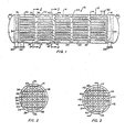
- FIG. 1 is a side elevation view of a heat exchanger employing a tube bundle constructed in accordance with the present invention with portions of the shell broken away to more clearly illustrate the internal construction thereof;
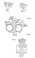
- FIG. 2 is a cross-sectional view taken along line 2-2 of FIG. 1;
- FIG. 3 is a cross-sectional view taken along line 3-3 of FIG. 1;
- FIG. 4 is an enlarged partial view of the tube bundle structure of FIG. 3 and illustrates the relative positions of the outer ring, baffle rods and tubes with the tubes loosely disposed between the rods;
- FIG. 5 is an enlarged partial view of the tube bundle structure, similar to FIG. 4, and illustrates the relative positions of the outer ring, baffle rods and tubes with the baffle rods moved to their second positions securely engaging the tubes, with the initial positions of the baffle rods and tubes indicated by dashed lines;
- FIG. 6 is a partial side elevation view of one form of baffle rod constructed in accordance with the present invention and having a substantially rectangular cross-section;
- FIG. 7 is a cross-sectional view taken along line 7-7 of FIG. 6..
- FIG. 8 is partial side elevation view of another form of baffle rod constructed in accordance with the present invention and having a substantially circular cross-section;
- FIG. 9 is a cross-sectional view taken along line 9-9 of FIG. 8;
- FIG. 10 is a partial side elevation view of another form of baffle rod constructed in accordance with the present invention and having a substantially circular cross-section;
- FIG. 11 is an enlarged cross-sectional detail view illustrating one form of securement between a baffle rod and an outer ring;
- FIG. 12 is an enlarged elevation detail view illustrating another form of securement between a baffle rod and an outer ring;
- FIG. 13 is an enlarged cross-sectional detail view illustrating a form of bolted securement between baffle rods and an outer ring; and
- FIG. 14 is an enlarged detail view taken along line 14-14 of FIG. 13.
- Referring now to the drawings, and to FIG. 1 in particular, a single pass shell and tube heat exchanger, generally designated by the
reference character 10, is illustrated therein. Theheat exchanger 10 comprises ashell 12 and atube bundle 14 positioned therein. - The
tube bundle 14 includes a pair oftube sheets 16 and 18 having apertures formed therein through which the opposite ends of a plurality oftubes 20 extend. The opposite ends of the tubes are secured to the respective tube sheets to provide support for the plurality of parallel alignedtubes 20. A pair ofbaffles 22 and a second pair ofbaffles 24 are positioned alternately along the longitudinal axes of theparallel tubes 20 in spaced relation and provide support for the tubes intermediate thetube sheets 16 and 18. While thebaffles tubes 20 of thetube bundle 14, it is possible to use baffles which are not in planes perpendicular or normal to the longitudinal axis of the tube bundle, however, baffles lying in perpendicular or normal planes as shown are more easily and economically constructed and are thus preferred. -
Nozzles heat exchanger 10 providing means for passing a first fluid through the tubes.Nozzles heat exchanger 10 and provide means for passing a second fluid over the outside surfaces of the tubes when preferably using countercurrent flow of the heat exchange fluids or mediums. - The
tubes 20 in theheat exchanger 10 are laid out in a square pitch, and generally a square pitch tube layout provides greater surface area for a given shell diameter for an apparatus constructed in accordance with the present invention. This layout of thetubes 20 is best illustrated in FIGS 2 and 3. It will be seen that thetubes 20 thus laid out form a plurality of vertically spaced horizontal tube rows and a plurality of horizontally spaced vertical tube rows. Thebaffles 22 illustrated in FIG. 2 comprise a baffle or supportingring 34 encircling thetubes 20. A plurality of horizontally extending baffle rods orbars 36 are fixedly secured at their opposite ends in the supportingring 34 and extend between alternate pairs of horizontal parallel tube rows. A plurality of vertically extending baffle rods orbars 38 are fixedly secured at their opposite ends in the supportingouter ring 34 and extend between alternate pairs of vertical parallel tube rows. The opposite ends of therods outer ring 34 by welding as shown in either FIG. 11 or FIG. 12, or may be belted thereto as illustrated in FIGS. 13 and 14. - The construction of the
baffle 24 is illustrated in FIG. 3. Thebaffle 24 comprises an outer supportingbaffle ring 40 which encircles thetubes 20 in a manner similar to that described for thering 34. A plurality of horizontally extending baffle rods orbars 42 are movably secured at their opposite ends in theouter ring 40 and extend between alternate pairs of horizontal parallel tube rows. It will be noted, however, that the tube rows between which therods 42 extend are not the tube rows between which therods 36 of thebaffle 22 extend. Therods 42 are positioned between horizontal tube rows which are open or unbaffled in thebaffle 22. Similarly, thebaffle 24 includes a plurality of vertically extending baffle rods orbars 44 movably secured at their opposite ends in the supportingouter ring 40 which rods extend between alternate pairs of vertical parallel tube rows. Therods 44 are not positioned between the same vertical tube rows ' through which the baffle rods 38 of thebaffle 22 extend, but rather extend between adjacent vertical tube rows which are open in thebaffle 22. - The
rods baffles 22 are of such thickness or diameter as to be closely received between the tubes of the adjacent horizontal and vertical tube rows, respectively. As best shown in FIGS. 4 and 5, the opposite ends of therods corresponding apertures outer ring 40. Each of therods first regions 50 of reduced thickness spaced along the length of the respective rod in correspondence to the center to center distance between thetubes 20 of adjacent tube rows. Theregions 50 of reduced thickness may be circular in cross-section as illustrated in FIGS. 4 and 5 and as further illustrated in FIG. 10, or otherwise shaped. Eachregion 50 of reduced thickness is preferably approximately 1/16-inch (1.5875 mm) less in thickness than the space between adjacent tubes in the tube row separated by the baffle rod. Thebaffle rods second regions 52 of increased thickness disposed adjacent thefirst regions 50 of reduced thickness. Theseregions 52 of increased thickness may be of either circular or rectangular cross-section. The thickness of thesecond regions 52 is preferably slightly greater than the nominal distance between adjacent tubes of the tube rows separated by the respective baffle rods. - FIG. 10 illustrates an enlarged portion of a baffle rod or bar 42 illustrating the
region 50 of reduced thickness and theregion 52 of increased thickness thereon. The rod illustrated in FIG. 10 is preferably circular in cross-section throughout its entire length. Thefirst region 50 of reduced thickness is arcuately shaped along the longitudinal axis of the rod, and conforms generally to the configuration of the outer surface of thetubes 20. It will be noted that the arcuate shape of theregion 50 of reduced thickness provides a thirdtransitional region 54 formed on the surface of the rod extending between the first andsecond regions - FIGS. 8 and 9 illustrate a slightly modified version of the rod or bar of FIG. 10 which will be designated by the reference character 42a. In the rod 42a, the
first regions 50 of reduced thickness and thesecond regions 52 of increased thickness are of circular cross-section as in therod 42. The third transitional region 54a interconnecting each of the first andsecond regions first region 50 to each correspondingsecond region 52. This configuration of the third transitional region 54a provides a more gradual transition between each region of reduced thickness and the corresponding region of increased thickness. - FIGS. 6 and 7 illustrate a third form of baffle rod or bar of substantially rectangular cross-section which is designated by the
reference character 42b. The first regions of reduced thickness of therod 42b are designated by thereference character 50b, and the second regions of increased thickness are designated by thereference character 52b. Eachregion 50b of reduced thickness is connected to acorresponding region 52b of increased thickness by a thirdtransitional region 54b formed on the surface of the rod of increasing rectangular cross-sectional area from the region of reduced thickness to the region of increased thickness. - FIGS. 13 and 14 illustrate the connections of the baffle rod or
bar 42b and a similarly constructed vertical baffle rod or bar 44b to a modified outer supporting ring designated by thereference character 40b. Theouter ring 40b comprises acentral ring member 56 and a pair ofexternal ring members 58 and 60 which cooperate with threadedbolts 62 to fixedly secure the outer ends of therods 42b and 44b to theouter ring 40b. - It should be noted at this point that the
rods regions 50 of reduced thickness between theregions 52 of increased thickness can be advantageously and economically formed by stamping whereby the regions of reduced thickness are substantially flat at their midpoints between adjacent regions of increased thickness. Such flat regions of reduced thickness are preferably oriented with the major axis thereof in alignment with the longitudinal axes of the tubes to thereby present a minimum cross-sectional area to the flow of fluid around the baffle rods and reduce the pressure drop of the flowing fluid across the rods. - To assemble the
heat exchanger 10, thetubes 20 are inserted through thebaffles rods baffles 24 are movably supported by the respective supporting rings 40 in the position illustrated in FIG. 4 thereby permitting the free passage of thetubes 20 through thebaffles tubes 20 are then received through the corresponding apertures 64 formed in thetube sheets 16 and 18. When suitably positioned, thetubes 20 are fixedly secured to thetube sheets 16 and 18 with the end of each tube forming a fluid tight seal with the corresponding aperture in the tube sheet. - The
rods baffles 24 are then driven or otherwise moved from their first positions as illustrated in FIG. 4 to their second positions as illustrated in FIG. 5, the dashed lines in FIG. 5 illustrating the previous positions for therods - When the
rods baffles 24 are positioned as illustrated in FIG. 5, the tubes of the adjacent tube rows are firmly engaged by thesecond regions 52 of increased thickness on therods outer ring 40 by suitable means such as by welding, as shown at 66 in FIG. 11, between therod 44 and the correspondingaperture 48 formed in thering 40 in which the rod is received. A similar weld connection is made between the end of eachrod 42 and the correspondingaperture 46 in thering 40. Eachaperture beveled portion 70 communicating with the outer periphery of the supportingring 40 in which aweld fillet 66 can be formed. The outer end of each rod is then cut off and contoured to conform to theouter periphery 72 of theouter ring 40 by suitable means such as grinding as shown at 74. - FIG. 12 illustrates a modified connection between a
baffle rod 44 and theouter ring 40 in which a transverse groove 76 is formed in theouter periphery 72 of thering 40 intersecting eachaperture rod 74 is again cut off and contoured to match theouter periphery 72 of theouter ring 40 by suitable means such as grinding. - In the event the alternate baffle structure illustrated in FIGS. 13 and 14 is employed, when the
rods 42b and 44t. are driven or otherwise moved to their second positions firmly engaging thetubes 20 with thesecond regions 52b of increased thickness thereof, the rods are then securely engaged to theouter ring 40b by tightening the threadedbolts 62 to secure.the rods between thering members outer periphery 72b of theouter ring 40b by suitable means such as grinding as described above. - Once the baffle rods of the
baffles 24 are fixedly secured in their second positions firmly engaging thetubes 20 with their outer ends contoured to conform to the outer periphery of the outer supporting rings, thetube bundle 14 thus assembled is inserted into the open end of theshell 12 and properly positioned therein at which time the open ends of theshell 12 are closed by suitable end caps 80 and 82. - It will be seen that the method and apparatus described above provides advantages in the construction of shell and tube heat exchangers, notably in the increased ease of assembly of this structure and in the reliable firm engagement of the tubes thereof intermediate their opposite ends. The transitional regions between the regions of reduced thickness and increased thickness facilitate the movement of the movable baffle rods from their first positions loosely engaging the tubes previously extended therepast to their second positions firmly engaging the tubes adjacent thereto.
- While four baffles, two having fixed baffle rods and two having movable baffle rods, have been described above, it will be readily apparent to those skilled in the art that various numbers of both fixed rod and movable rod baffles may be employed in the construction of a heat exchanger in accordance with the present invention depending upon various design constraints. Similarly, while a square pitch tube layout is described above, other tube layouts may be employed in a heat exchanger constructed in accordance with the present invention. It will be noted, however, that the square pitch tube layout disclosed herein when employed with the baffle structures also disclosed herein provides full radial support for the intermediate portions of the tubes of the heat exchanger. Further, while outer supporting rings of circular shape are herein disclosed, it will be understood that the present invention envisions annular baffle and tube supporting structures of other than circular shape depending on specific heat exchanger design considerations.
- Reasonable variations and modifications which will be apparent to those skilled in the art can be made in this invention without departing from the scope as defined in the claims.
Claims (14)
Applications Claiming Priority (2)
| Application Number | Priority Date | Filing Date | Title |
|---|---|---|---|
| US86412277A | 1977-12-23 | 1977-12-23 | |
| US864122 | 1977-12-23 |
Publications (2)
| Publication Number | Publication Date |
|---|---|
| EP0002823A1 EP0002823A1 (en) | 1979-07-11 |
| EP0002823B1 true EP0002823B1 (en) | 1981-07-08 |
Family
ID=25342580
Family Applications (1)
| Application Number | Title | Priority Date | Filing Date |
|---|---|---|---|
| EP78101829A Expired EP0002823B1 (en) | 1977-12-23 | 1978-12-22 | Tube bundle assembly and process for its construction |
Country Status (11)
| Country | Link |
|---|---|
| EP (1) | EP0002823B1 (en) |
| JP (1) | JPS5489360A (en) |
| AU (1) | AU509892B2 (en) |
| CA (1) | CA1103658A (en) |
| DD (1) | DD141196A5 (en) |
| DE (1) | DE2860833D1 (en) |
| DK (1) | DK545678A (en) |
| ES (1) | ES476084A1 (en) |
| NO (1) | NO147125B (en) |
| YU (1) | YU289778A (en) |
| ZA (1) | ZA786655B (en) |
Families Citing this family (11)
| Publication number | Priority date | Publication date | Assignee | Title |
|---|---|---|---|---|
| US4286366A (en) * | 1977-12-23 | 1981-09-01 | Phillips Petroleum Company | Method for the construction of a baffled heat exchanger |
| US4398595A (en) * | 1979-11-29 | 1983-08-16 | Phillips Petroleum Company | Vortex generators |
| US4413394A (en) * | 1979-11-29 | 1983-11-08 | Phillips Petroleum Company | Method of constructing a tube bundle |
| US4311187A (en) * | 1979-11-29 | 1982-01-19 | Phillips Petroleum Company | Vortex generators |
| US4299276A (en) * | 1980-04-21 | 1981-11-10 | Phillips Petroleum Company | Heat exchanger having radial support |
| US4640342A (en) * | 1984-01-26 | 1987-02-03 | Westinghouse Electric Corp. | Expandable antivibration bar for heat transfer tubes of a pressurized water reactor steam generator |
| US4653576A (en) * | 1985-05-01 | 1987-03-31 | Westinghouse Electric Corp. | Expandable antivibration bar for a steam generator |
| US5005637A (en) * | 1986-11-05 | 1991-04-09 | Phillips Petroleum Company | Heat exchanger U-bend tube support |
| US5388638A (en) * | 1993-12-28 | 1995-02-14 | Phillips Petroleum Company | Rod baffle heat exchanger |
| FR2787875B1 (en) * | 1998-12-29 | 2001-06-08 | Valeo Thermique Moteur Sa | FLEXIBLE TUBE HEAT EXCHANGER, PARTICULARLY FOR A COOLING SYSTEM OF A MOTOR VEHICLE ENGINE |
| US11047266B2 (en) | 2019-10-30 | 2021-06-29 | General Electric Company | Heat exchanger with heat exchange tubes moveable between aligned and non-aligned positions |
Family Cites Families (8)
| Publication number | Priority date | Publication date | Assignee | Title |
|---|---|---|---|---|
| CH491313A (en) * | 1968-01-23 | 1970-05-31 | Sulzer Ag | Heat exchanger |
| DE2204280A1 (en) * | 1972-01-29 | 1973-08-30 | Babcock & Wilcox Ag | HEAT EXCHANGER WITH PIPES LONG IN RELATION TO THE PIPE DIAMETER |
| GB1404643A (en) * | 1972-09-23 | 1975-09-03 | Clarke Chapman Ltd | Heat exchanger |
| NO132704C (en) * | 1973-04-10 | 1975-12-17 | Norsk Hydro As | |
| JPS51111949A (en) * | 1975-03-04 | 1976-10-02 | Westinghouse Electric Corp | Device for locking finned zigzag tube |
| DE7537348U (en) * | 1975-10-23 | 1976-04-01 | Tubor S.A., Tenero (Schweiz) | Spacer for tall tubular radiators |
| CA1067483A (en) * | 1976-04-29 | 1979-12-04 | Phillips Petroleum Company | Baffle |
| DE7802361U1 (en) * | 1978-01-27 | 1978-07-06 | Ceagfilter Und Entstaubungstechnik Gmbh, 4600 Dortmund | AIR PREHEATER |
-
1978
- 1978-11-27 ZA ZA00786655A patent/ZA786655B/en unknown
- 1978-11-29 AU AU42042/78A patent/AU509892B2/en not_active Expired
- 1978-11-30 DK DK545678A patent/DK545678A/en unknown
- 1978-12-11 YU YU02897/78A patent/YU289778A/en unknown
- 1978-12-13 CA CA317,840A patent/CA1103658A/en not_active Expired
- 1978-12-18 ES ES476084A patent/ES476084A1/en not_active Expired
- 1978-12-18 JP JP15622678A patent/JPS5489360A/en active Pending
- 1978-12-22 DD DD78210119A patent/DD141196A5/en unknown
- 1978-12-22 EP EP78101829A patent/EP0002823B1/en not_active Expired
- 1978-12-22 NO NO784373A patent/NO147125B/en unknown
- 1978-12-22 DE DE7878101829T patent/DE2860833D1/en not_active Expired
Also Published As
| Publication number | Publication date |
|---|---|
| ZA786655B (en) | 1979-10-31 |
| ES476084A1 (en) | 1979-11-16 |
| EP0002823A1 (en) | 1979-07-11 |
| AU4204278A (en) | 1979-07-05 |
| AU509892B2 (en) | 1980-05-29 |
| YU289778A (en) | 1983-01-21 |
| JPS5489360A (en) | 1979-07-16 |
| DD141196A5 (en) | 1980-04-16 |
| CA1103658A (en) | 1981-06-23 |
| DK545678A (en) | 1979-06-24 |
| DE2860833D1 (en) | 1981-10-15 |
| NO784373L (en) | 1979-06-26 |
| NO147125B (en) | 1982-10-25 |
Similar Documents
| Publication | Publication Date | Title |
|---|---|---|
| US4286366A (en) | Method for the construction of a baffled heat exchanger | |
| US4450904A (en) | Heat exchanger having means for supporting the tubes in spaced mutually parallel relation and suppressing vibration | |
| US4871014A (en) | Shell and tube heat exchanger | |
| EP0002823B1 (en) | Tube bundle assembly and process for its construction | |
| US7219718B2 (en) | Reduced vibration tube bundle device | |
| US4398595A (en) | Vortex generators | |
| JP3634477B2 (en) | Heat exchanger | |
| US5642778A (en) | Rod baffle heat exchangers | |
| US5005637A (en) | Heat exchanger U-bend tube support | |
| US4386456A (en) | Method of assembling a unitary heat exchanger tube bundle assembly | |
| EP0030012B1 (en) | Process for improving heat transfer coefficient, method of constructing a tube bundle and apparatus having a plurality of parallel tubes | |
| US4142580A (en) | Bayonet heat exchanger having means for positioning bayonet tube in sheath tube | |
| US4325171A (en) | Means and method for sealing heat exchanger walls | |
| EP0661509B1 (en) | Improved rod baffle heat exchanger | |
| US4697637A (en) | Tube support and flow director | |
| US2607567A (en) | Heat exchanger | |
| US4154295A (en) | Heat exchanger tube support assembly | |
| US3324942A (en) | Heat exchanger bundle | |
| US5411080A (en) | Baffle rings for retrofit of existing shell-and-tube heat exchangers | |
| JPH06185891A (en) | Rod baffle of tubular type heat exchanger | |
| JPH06180190A (en) | Cylindrical shell and tube heat exchanger | |
| CA1109058A (en) | Helical spacer for heat exchanger tube bundle | |
| GB2142716A (en) | Shell- and tube-type heat exchangers | |
| JPH01296092A (en) | Parallel flow multi-tube type heat exchanger and manufacture thereof | |
| JPS62129696A (en) | Supporting structure for heat transfer pipes with fins |
Legal Events
| Date | Code | Title | Description |
|---|---|---|---|
| PUAI | Public reference made under article 153(3) epc to a published international application that has entered the european phase |
Free format text: ORIGINAL CODE: 0009012 |
|
| AK | Designated contracting states |
Designated state(s): BE DE FR GB IT NL SE |
|
| 17P | Request for examination filed | ||
| ITF | It: translation for a ep patent filed |
Owner name: ING. C. GREGORJ S.P.A. |
|
| GRAA | (expected) grant |
Free format text: ORIGINAL CODE: 0009210 |
|
| AK | Designated contracting states |
Designated state(s): BE DE FR GB IT NL SE |
|
| REF | Corresponds to: |
Ref document number: 2860833 Country of ref document: DE Date of ref document: 19811015 |
|
| PGFP | Annual fee paid to national office [announced via postgrant information from national office to epo] |
Ref country code: NL Payment date: 19811231 Year of fee payment: 4 |
|
| PGFP | Annual fee paid to national office [announced via postgrant information from national office to epo] |
Ref country code: DE Payment date: 19820802 Year of fee payment: 5 |
|
| PGFP | Annual fee paid to national office [announced via postgrant information from national office to epo] |
Ref country code: FR Payment date: 19820803 Year of fee payment: 5 |
|
| PGFP | Annual fee paid to national office [announced via postgrant information from national office to epo] |
Ref country code: SE Payment date: 19820930 Year of fee payment: 5 Ref country code: BE Payment date: 19820930 Year of fee payment: 5 |
|
| PG25 | Lapsed in a contracting state [announced via postgrant information from national office to epo] |
Ref country code: NL Effective date: 19830701 |
|
| NLV4 | Nl: lapsed or anulled due to non-payment of the annual fee | ||
| PG25 | Lapsed in a contracting state [announced via postgrant information from national office to epo] |
Ref country code: SE Effective date: 19831223 |
|
| BERE | Be: lapsed |
Owner name: PHILLIPS PETROLEUM CY Effective date: 19840601 |
|
| PG25 | Lapsed in a contracting state [announced via postgrant information from national office to epo] |
Ref country code: BE Effective date: 19840630 |
|
| GBPC | Gb: european patent ceased through non-payment of renewal fee | ||
| PG25 | Lapsed in a contracting state [announced via postgrant information from national office to epo] |
Ref country code: FR Free format text: LAPSE BECAUSE OF NON-PAYMENT OF DUE FEES Effective date: 19840831 |
|
| PG25 | Lapsed in a contracting state [announced via postgrant information from national office to epo] |
Ref country code: DE Effective date: 19840901 |
|
| REG | Reference to a national code |
Ref country code: FR Ref legal event code: ST |
|
| PG25 | Lapsed in a contracting state [announced via postgrant information from national office to epo] |
Ref country code: GB Effective date: 19881117 |
|
| EUG | Se: european patent has lapsed |
Ref document number: 78101829.6 Effective date: 19850605 |
|
| PLBE | No opposition filed within time limit |
Free format text: ORIGINAL CODE: 0009261 |
|
| STAA | Information on the status of an ep patent application or granted ep patent |
Free format text: STATUS: NO OPPOSITION FILED WITHIN TIME LIMIT |