EP0002190B1 - Vorrichtung zur Darstellung eines Bildes vor einem optisch kontrastierenden Hintergrund - Google Patents
Vorrichtung zur Darstellung eines Bildes vor einem optisch kontrastierenden Hintergrund Download PDFInfo
- Publication number
- EP0002190B1 EP0002190B1 EP78101262A EP78101262A EP0002190B1 EP 0002190 B1 EP0002190 B1 EP 0002190B1 EP 78101262 A EP78101262 A EP 78101262A EP 78101262 A EP78101262 A EP 78101262A EP 0002190 B1 EP0002190 B1 EP 0002190B1
- Authority
- EP
- European Patent Office
- Prior art keywords
- display elements
- display
- switched
- image
- fluorescent particles
- Prior art date
- Legal status (The legal status is an assumption and is not a legal conclusion. Google has not performed a legal analysis and makes no representation as to the accuracy of the status listed.)
- Expired
Links
- 238000010521 absorption reaction Methods 0.000 claims description 12
- 239000002245 particle Substances 0.000 claims description 6
- 230000000694 effects Effects 0.000 claims description 5
- 230000005699 Stark effect Effects 0.000 claims description 3
- 238000004519 manufacturing process Methods 0.000 claims description 3
- 239000000463 material Substances 0.000 claims description 3
- 230000005855 radiation Effects 0.000 claims description 3
- 230000005684 electric field Effects 0.000 claims 1
- 239000004973 liquid crystal related substance Substances 0.000 description 2
- 239000000126 substance Substances 0.000 description 2
- 238000011161 development Methods 0.000 description 1
- 230000018109 developmental process Effects 0.000 description 1
- 238000000295 emission spectrum Methods 0.000 description 1
- 230000002349 favourable effect Effects 0.000 description 1
- 230000005669 field effect Effects 0.000 description 1
- 238000001914 filtration Methods 0.000 description 1
- 239000012212 insulator Substances 0.000 description 1
- 239000007788 liquid Substances 0.000 description 1
- 239000004065 semiconductor Substances 0.000 description 1
- 239000007787 solid Substances 0.000 description 1
- 230000007704 transition Effects 0.000 description 1
Images
Classifications
-
- G—PHYSICS
- G02—OPTICS
- G02F—OPTICAL DEVICES OR ARRANGEMENTS FOR THE CONTROL OF LIGHT BY MODIFICATION OF THE OPTICAL PROPERTIES OF THE MEDIA OF THE ELEMENTS INVOLVED THEREIN; NON-LINEAR OPTICS; FREQUENCY-CHANGING OF LIGHT; OPTICAL LOGIC ELEMENTS; OPTICAL ANALOGUE/DIGITAL CONVERTERS
- G02F1/00—Devices or arrangements for the control of the intensity, colour, phase, polarisation or direction of light arriving from an independent light source, e.g. switching, gating or modulating; Non-linear optics
- G02F1/01—Devices or arrangements for the control of the intensity, colour, phase, polarisation or direction of light arriving from an independent light source, e.g. switching, gating or modulating; Non-linear optics for the control of the intensity, phase, polarisation or colour
- G02F1/13—Devices or arrangements for the control of the intensity, colour, phase, polarisation or direction of light arriving from an independent light source, e.g. switching, gating or modulating; Non-linear optics for the control of the intensity, phase, polarisation or colour based on liquid crystals, e.g. single liquid crystal display cells
- G02F1/133—Constructional arrangements; Operation of liquid crystal cells; Circuit arrangements
- G02F1/1333—Constructional arrangements; Manufacturing methods
- G02F1/1335—Structural association of cells with optical devices, e.g. polarisers or reflectors
- G02F1/1336—Illuminating devices
- G02F1/133617—Illumination with ultraviolet light; Luminescent elements or materials associated to the cell
-
- F—MECHANICAL ENGINEERING; LIGHTING; HEATING; WEAPONS; BLASTING
- F21—LIGHTING
- F21K—NON-ELECTRIC LIGHT SOURCES USING LUMINESCENCE; LIGHT SOURCES USING ELECTROCHEMILUMINESCENCE; LIGHT SOURCES USING CHARGES OF COMBUSTIBLE MATERIAL; LIGHT SOURCES USING SEMICONDUCTOR DEVICES AS LIGHT-GENERATING ELEMENTS; LIGHT SOURCES NOT OTHERWISE PROVIDED FOR
- F21K2/00—Non-electric light sources using luminescence; Light sources using electrochemiluminescence
-
- G—PHYSICS
- G09—EDUCATION; CRYPTOGRAPHY; DISPLAY; ADVERTISING; SEALS
- G09F—DISPLAYING; ADVERTISING; SIGNS; LABELS OR NAME-PLATES; SEALS
- G09F13/00—Illuminated signs; Luminous advertising
- G09F13/20—Illuminated signs; Luminous advertising with luminescent surfaces or parts
Definitions
- the invention relates to a device according to the preamble of claim 1.
- a display is known from "Electronics” 6 (1977) 55, where the principle of a “fluorescence-activated display (FLAD)" is generally shown.
- a FLAD with a so-called rotary cell had always been used as a light valve.
- Such a liquid crystal display is known to provide a high display contrast with low power losses and low switching voltages.
- a rotary cell switches relatively slowly, has only a limited viewing angle range, does not allow contrast gradations without further ado and, moreover, should be controlled with a pure AC voltage, a requirement which is difficult to meet, particularly in the multiplex mode which is increasingly coming to the fore .
- the production of a rotary cell still requires special care and therefore the transition to series production has often not yet been successful. This situation, which is not yet quite satisfactory, will - according to the expectation expressed in the cited literature reference - only significantly improve if the rotary cell is replaced by a liquid crystal display with dye addition and a “phase change” effect or by an electrochromic display.
- the object of the present invention is to design a FLAD of the type mentioned at the outset in such a way that it works practically without loss, can be switched without particularly high voltages and can also be read from oblique directions, has an easily controllable image contrast and also operates with Tolerates DC components.
- This object is achieved according to the invention by the device characterized in claim 1.
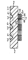
- the figure shows a diagrammatic side section of a display device, the display of which is a single-digit display.
- the display device contains a fluorescence plate 1, the side surfaces of which carry a reflection layer 2 and on the back of which are made in the form of an “8” notches 3.
- these notches are each additionally provided with a mirror layer (“dielectric mirror” 4).
- display elements 5 are placed on the front of the plate.
- Each display element consists in detail of a diffuser 6, a front electrically conductive layer (front electrode 7), an electrochromic layer 8, a rear electrically conductive layer (back electrode 9) and a cover layer 11 adjacent to the fluorescent plate.
- the layers 11 and 6 could also be omitted .
- the fluorescent particles are selected so that they have a narrow-band emission spectrum of a few 10 nm. Examples of such fluorescent substances - dissolved in a liquid - are mentioned in DE-OS 27 42 899.
- the dielectric mirrors 4 are designed in such a way that they only reflect about a 10 nm wide frequency section forward from the fluorescence radiation and allow the other frequencies to pass.
- the electrochromic layer 8 consists of a material which shows a pronounced Franz-Keldysch effect and has an absorption band, the displaceable edge of which lies approximately at the upper limit frequency of the light coupled out from the light exit windows. With these band positions, each display element lights up in a certain color when it is idle.
- the display device is to be addressed “complementarily” or “inversely” in accordance with the light-off state and the dark on-state.
Landscapes
- Physics & Mathematics (AREA)
- Nonlinear Science (AREA)
- Engineering & Computer Science (AREA)
- General Physics & Mathematics (AREA)
- Optics & Photonics (AREA)
- Crystallography & Structural Chemistry (AREA)
- Chemical & Material Sciences (AREA)
- Electromagnetism (AREA)
- Mathematical Physics (AREA)
- General Engineering & Computer Science (AREA)
- Theoretical Computer Science (AREA)
- Devices For Indicating Variable Information By Combining Individual Elements (AREA)
- Electrochromic Elements, Electrophoresis, Or Variable Reflection Or Absorption Elements (AREA)
Description
- Die Erfindung betrifft eine Vorrichtung gemäß dem Oberbegriff des Anspruchs 1. Ein solches Display ist aus »Elektronik« 6 (1977) 55 bekannt, wo allgemein das Prinzip eines »fluoreszenzaktivierten Displays (FLAD)« dargestellt wird.
- Bisher hatte man ein FLAD stets mit einer sogenannten Drehzelle (DE-AS 21 58 563) als Lichtventil verwendet. Ein derartiges Flüssigkristalldisplay liefert bekanntlich bei geringen Verlustleistungen und niedrigen Schaltspannungen einen hohen Darstellungskontrast. Nachteilig ist allerdings, daß eine Drehzelle relativ langsam schaltet, einen nur begrenzten Betrachtungswinkelbereich hat, nicht ohne weiteres Kontrastabstufungen zuläßt und überdies mit einer reinen Wechselspannung angesteuert werden sollte, eine Forderung, die gerade bei den zunehmend in den Vordergrund tretenden Multiplexbetrieb nur schwer zu erfüllen ist. Hinzu kommt, daß die Herstellung einer Drehzelle nach wie vor eine besondere Sorgfalt erfordert und daher der Übergang zur Serienfertigung häufig noch nicht gelungen ist. Diese noch nicht recht befriedigende Situation wird sich - so die in der zitierten Literaturstelle ausgesprochene Erwartung - erst dann wesentlich verbessern, wenn die Drehzelle durch ein Flüssigkristalldisplay mit Farbstoffzusatz und »Phase-change«-Effekt oder durch ein elektrochromes Display ersetzt wird.
- Aufgabe der vorliegenden Erfindung ist es, ein FLAD der eingangs genannten Art so auszubilden, daß es praktisch verlustfrei arbeitet, ohne sonderlich hohe Spannungen geschaltet werden kann und zudem auch aus schrägen Richtungen abgelesen werden kann, über einen leicht steuerbaren Bildkontrast verfügt und auch einen Betrieb mit Gleichspannungskomponenten verträgt. Diese Aufgabe wird erfindungsgemäß durch die im Anspruch 1 gekennzeichnete Vorrichtung gelöst.
- Der von Franz und Keldysch als Tunneleffekt gedeutete und nach den beiden Wissenschaftlern benannte Feldeffekt besteht darin, daß in Isolatoren oder Halbleitern unter dem Einfluß hoher E-Felder die untere Bandkante des Absorptionsbandes nach längeren Wellenlängen hin verschoben wird (Z. Naturforsch. 13a (1958) 484). Der (lineare und quadratische) Stark-Effekt zeigt sich in einer Erhöhung und Verschiebung des Absorptionsmaximus (US-PS 33 17 266). Beide Phänomene werden in der Monographie von I. F. Chang »Electrochromic and Electrochemichromic Materials and Phenomena« IBM Research, R C 5663 v. 26. 9. 75, insb. Abschnitte III.C und III.D im einzelnen beschrieben.
- Da beim Franz-Keldysch-Effekt wie auch beim Stark-Effekt die bisher beobachteten Frequenzverschiebungen vergleichsweise gering sind, werden nur Fluoreszenzstoffe verwendet, die schmalbandig emittieren. Dabei ließe sich der Kontrast noch dadurch erhöhen, daß man das Emissionsband durch zusätzliche Maßnahmen wie Ausfilterungen weiter einengt. Im Normalfall wird das Absorptionsband im ausgeschalteten Zustand das Emissionsband abdecken und im eingeschalteten Zustand, also unter Einfluß eines hinreichend großen E-Feldes, das Fluoreszenzlicht freigeben. Es ist aber auch denkbar und in vielen Fällen, wie statistische Betrachtungen zeigen, vom Leistungsverbrauch her gesehen sogar günstiger, einen Aus-Zustand zu wählen, bei dem das Emissionsband außerhalb des Absorptionsbandes der Anzeigeelemente liegt und im Ein-Zustand vom Absorptionsband überdeckt wird. In diesem Fall wären bei der hier vorgeschlagenen Vorrichtung jeweils gerade diejenigen Anzeigeelemente einzuschalten, die nicht zum Bild, sondern zum Bildhintergrund gehören.
- Weiter vorteilhafte Ausgestaltungen und Weiterbildungen der Erfindung sind Gegenstand zusätzlicher Ansprüche.
- Die Erfindung soll nun anhand eines bevorzugten Ausführungsbeispiels in Verbindung mit der beigefügten Figur näher erläutert werden.
- Die Figur zeigt in einem schematisch gehaltenen Seitenschnitt eine Darstellungsvorrichtung, deren Display eine einstellige Ziffernanzeige ist. Die Anzeigevorrichtung enthält eine Fluoreszenzplatte 1, deren Seitenflächen eine Reflexionsschicht 2 tragen und auf deren Rückseite in Form einer »8« Kerben 3 eingebracht sind. Diese Kerben sind im vorliegenden Fall noch zusätzlich jeweils mit einer Spiegelschicht (»dielektrischer Spiegel« 4) versehen. In Blickrichtung vor den Kerben sind jeweils Anzeigeelemente 5 auf die Vorderseite der Platte gesetzt. Jedes Anzeigeelement besteht im einzelnen aus einem Diffusor 6, einer vorderen elektrisch leitenden Schicht (Vorderelektrode 7), einer elektrochromen Schicht 8, einer hinteren elektrisch leitenden Schicht (Rückelektrode 9) und einer der Fluoreszenzplatte anliegenden Abdeckschicht 11. Die Schichten 11 und 6 könnten auch entfallen.
- Die fluoreszierenden Partikel sind so gewählt, daß sie ein schmalbandiges Emissionsspektrum von einigen 10 nm haben. Beispiele derartiger Fluoreszenzstoffe - gelöst in einer Flüssigkeit - sind in der DE-OS 27 42 899 genannt. Um das Fluoreszenzband noch weiter einzuengen, sind die dielektrischen Spiegel 4 so ausgelegt, daß sie von der Fluoreszenzstrahlung nur etwa einen 10 nm breiten Frequenzausschnitt nach vorn reflektieren und die übrigen Frequenzen passieren lassen. Die elektrochrome Schicht 8 besteht aus einem Material, das einen ausgeprägten Franz-Keldysch-Effekt zeigt, und hat ein Absorptionsband, dessen verschiebbare Kante etwa an der oberen Grenzfrequenz des von den Lichtaustrittsfenstern ausgekoppelten Lichts liegt. Bei diesen Bandpositionen leuchtet jedes Anzeigeelement im Ruhezustand in einem bestimmten Farbton. Legt man eine elektrische Spannung an das Anzeigeelement, so bewegt sich die Absorptionskante der elektrochromen Schicht in das Durchlaßband der dielektrischen Spiegel hinein, bis es bei einem hinreichend starken E-Feld das gesamte Licht der Lichtaustrittsfenster sperrt. In diesem Zustand erscheint das Anzeigeelement dunkel. Entsprechend dem hellen Aus-Zustand und dem dunklen Ein-Zustand ist die Anzeigevorrichtung »komplementär« bzw. »invers« zu adressieren.
- Da sich nur vor den Lichtaustrittsfenstern kleinflächige Anzeigeelemente befinden, kann Umgebungslicht auch von vorn in die Fluoreszenzplatte eintreten; dadurch nimmt der Helligkeitsverstärkungsfaktor der Platte einen sehr hohen Wert an. Auch der Raumwinkelbereich, aus dem die dargestellte Information noch erkannt werden kann, ist sehr hoch, weil die einzelnen Lichtventile flach sind.
Claims (6)
Applications Claiming Priority (2)
| Application Number | Priority Date | Filing Date | Title |
|---|---|---|---|
| DE19772753203 DE2753203A1 (de) | 1977-11-29 | 1977-11-29 | Verfahren zur darstellung eines bildes vor einem optisch kontrastierenden hintergrund |
| DE2753203 | 1977-11-29 |
Related Child Applications (1)
| Application Number | Title | Priority Date | Filing Date |
|---|---|---|---|
| EP80102542.0 Division-Into | 1978-10-30 |
Publications (2)
| Publication Number | Publication Date |
|---|---|
| EP0002190A1 EP0002190A1 (de) | 1979-06-13 |
| EP0002190B1 true EP0002190B1 (de) | 1981-08-12 |
Family
ID=6024887
Family Applications (2)
| Application Number | Title | Priority Date | Filing Date |
|---|---|---|---|
| EP80102542A Withdrawn EP0019229A1 (de) | 1977-11-29 | 1978-10-30 | Vorrichtung zur Darstellung eines Bildes vor einem optisch kontrastierenden Hintergrund |
| EP78101262A Expired EP0002190B1 (de) | 1977-11-29 | 1978-10-30 | Vorrichtung zur Darstellung eines Bildes vor einem optisch kontrastierenden Hintergrund |
Family Applications Before (1)
| Application Number | Title | Priority Date | Filing Date |
|---|---|---|---|
| EP80102542A Withdrawn EP0019229A1 (de) | 1977-11-29 | 1978-10-30 | Vorrichtung zur Darstellung eines Bildes vor einem optisch kontrastierenden Hintergrund |
Country Status (5)
| Country | Link |
|---|---|
| US (1) | US4269480A (de) |
| EP (2) | EP0019229A1 (de) |
| JP (1) | JPS54100295A (de) |
| DE (1) | DE2753203A1 (de) |
| IT (1) | IT1100178B (de) |
Families Citing this family (2)
| Publication number | Priority date | Publication date | Assignee | Title |
|---|---|---|---|---|
| US4419663A (en) * | 1979-03-14 | 1983-12-06 | Matsushita Electric Industrial Co., Ltd. | Display device |
| US4678285A (en) * | 1984-01-13 | 1987-07-07 | Ricoh Company, Ltd. | Liquid crystal color display device |
Family Cites Families (5)
| Publication number | Priority date | Publication date | Assignee | Title |
|---|---|---|---|---|
| US3317266A (en) * | 1963-05-16 | 1967-05-02 | Ibm | Electrochromic light valve |
| US3496410A (en) * | 1967-11-13 | 1970-02-17 | Sanders Associates Inc | Electroluminescent display device producing a graphical display in a selected color |
| US3656835A (en) * | 1969-08-26 | 1972-04-18 | Du Pont | Modulation by a magnetic field of electromagnetic radiation produced by the decay of triplet states |
| DE2616669C2 (de) * | 1976-04-15 | 1986-10-09 | Licentia Patent-Verwaltungs-Gmbh, 6000 Frankfurt | Strahlungskollektor und -verdichter in Form einer fluoreszierenden Kunststoffplatte und Anzeigevorrichtung hiermit |
| DE2619367A1 (de) * | 1976-04-30 | 1977-11-17 | Siemens Ag | Fluessigkristallanzeige mit zusatzbeleuchtung |
-
1977
- 1977-11-29 DE DE19772753203 patent/DE2753203A1/de not_active Ceased
-
1978
- 1978-10-30 EP EP80102542A patent/EP0019229A1/de not_active Withdrawn
- 1978-10-30 EP EP78101262A patent/EP0002190B1/de not_active Expired
- 1978-11-17 US US05/961,730 patent/US4269480A/en not_active Expired - Lifetime
- 1978-11-22 IT IT30046/78A patent/IT1100178B/it active
- 1978-11-28 JP JP14706978A patent/JPS54100295A/ja active Pending
Also Published As
| Publication number | Publication date |
|---|---|
| IT1100178B (it) | 1985-09-28 |
| US4269480A (en) | 1981-05-26 |
| EP0019229A1 (de) | 1980-11-26 |
| EP0002190A1 (de) | 1979-06-13 |
| IT7830046A0 (it) | 1978-11-22 |
| DE2753203A1 (de) | 1979-05-31 |
| JPS54100295A (en) | 1979-08-07 |
Similar Documents
| Publication | Publication Date | Title |
|---|---|---|
| DE2419170C3 (de) | Flüssigkristall-Bildschirm mit Matrixansteuerung | |
| DE69212591T2 (de) | Projektionsschirm fuer bilder | |
| DE2246250C2 (de) | Elektro-optische Vorrichtung | |
| DE69831495T2 (de) | Intelligente elektrophotochrome fenster | |
| DE2739613C2 (de) | Elektrochromatische Anzeigevorrichtung | |
| EP0008400A1 (de) | Anzeigevorrichtung mit einer Flüssigkristallzelle und Verfahren zum Betrieb einer solchen Anzeigevorrichtung | |
| EP0470597A2 (de) | Elektrochrome Vorrichtung | |
| DE3736075A1 (de) | Elektrochromes schichtenpaket | |
| DE3308438A1 (de) | Elektroskopische sichtgeraete | |
| DE2459488A1 (de) | Fluessigkristall-verbundanzeigeschirm (-zelle) | |
| DE3513988A1 (de) | Anwendung des elektrolyseverfahrens zum veraendern des reflexionsgrades von spiegeln | |
| EP0811871A2 (de) | Elektrochrome Einheit | |
| EP0412408B1 (de) | Elektrisch leitfähige Polymere und ihre Verwendung als Orientierungsschicht in Flüssigkristall-Schalt- und Anzeigeelementen | |
| DE2355134C2 (de) | Anzeigevorrichtung | |
| DE2434889A1 (de) | Fluessigkristall-anzeigeelement | |
| DE2125337C3 (de) | Anordnung mit veränderlicher Lichtdurchlässigkeit | |
| DE69118377T2 (de) | Varistorgesteuerte flüssigkristallanzeigevorrichtung | |
| DE2910952A1 (de) | Vorrichtung zur verbesserung der erkennbarkeit von passiven displays | |
| DE2858076C2 (de) | Verfahren zur Ansteuerung einer elektrochromen Anzeigevorrichtung | |
| DE2542189A1 (de) | Fluessigkristall-anzeige mit bistabiler cholesterinischer fluessigkristall- schicht | |
| DE2616669C2 (de) | Strahlungskollektor und -verdichter in Form einer fluoreszierenden Kunststoffplatte und Anzeigevorrichtung hiermit | |
| CH622637A5 (en) | Display device for presenting characters | |
| EP1076841B1 (de) | Photoelektrochromes Bauelement | |
| DE2808440B2 (de) | ||
| DE2542235C3 (de) | Flüssigkristall-Anzeige mit bistabiler cholesterinischer Flüssigkristall-Schicht |
Legal Events
| Date | Code | Title | Description |
|---|---|---|---|
| PUAI | Public reference made under article 153(3) epc to a published international application that has entered the european phase |
Free format text: ORIGINAL CODE: 0009012 |
|
| AK | Designated contracting states |
Designated state(s): CH FR GB NL SE |
|
| 17P | Request for examination filed | ||
| GRAA | (expected) grant |
Free format text: ORIGINAL CODE: 0009210 |
|
| AK | Designated contracting states |
Designated state(s): CH FR GB NL SE |
|
| PG25 | Lapsed in a contracting state [announced via postgrant information from national office to epo] |
Ref country code: CH Effective date: 19810812 |
|
| PG25 | Lapsed in a contracting state [announced via postgrant information from national office to epo] |
Ref country code: SE Effective date: 19811031 |
|
| PG25 | Lapsed in a contracting state [announced via postgrant information from national office to epo] |
Ref country code: NL Effective date: 19820501 |
|
| NLV4 | Nl: lapsed or anulled due to non-payment of the annual fee |
Effective date: 19820501 |
|
| PG25 | Lapsed in a contracting state [announced via postgrant information from national office to epo] |
Ref country code: FR Free format text: LAPSE BECAUSE OF NON-PAYMENT OF DUE FEES Effective date: 19820630 |
|
| REG | Reference to a national code |
Ref country code: CH Ref legal event code: PL |
|
| GBPC | Gb: european patent ceased through non-payment of renewal fee | ||
| PG25 | Lapsed in a contracting state [announced via postgrant information from national office to epo] |
Ref country code: GB Effective date: 19881117 |
|
| EUG | Se: european patent has lapsed |
Ref document number: 78101262.0 Effective date: 19820505 |
|
| PLBE | No opposition filed within time limit |
Free format text: ORIGINAL CODE: 0009261 |
|
| STAA | Information on the status of an ep patent application or granted ep patent |
Free format text: STATUS: NO OPPOSITION FILED WITHIN TIME LIMIT |