EP0001718B1 - Apparatus and method for use in the removal of material from body cavities by suction - Google Patents
Apparatus and method for use in the removal of material from body cavities by suction Download PDFInfo
- Publication number
- EP0001718B1 EP0001718B1 EP78300537A EP78300537A EP0001718B1 EP 0001718 B1 EP0001718 B1 EP 0001718B1 EP 78300537 A EP78300537 A EP 78300537A EP 78300537 A EP78300537 A EP 78300537A EP 0001718 B1 EP0001718 B1 EP 0001718B1
- Authority
- EP
- European Patent Office
- Prior art keywords
- catheter
- suction
- container
- collection container
- liquid
- Prior art date
- Legal status (The legal status is an assumption and is not a legal conclusion. Google has not performed a legal analysis and makes no representation as to the accuracy of the status listed.)
- Expired
Links
- 239000000463 material Substances 0.000 title claims description 52
- 238000000034 method Methods 0.000 title claims description 7
- 239000007788 liquid Substances 0.000 claims description 29
- 238000005406 washing Methods 0.000 claims description 20
- 230000008878 coupling Effects 0.000 claims description 3
- 238000010168 coupling process Methods 0.000 claims description 3
- 238000005859 coupling reaction Methods 0.000 claims description 3
- 230000035515 penetration Effects 0.000 claims description 2
- 210000004291 uterus Anatomy 0.000 description 13
- 208000027418 Wounds and injury Diseases 0.000 description 10
- 210000003679 cervix uteri Anatomy 0.000 description 10
- 230000006378 damage Effects 0.000 description 10
- 208000014674 injury Diseases 0.000 description 10
- 239000002184 metal Substances 0.000 description 10
- 239000008280 blood Substances 0.000 description 6
- 210000004369 blood Anatomy 0.000 description 6
- 210000001519 tissue Anatomy 0.000 description 6
- 230000000694 effects Effects 0.000 description 4
- UHOVQNZJYSORNB-UHFFFAOYSA-N Benzene Chemical compound C1=CC=CC=C1 UHOVQNZJYSORNB-UHFFFAOYSA-N 0.000 description 3
- 230000010339 dilation Effects 0.000 description 3
- 210000004696 endometrium Anatomy 0.000 description 3
- WSFSSNUMVMOOMR-UHFFFAOYSA-N Formaldehyde Chemical compound O=C WSFSSNUMVMOOMR-UHFFFAOYSA-N 0.000 description 2
- 238000001311 chemical methods and process Methods 0.000 description 2
- 230000008602 contraction Effects 0.000 description 2
- 238000011156 evaluation Methods 0.000 description 2
- 238000001914 filtration Methods 0.000 description 2
- 238000007689 inspection Methods 0.000 description 2
- 239000002245 particle Substances 0.000 description 2
- 230000035935 pregnancy Effects 0.000 description 2
- 238000002360 preparation method Methods 0.000 description 2
- 230000002269 spontaneous effect Effects 0.000 description 2
- 238000004659 sterilization and disinfection Methods 0.000 description 2
- 230000000007 visual effect Effects 0.000 description 2
- 208000035404 Autolysis Diseases 0.000 description 1
- 206010057248 Cell death Diseases 0.000 description 1
- 239000004698 Polyethylene Substances 0.000 description 1
- 208000005107 Premature Birth Diseases 0.000 description 1
- 238000001574 biopsy Methods 0.000 description 1
- 230000000740 bleeding effect Effects 0.000 description 1
- 210000004027 cell Anatomy 0.000 description 1
- 230000015271 coagulation Effects 0.000 description 1
- 238000005345 coagulation Methods 0.000 description 1
- 238000010276 construction Methods 0.000 description 1
- 230000000093 cytochemical effect Effects 0.000 description 1
- 238000010586 diagram Methods 0.000 description 1
- 201000010099 disease Diseases 0.000 description 1
- 208000037265 diseases, disorders, signs and symptoms Diseases 0.000 description 1
- 229920002457 flexible plastic Polymers 0.000 description 1
- 239000012530 fluid Substances 0.000 description 1
- 230000001744 histochemical effect Effects 0.000 description 1
- 238000010562 histological examination Methods 0.000 description 1
- 210000001144 hymen Anatomy 0.000 description 1
- 230000036512 infertility Effects 0.000 description 1
- 210000003463 organelle Anatomy 0.000 description 1
- 229920003023 plastic Polymers 0.000 description 1
- 239000004033 plastic Substances 0.000 description 1
- -1 polyethylene Polymers 0.000 description 1
- 229920000573 polyethylene Polymers 0.000 description 1
- 230000001105 regulatory effect Effects 0.000 description 1
- 230000028043 self proteolysis Effects 0.000 description 1
- 239000010865 sewage Substances 0.000 description 1
- 238000002791 soaking Methods 0.000 description 1
- 239000000725 suspension Substances 0.000 description 1
- 239000012780 transparent material Substances 0.000 description 1
- 239000002351 wastewater Substances 0.000 description 1
- XLYOFNOQVPJJNP-UHFFFAOYSA-N water Substances O XLYOFNOQVPJJNP-UHFFFAOYSA-N 0.000 description 1
Images

Classifications
-
- A—HUMAN NECESSITIES
- A61—MEDICAL OR VETERINARY SCIENCE; HYGIENE
- A61B—DIAGNOSIS; SURGERY; IDENTIFICATION
- A61B10/00—Instruments for taking body samples for diagnostic purposes; Other methods or instruments for diagnosis, e.g. for vaccination diagnosis, sex determination or ovulation-period determination; Throat striking implements
- A61B10/02—Instruments for taking cell samples or for biopsy
- A61B10/0233—Pointed or sharp biopsy instruments
- A61B10/0283—Pointed or sharp biopsy instruments with vacuum aspiration, e.g. caused by retractable plunger or by connected syringe
-
- A—HUMAN NECESSITIES
- A61—MEDICAL OR VETERINARY SCIENCE; HYGIENE
- A61B—DIAGNOSIS; SURGERY; IDENTIFICATION
- A61B10/00—Instruments for taking body samples for diagnostic purposes; Other methods or instruments for diagnosis, e.g. for vaccination diagnosis, sex determination or ovulation-period determination; Throat striking implements
- A61B10/02—Instruments for taking cell samples or for biopsy
- A61B10/0291—Instruments for taking cell samples or for biopsy for uterus
-
- A—HUMAN NECESSITIES
- A61—MEDICAL OR VETERINARY SCIENCE; HYGIENE
- A61M—DEVICES FOR INTRODUCING MEDIA INTO, OR ONTO, THE BODY; DEVICES FOR TRANSDUCING BODY MEDIA OR FOR TAKING MEDIA FROM THE BODY; DEVICES FOR PRODUCING OR ENDING SLEEP OR STUPOR
- A61M1/00—Suction or pumping devices for medical purposes; Devices for carrying-off, for treatment of, or for carrying-over, body-liquids; Drainage systems
- A61M1/71—Suction drainage systems
- A61M1/79—Filters for solid matter
-
- A—HUMAN NECESSITIES
- A61—MEDICAL OR VETERINARY SCIENCE; HYGIENE
- A61M—DEVICES FOR INTRODUCING MEDIA INTO, OR ONTO, THE BODY; DEVICES FOR TRANSDUCING BODY MEDIA OR FOR TAKING MEDIA FROM THE BODY; DEVICES FOR PRODUCING OR ENDING SLEEP OR STUPOR
- A61M1/00—Suction or pumping devices for medical purposes; Devices for carrying-off, for treatment of, or for carrying-over, body-liquids; Drainage systems
- A61M1/84—Drainage tubes; Aspiration tips
-
- A—HUMAN NECESSITIES
- A61—MEDICAL OR VETERINARY SCIENCE; HYGIENE
- A61B—DIAGNOSIS; SURGERY; IDENTIFICATION
- A61B10/00—Instruments for taking body samples for diagnostic purposes; Other methods or instruments for diagnosis, e.g. for vaccination diagnosis, sex determination or ovulation-period determination; Throat striking implements
- A61B10/0045—Devices for taking samples of body liquids
- A61B2010/0074—Vaginal or cervical secretions
-
- A—HUMAN NECESSITIES
- A61—MEDICAL OR VETERINARY SCIENCE; HYGIENE
- A61B—DIAGNOSIS; SURGERY; IDENTIFICATION
- A61B17/00—Surgical instruments, devices or methods
- A61B17/22—Implements for squeezing-off ulcers or the like on inner organs of the body; Implements for scraping-out cavities of body organs, e.g. bones; for invasive removal or destruction of calculus using mechanical vibrations; for removing obstructions in blood vessels, not otherwise provided for
- A61B2017/22001—Angioplasty, e.g. PCTA
-
- A—HUMAN NECESSITIES
- A61—MEDICAL OR VETERINARY SCIENCE; HYGIENE
- A61M—DEVICES FOR INTRODUCING MEDIA INTO, OR ONTO, THE BODY; DEVICES FOR TRANSDUCING BODY MEDIA OR FOR TAKING MEDIA FROM THE BODY; DEVICES FOR PRODUCING OR ENDING SLEEP OR STUPOR
- A61M1/00—Suction or pumping devices for medical purposes; Devices for carrying-off, for treatment of, or for carrying-over, body-liquids; Drainage systems
- A61M1/80—Suction pumps
- A61M1/804—Suction pumps using Laval or Venturi jet pumps
Definitions
- This invention relates to the removal of material from body cavities by suction. Such removal is effected by means of a vacuum suction unit, a catheter, and a container disposed therebetween, the container including a filter.
- United Kingdom Patent 1,273,387 discloses an instrument intended mainly for gynaecological purposes, and including a catheter connected to a container provided with a filter which container serves also as a handle for the instrument.
- a problem with such apparatus is that the material drawn from the cavity cannot be directly observed. Due to the fast rate of coagulation, tissue portions and clotted blood or other unnecessary material cannot be efficiently separated, in spite of the provision of a filter. Furthermore, no provision is made for the fixing and disinfection of tissue portions, preferably with formalin, which is necessary for subsequent, e.g. microscopic, examination.
- apparatus for use in the removal of material from body cavities by suction comprising a catheter, a suction unit, and a collection container disposed between the catheter and the suction unit, said container being provided with a filter in the flow path between the catheter and suction unit and being connectable to a source of liquid for washing the material collected in the container, wherein there are further provided a source of liquid for treating the material collected in the collection container and valves for selectively coupling the two sources to the collection container.
- the sources of fluid may be in the form of liquid containers connected to the collection container by means of a regulating and locking device.
- the collection container may consist of a cover provided with connecting elements, and a replaceable vessel provided with closing means usable after the vessel has been detached from the cover.
- At least the vessel may be disposable after use, being of e.g. plastics.
- the collection container may be at least partly of transparent material and is advantageously provided with a bag-like filter insert suitably connected to the cover.
- the apparatus is suitable for preparation, fixing, disinfection, dying of examination material, or for preparation of cytochemical, histochemical, ultramicroscopic, or autoradiographic examinations etc.
- a further advantage is that by enabling rapid fixing if required autolysis of cell organelles is preventible.
- a catheter which permits the removal of persistently sticking material particles, similarly to the method carried out with a curette scoop, and at the same time makes the excessive dilation of the cavity entrance avoidable and reduces the risk of injury.
- a flexible catheter in which the or each suction opening is surrounded at least in part by rigid material providing a hard edge.
- the material surrounding the suction opening can be made rigid by known physical or chemical processes. Surrounding the suction opening with rigid material can also be provided by making the end of the suction catheter from metal. There are also possible arrangements in which only the parts surrounding the suction opening are formed as as an insert made from metal, or other rigid material.
- the end part i.e. the end to be entered into the cavity, is preferably rounded asymmetrically.
- the catheter is preferably provided with a guide tube, its distal end positionable in the entrance of the cavity, so as to facilitate the penetration of the suction catheter into, and its controlled movement within, the cavity.
- the proximal end of the guide tube is preferably formed in such a way, that its moving and fixing are simple and safe.
- the guide tube may consist of several parts fixed to each other, and furthermore it may be releasably fixed to the suction catheter.
- the outer part of the guide tube may be provided with a handle and with position marks referring to the position in relation to the cavity entrance.
- the catheter is preferably not connected directly to the collection container, but via a suction tube.
- a suction tube is very advantageous in respect of free movement and feeling with the catheter.
- the catheter side of the suction tube is preferably provided with a known connecting part, to which the catheter is simply connectable and thus easily replaceable.
- the development of the catheter end as described above ensures that in the course of its introduction into the cavity, the risk of injury to the cavity entrance is minimal.
- the guide tube for introducing the catheter into the cavity also reduces the risk of damaging the cavity entrance. By its use, excessive dilation of the cervix is avoidable. Without use of the guide tube the cervix has to be considerably dilated, partly to provide easier manipulation and partly because of spontaneous contraction during operation.
- a further advantage is that by using the guide tube, material can be obtained from the cavity of the uterus without the injury of the hymen.
- the inner orifice of the uterus is situated asymmetrically in relation to the line of the cervix, and thus with the asymmetrically rounded end of the suction catheter, the orifice of the inner uterus can be found when it is pushed in, the lip of the inner orifice is not in frontal contact with the catheter-end.
- the asymmetrically rounded cather-end provides advantages in the case of other cavity entrances also, since by turning the cather, its end moves concentrically, thereby considerably facilitating the progress in the cavity entrance.
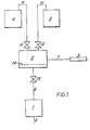
- an ejector jet pump 1 with tubing 6 is connected to a material collection container 2. This is connected with a flexible catheter 3 by means of a suction tube 7. Tubing 8 is used for discharge of waste water from pump 1.
- a washing liquid container 4 is connected to the collection container 2 by means of tubing 9, and a fixing liquid container 5 by means of tubing 10.
- the lengths of tubing 9, 10 and 6 are provided with valves 11, 12 and 13 respectively.
- the endometrium is removable, e.g. in the course of interruption of pregnancy.
- the sucked material passes through suction tube 7 into the collection container 2, where the washing liquid washes out the blood, while the tissue particles get caught on a built-in replaceable filter 14, and are thus withheld.
- the blood-laden washing water passes continuously through tubing 6, ejector jet pump 1 and tubing 8 into a sewage canal.
- the quantity and time of applying the washing liquid and fixing liquid may be chosen at discretion.
- the tissue parts e.g. necessary for histological examination, separated from the blood, washed and fixed, are removable from the collection container 2.
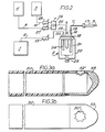
- FIG. 2 shows a possible structural design of the collection container 2 with the connected units.
- Catheter 3 is connected through suction tube 7 to stub 16 of the collection container 2.
- the catheter can be passed through the hole of a guide tube 17 and preferably fixed in it.
- a cover 18 of the collection container 2 is provided with a suspension element 29 for holding up the container.
- Connecting tube stubs 16, 19 and 20 are provided on cover 18.
- a transparent vessel 21 of the container 2, and cover 18, are locked airtight with a clamping element 23 of a fixing device 22.
- a bag-like filter insert 24 is provided on an extension of tube stub 20, reaching into the interior of vessel 21.
- Tubing 25 is connected to tube stub 19, leading to the outlet of a selector valve 26.
- Tubing 9, provided with a choke valve 27, is connected to one of the inlets of selector valve 26, the other end of the tubing 9 being connected to the washing liquid container 4.
- Tubing 10, provided with a choke valve 28, leading from fixing liquid container 5, is connected to the other inlet of selector valve 26.
- Tubing 6 provided with a valve 13 is connected to the tube stub 20 and leads to the ejector jet pump 1.
- Ejector jet pump 1 brings about vacuum in the collection container 2, through tubing 6 at open position of valve 13.
- a quantity of the fixing liquid -set by choke valve 28-flows from the fixing liquid container 5 into the container 2 At the same time, at suction openings in the distal end of catheter 3 a suction effect develops, the magnitude depending on the positions of valves 13,. 27, 28 and 26. Removal of the contents of a cavity takes place with the help of this suction effect in the course of operation with the apparatus as described by way of an example as follows.
- the distal end of the guide tube 17 is introduced into the cervix. This is followed by passing catheter 3 through the hole of guide tube 17 and by removal of the contents of the uterus.
- the materials sucked out of the cavity pass through tube stub 16 into the washing- treating container 2, from where the liquid parts e.g. blood as a result of the continuous washing depart through tube stub 20, whilst the other parts e.g. tissues necessary for further examination, remain in vessel 21.
- introduction of the washing liquid takes place simultaneously with removal of the contents of the uterus, while application of the fixing liquid may take place at the end of the removal, immediately after washing.
- the washed and fixed material may be stored in vessel 21 after releasing the clamping element 23.
- Vessel 21 can be closed with a closure element, suitably with a stopper.
- the suction openings at the end of the suction catheter to be introduced into the cavity are provided with a knife-like edge.
- the catheter is made from polyethylene tube and its end to be introduced into the cavity is hardened by a chemical process, e.g. by soaking in benzene, i.e. by dissolving the softeners.
- the sharp-edged suction opening is provided by the hardened material part.
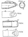
- a metal insert 32 is placed into a lateral suction opening of a flexible catheter tube 31, at the end of which a sharp orifice edge is thus developed, reaching to the periphery of the tube 31.
- the end of a flexible catheter tube 30 to be introduced into the cavity has a tip 33, say 1 to 3 cm long, made from metal, and the lateral suction opening 32' is provided in this tip.
- a tip 33 say 1 to 3 cm long, made from metal, and the lateral suction opening 32' is provided in this tip.
- a similar construction is shown in Fig. 5a and 5b, with a flexible catheter tube 31' being provided with a metal tip 33'.
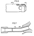
- Figure 6 shows a further design of a catheter in accordance with the invention.
- a metal brush 34 is fixed in the open end of a flexible catheter tube 31".
- the metal bush 34 and thus the catheter too, is open in axial direction. Lateral openings are also provided.
- the suction catheter is closed in axial direction and is asymmetrically rounded.
- the provision of asymmetrical rounding means that centreline of the catheter tube and that of the rounding do not coincide.
- the enveloping surface of the rounding may be a surface of rotation, e.g. spherical surface.
- One form of the asymmetrical rounding can be seen in Figure 4a. In this arrangement the catheter tube ends in a sphere of radius R, arranged with eccentricity e with respect to the axis A of tube 31. Another example of asymmetrical rounding is seen in Figures 3a and 3b. In this arrangement the metal end 33 is rounded asymmetrically.
- the catheter is preferably also provided with a guide tube.
- the guide tube 17 is used for introducing the catheter 3 into the cavity.
- the shape and size of the aperture extending the length of the guide tube 17 is such as to suit the shape and size of the suction catheter, so that the suction catheter can be easily passed through the guide tube.
- the external form at one end of the guide tube suits the shape and size of the cavity entrance, while the axial passage at the other end is preferably tapered, and its external shape may be handle-like.
- the guide tube can be seen clearly in Figure 7.
- One end 36 of the guide tube 17 fits into the cavity entrance 35.
- the catheter can be led easily into the cavity through the passage in the guide tube 17 in such a way that movement of the suction catheter is not prevented by the spontaneous contraction of the cavity entrance, without the risk of injury.
- Use of the guide tube is very advantageous in gynaecological practice.
- the proximal end of the guide tube passage is tapered, to assist feeding of the catheter.
- the guide tube is introduced preferably only up the inner orifice of the uterus, and may be straight or slightly bent in respect of its cehtre- line.
- Figure 7 shows a bent guide tube.
- Figures 8a, b and c show another embodiment of a catheter 131 and a guide tube 37.
- a lock pin 38 is provided in a thickened part of guide tube 37. In one position of the lock pin as shown in Fig. 8b the catheter 131 can be freely moved in the guide tube. By turning the lock pin 38 to the position shown in Fig. 8c the catheter tube 131 can be fixed in guide tube 37.
- the catheter tube 131 is provided with metal tip 39 at its end to be led into the cavity.
- FIG. 8 shows such an application.
- the catheter fixed with lock pin 38 in guide tube 37, in the course of its introduction into cervix 40 separates valuable examination material from the endoceruix.
- catheter tube 131 is releasable and the operation, with or without a catheter change, can be continued with the same apparatus without interruption.
- the visible part of the outer mantle outside the cavity entrance is provided with marks, e.g. notches with numerical symbols - in order to facilitate estimation of the position of the distal end of the guide tube and the inner orifice of the uterus in relation to each other.
Landscapes
- Health & Medical Sciences (AREA)
- Heart & Thoracic Surgery (AREA)
- Life Sciences & Earth Sciences (AREA)
- General Health & Medical Sciences (AREA)
- Animal Behavior & Ethology (AREA)
- Engineering & Computer Science (AREA)
- Veterinary Medicine (AREA)
- Public Health (AREA)
- Biomedical Technology (AREA)
- Surgery (AREA)
- Pathology (AREA)
- Molecular Biology (AREA)
- Medical Informatics (AREA)
- Vascular Medicine (AREA)
- Anesthesiology (AREA)
- Hematology (AREA)
- Gynecology & Obstetrics (AREA)
- Reproductive Health (AREA)
- Surgical Instruments (AREA)
- Media Introduction/Drainage Providing Device (AREA)
- Infusion, Injection, And Reservoir Apparatuses (AREA)
Description
- This invention relates to the removal of material from body cavities by suction. Such removal is effected by means of a vacuum suction unit, a catheter, and a container disposed therebetween, the container including a filter.
- Removal of material from body cavities is well known in medical practice, and a number of apparatuses have been proposed. United Kingdom Patent 1,273,387 for example discloses an instrument intended mainly for gynaecological purposes, and including a catheter connected to a container provided with a filter which container serves also as a handle for the instrument.
- A problem with such apparatus is that the material drawn from the cavity cannot be directly observed. Due to the fast rate of coagulation, tissue portions and clotted blood or other unnecessary material cannot be efficiently separated, in spite of the provision of a filter. Furthermore, no provision is made for the fixing and disinfection of tissue portions, preferably with formalin, which is necessary for subsequent, e.g. microscopic, examination.
- In U.S. Patent 3,929,133 there is proposed apparatus for use in the removal of material from body cavities by suction, comprising a catheter, a suction unit, and a collection container disposed between the catheter and the suction unit, said container being provided with a filter in the flow path between the catheter and suction unit and being connectable to a source of liquid for washing the material collected in the container.
- With such an arrangement, besides filtering of biopsy material obtained from the cavity there is possible its examination by eye, and its washing for immediate examination. This is of use, especially in gynaecology where careful inspection of the removed endometrium may influence decisively the further course of an operation. The immediate washing of withdrawn material is desirable for such inspection. Direction of the further examination of the removed material could be decided in the course of such visual evaluation. For this purpose the continuous and immediate removal of material such as blood which would interfere with the evaluation, is advantageous.
- It is desirable not only to wash the material, but to treat it, e.g. to preserve the structure of the material to be examined, as soon as possible. Removal of material from a cavity generally involves substantial bleeding. Thus a major part of the extracted material is blood, disturbing examination of the cells and tissue portions, or. even making it impossible. With known apparatus and techniques it has been the case that a significant part of the extracted material is not available for detailed examination. Whilst an arrangement of U.S. Patent 3,929,133 permits visual examination, any more detailed examination would involve removal of the material from the container.
- According to the invention therefore, there is provided apparatus for use in the removal of material from body cavities by suction, comprising a catheter, a suction unit, and a collection container disposed between the catheter and the suction unit, said container being provided with a filter in the flow path between the catheter and suction unit and being connectable to a source of liquid for washing the material collected in the container, wherein there are further provided a source of liquid for treating the material collected in the collection container and valves for selectively coupling the two sources to the collection container.
- The sources of fluid may be in the form of liquid containers connected to the collection container by means of a regulating and locking device. The collection container may consist of a cover provided with connecting elements, and a replaceable vessel provided with closing means usable after the vessel has been detached from the cover. At least the vessel may be disposable after use, being of e.g. plastics.
- The collection container may be at least partly of transparent material and is advantageously provided with a bag-like filter insert suitably connected to the cover.
- According to another aspect of the invention there is provided a method of washing and treating material removed from a cavity by suction, using the above apparatus.
- By means of apparatus or a method in accordance with the invention, there is possible not only the continuous washing and filtering of material extracted from a body cavity by suction, so that the parts necessary for further examination can be separated in the suction apparatus itself without being damaged, and can be visually evaluated, but also treatment with a suitable liquid so that they can be prepared for further examination.
- By providing for treatment with various liquids, the apparatus is suitable for preparation, fixing, disinfection, dying of examination material, or for preparation of cytochemical, histochemical, ultramicroscopic, or autoradiographic examinations etc. A further advantage is that by enabling rapid fixing if required autolysis of cell organelles is preventible.
- Referring to the apparatus disclosed in U.S. Patent No. 3,721,244, a drawback - besides those already mentioned - is that the catheter is not replaceable at all. A further disadvantage is that for instance in case of interruption of pregnancy, in the interest of easy manipulation with the instrument the cervix should previously be dilated in relation to the diameter of the catheter.
- In general, little consideration is given to the necessity of careful treatment of the cervix; replacement of a catheter during operation is not possible, or is difficult to achieve; and simultaneous-for instance cytological-sample taking is not possible in the course of the operation.
- Highly significant among known suction catheters are those which are used for intrauterine interventions in gynaecology. Medical practice has special requirements concerning gynaecological suction catheters. The form of the end of the suction catheter should enable one to pass a catheter of necessary thickness through the cervix after minimal dilation and without any injury thereof. Injury of the cervix is very frequent, causing premature births, subsequent sterility and cancerous diseases. At the same time, for removal of more persistently sticking materials it is advisable to use rigid edge-like forms in such an arrangement by which the removal of endometrium persistently adhering to the rear wall of the uterus, can also be ensured. At the same time it would be essential, that the suction catheter should not cause injury, e.g. perforation of the uterus. In this respect the above described solutions are not entirely satisfactory.
- Thus it is apparent that known rigid suction catheters leave many problems unsolved. Although the possibility of edge development is provided with instruments made from metal, the rigidity of the catheter frequently leads to injury of the uterus. For this reason flexible suction catheters, such as for instance the flexible catheter disclosed in US Patent No. 3,506,010 have become widely popular. These catheters considerably reduce the risk of injury, but their flexible material does not allow the rigid edge development, and thus they are not suitable for sample taking, or for the removal of persistently sticking materials. In U.S. Patent 3,774,612 there is disclosed a flexible catheter having a rigid end piece, but the tip of this is deliberately thinned to make it flexible and soft. Thus this arrangement does not solve the problem either.
- Thus in an embodiment of the present invention there is provided a catheter which permits the removal of persistently sticking material particles, similarly to the method carried out with a curette scoop, and at the same time makes the excessive dilation of the cavity entrance avoidable and reduces the risk of injury. Thus there is used a flexible catheter in which the or each suction opening is surrounded at least in part by rigid material providing a hard edge.
- In flexible plastics suction catheters the material surrounding the suction opening can be made rigid by known physical or chemical processes. Surrounding the suction opening with rigid material can also be provided by making the end of the suction catheter from metal. There are also possible arrangements in which only the parts surrounding the suction opening are formed as as an insert made from metal, or other rigid material.
- In case of a suction catheter with a closed distal end, the end part, i.e. the end to be entered into the cavity, is preferably rounded asymmetrically.
- In apparatus in accordance with the invention the catheter is preferably provided with a guide tube, its distal end positionable in the entrance of the cavity, so as to facilitate the penetration of the suction catheter into, and its controlled movement within, the cavity. The proximal end of the guide tube is preferably formed in such a way, that its moving and fixing are simple and safe.
- The guide tube may consist of several parts fixed to each other, and furthermore it may be releasably fixed to the suction catheter.
- The outer part of the guide tube may be provided with a handle and with position marks referring to the position in relation to the cavity entrance.
- In apparatus in accordance with the invention the catheter is preferably not connected directly to the collection container, but via a suction tube. The use of a flexible suction tube is very advantageous in respect of free movement and feeling with the catheter.
- The catheter side of the suction tube is preferably provided with a known connecting part, to which the catheter is simply connectable and thus easily replaceable.
- The development of the catheter end as described above ensures that in the course of its introduction into the cavity, the risk of injury to the cavity entrance is minimal. The guide tube for introducing the catheter into the cavity also reduces the risk of damaging the cavity entrance. By its use, excessive dilation of the cervix is avoidable. Without use of the guide tube the cervix has to be considerably dilated, partly to provide easier manipulation and partly because of spontaneous contraction during operation. A further advantage is that by using the guide tube, material can be obtained from the cavity of the uterus without the injury of the hymen.
- In this way the flexible catheter described above considerably reduces the injury of the cavity because of its flexibility, and at the same time with the aid of the suction openings provided with hard edges, the contents of the cavity including persistently sticking materials are easily removable.
- In many cases, e.g. in gynaecological practice, on removal of the contents of the uterus, it is an important aspect, that no removable material should remain in the cavity. This requirement is met by the flexible catheter described above by simultaneously ensuring the removal of material with the suction hc!es provided with cutting edges, and its evacuation by the aid of the suction effect.
- The advantage of an asymmetrically rounded catheter end is significant in its gynaecological application.
- With this development, in the course of passing the catheter through the cervix, by turning the suction catheter while it is being pushed in, the risk of injuring the inner orifice of the uterus is considerably reduced.
- The reason for this is found in the fact, that the inner orifice of the uterus is situated asymmetrically in relation to the line of the cervix, and thus with the asymmetrically rounded end of the suction catheter, the orifice of the inner uterus can be found when it is pushed in, the lip of the inner orifice is not in frontal contact with the catheter-end.
- The asymmetrically rounded cather-end provides advantages in the case of other cavity entrances also, since by turning the cather, its end moves concentrically, thereby considerably facilitating the progress in the cavity entrance.
- Some embodiments of the invention will now be described by way of example and with reference to the accompanying drawings, in which:-
- Figure 1 is a schematic diagram of apparatus in accordance with the invention;
- Figure 2 is a more detailed, schematic illustration of the apparatus shown in Fig. 1;
- Figure 3a is a section of a catheter in accordance with the invention;
- Figure 3b is a plan view of the catheter of Fig. 3a;
- Figure 4a is a longitudinal section through another embodiment of a catheter in accordance with the invention;
- Figure 4b is a transverse section through the catheter of Fig. 4a;
- Figure 4c is a plan view of the catheter of Figs. 4a and 4b;
- Figure 5a is a longitudinal section through a further embodiment of a catheter in accordance with the invention;
- Figure 5b is a plan view of the catheter of Fig. 5a;
- Figure 6 is a plan view of another catheter in accordance with the invention, partially in section;
- Figure 7 shows a section through a guide tube for use with apparatus in accordance with the invention whilst being in use;
- Figure 8a is a longitudinal section through another guide tube and catheter in accordance with the invention whilst being in use; and Figures 8b and 8c are two transverse sections through the arrangement of Fig. 8a.
- Referring to Figure 1, an
ejector jet pump 1 withtubing 6 is connected to amaterial collection container 2. This is connected with aflexible catheter 3 by means of asuction tube 7. Tubing 8 is used for discharge of waste water frompump 1. - A washing
liquid container 4 is connected to thecollection container 2 by means oftubing 9, and a fixingliquid container 5 by means oftubing 10. The lengths oftubing valves - Operation of the apparatus is as follows-
Ejector jet pump 1, withvalve 13 at the open position, brings about a vacuum in thecollection container 2. As a result of the vacuum, a suction effect develops at the suction openings ofcatheter 3, and depending on the positions of thevalves containers collection container 2. The arrangement ofcontainers collection container 2, and thus the flow of liquid will occur only in case of vacuum. - By introducing a
catheter 3 into the uterus, the endometrium is removable, e.g. in the course of interruption of pregnancy. The sucked material passes throughsuction tube 7 into thecollection container 2, where the washing liquid washes out the blood, while the tissue particles get caught on a built-inreplaceable filter 14, and are thus withheld. The blood-laden washing water passes continuously throughtubing 6,ejector jet pump 1 and tubing 8 into a sewage canal. The quantity and time of applying the washing liquid and fixing liquid may be chosen at discretion. After completion of the operation, the tissue parts, e.g. necessary for histological examination, separated from the blood, washed and fixed, are removable from thecollection container 2. - Figure 2 shows a possible structural design of the
collection container 2 with the connected units.Catheter 3 is connected throughsuction tube 7 to stub 16 of thecollection container 2. The catheter can be passed through the hole of a guide tube 17 and preferably fixed in it. Acover 18 of thecollection container 2 is provided with asuspension element 29 for holding up the container. Connecting tube stubs 16, 19 and 20 are provided oncover 18. Atransparent vessel 21 of thecontainer 2, and cover 18, are locked airtight with a clampingelement 23 of a fixingdevice 22. A bag-like filter insert 24 is provided on an extension oftube stub 20, reaching into the interior ofvessel 21.Tubing 25 is connected totube stub 19, leading to the outlet of aselector valve 26.Tubing 9, provided with achoke valve 27, is connected to one of the inlets ofselector valve 26, the other end of thetubing 9 being connected to the washingliquid container 4.Tubing 10, provided with achoke valve 28, leading from fixingliquid container 5, is connected to the other inlet ofselector valve 26.Tubing 6 provided with avalve 13 is connected to thetube stub 20 and leads to theejector jet pump 1. -
Ejector jet pump 1 brings about vacuum in thecollection container 2, throughtubing 6 at open position ofvalve 13. As a result of the vacuum, at one of the open positions of the selector valve 26 a quantity of the washing liquid-set by choke valve 27-flows from the washingliquid container 4 throughtubing 25 intocontainer 2, and at the other open position a quantity of the fixing liquid -set by choke valve 28-flows from the fixingliquid container 5 into thecontainer 2. At the same time, at suction openings in the distal end of catheter 3 a suction effect develops, the magnitude depending on the positions ofvalves 13,. 27, 28 and 26. Removal of the contents of a cavity takes place with the help of this suction effect in the course of operation with the apparatus as described by way of an example as follows. - The distal end of the guide tube 17 is introduced into the cervix. This is followed by passing
catheter 3 through the hole of guide tube 17 and by removal of the contents of the uterus. The materials sucked out of the cavity pass throughtube stub 16 into the washing- treatingcontainer 2, from where the liquid parts e.g. blood as a result of the continuous washing depart throughtube stub 20, whilst the other parts e.g. tissues necessary for further examination, remain invessel 21. Thus introduction of the washing liquid takes place simultaneously with removal of the contents of the uterus, while application of the fixing liquid may take place at the end of the removal, immediately after washing. The washed and fixed material may be stored invessel 21 after releasing the clampingelement 23.Vessel 21 can be closed with a closure element, suitably with a stopper. - The suction openings at the end of the suction catheter to be introduced into the cavity are provided with a knife-like edge. This can be attained in several ways. According to a preferred design the catheter is made from polyethylene tube and its end to be introduced into the cavity is hardened by a chemical process, e.g. by soaking in benzene, i.e. by dissolving the softeners. The sharp-edged suction opening is provided by the hardened material part.
- In one preferred embodiment of a structural design of catheter in accordance with the invention as shown in Figures 4a, b and c, a
metal insert 32 is placed into a lateral suction opening of aflexible catheter tube 31, at the end of which a sharp orifice edge is thus developed, reaching to the periphery of thetube 31. - In a further embodiment shown in Figure 3a and 3b, the end of a
flexible catheter tube 30 to be introduced into the cavity, has atip 33, say 1 to 3 cm long, made from metal, and the lateral suction opening 32' is provided in this tip. A similar construction is shown in Fig. 5a and 5b, with a flexible catheter tube 31' being provided with a metal tip 33'. - Figure 6 shows a further design of a catheter in accordance with the invention. Here a
metal brush 34 is fixed in the open end of aflexible catheter tube 31". - In this arrangement the
metal bush 34, and thus the catheter too, is open in axial direction. Lateral openings are also provided. - According to a preferred embodiment of the invention, the suction catheter is closed in axial direction and is asymmetrically rounded. The provision of asymmetrical rounding means that centreline of the catheter tube and that of the rounding do not coincide. The enveloping surface of the rounding may be a surface of rotation, e.g. spherical surface. One form of the asymmetrical rounding can be seen in Figure 4a. In this arrangement the catheter tube ends in a sphere of radius R, arranged with eccentricity e with respect to the axis A of
tube 31. Another example of asymmetrical rounding is seen in Figures 3a and 3b. In this arrangement themetal end 33 is rounded asymmetrically. - The catheter is preferably also provided with a guide tube. The guide tube 17 is used for introducing the
catheter 3 into the cavity. The shape and size of the aperture extending the length of the guide tube 17 is such as to suit the shape and size of the suction catheter, so that the suction catheter can be easily passed through the guide tube. The external form at one end of the guide tube suits the shape and size of the cavity entrance, while the axial passage at the other end is preferably tapered, and its external shape may be handle-like. The guide tube can be seen clearly in Figure 7. Oneend 36 of the guide tube 17 fits into thecavity entrance 35. The catheter can be led easily into the cavity through the passage in the guide tube 17 in such a way that movement of the suction catheter is not prevented by the spontaneous contraction of the cavity entrance, without the risk of injury. Use of the guide tube is very advantageous in gynaecological practice. As can be seen, the proximal end of the guide tube passage is tapered, to assist feeding of the catheter. - The guide tube is introduced preferably only up the inner orifice of the uterus, and may be straight or slightly bent in respect of its cehtre- line. Figure 7 shows a bent guide tube. Figures 8a, b and c show another embodiment of a
catheter 131 and aguide tube 37. Alock pin 38 is provided in a thickened part ofguide tube 37. In one position of the lock pin as shown in Fig. 8b thecatheter 131 can be freely moved in the guide tube. By turning thelock pin 38 to the position shown in Fig. 8c thecatheter tube 131 can be fixed inguide tube 37. Thecatheter tube 131 is provided withmetal tip 39 at its end to be led into the cavity. - This catheter development is especially suitable in gynaecology for taking samples from the cervical canal. Figure 8 shows such an application. The catheter, fixed with
lock pin 38 inguide tube 37, in the course of its introduction intocervix 40 separates valuable examination material from the endoceruix. By turning thelock pin 38,catheter tube 131 is releasable and the operation, with or without a catheter change, can be continued with the same apparatus without interruption. In a preferable structural design of the guide tube, the visible part of the outer mantle outside the cavity entrance is provided with marks, e.g. notches with numerical symbols - in order to facilitate estimation of the position of the distal end of the guide tube and the inner orifice of the uterus in relation to each other.
Claims (12)
Applications Claiming Priority (2)
| Application Number | Priority Date | Filing Date | Title |
|---|---|---|---|
| HUDO000416 | 1977-10-24 | ||
| HU77DO416A HU179954B (en) | 1977-10-24 | 1977-10-24 | Process and equipment further catheter for the elimination by suction of the content of body cavities and/or simultaneous sampling by operation |
Publications (2)
| Publication Number | Publication Date |
|---|---|
| EP0001718A1 EP0001718A1 (en) | 1979-05-02 |
| EP0001718B1 true EP0001718B1 (en) | 1982-01-20 |
Family
ID=10995020
Family Applications (1)
| Application Number | Title | Priority Date | Filing Date |
|---|---|---|---|
| EP78300537A Expired EP0001718B1 (en) | 1977-10-24 | 1978-10-24 | Apparatus and method for use in the removal of material from body cavities by suction |
Country Status (7)
| Country | Link |
|---|---|
| US (1) | US4250892A (en) |
| EP (1) | EP0001718B1 (en) |
| JP (1) | JPS5929261B2 (en) |
| DE (1) | DE2861555D1 (en) |
| HU (1) | HU179954B (en) |
| IT (1) | IT1192333B (en) |
| SU (1) | SU784737A3 (en) |
Families Citing this family (32)
| Publication number | Priority date | Publication date | Assignee | Title |
|---|---|---|---|---|
| US4257425A (en) * | 1979-06-04 | 1981-03-24 | Codman & Shurtleff, Inc. | Biopsy specimen collector |
| WO1989005612A1 (en) * | 1987-12-24 | 1989-06-29 | Sumitomo Bakelite Company Limited | Excreting apparatus |
| JPH0532094Y2 (en) * | 1988-05-17 | 1993-08-18 | ||
| JPH0611309B2 (en) * | 1991-05-28 | 1994-02-16 | 克弥 高須 | Collagen collection device |
| JPH0636813B2 (en) * | 1992-04-17 | 1994-05-18 | 大研医器株式会社 | Treatment method and treatment container for waste liquid containing body fluid |
| US5282820A (en) * | 1992-11-03 | 1994-02-01 | Goodstein Wallace A | Liposculpture device and method |
| US5357977A (en) * | 1993-04-23 | 1994-10-25 | St. Mary's Hospital And Medical Center, Inc. | Cytological sampling method and device |
| DE69534405T2 (en) * | 1994-07-01 | 2006-03-09 | Edwards Lifesciences Corp., Irvine | APPARATUS FOR OBTAINING AUTOMATED, MICROVASCULAR ENDOTHELIAL CELLS CONTAINING FAT TISSUE |
| CA2199864C (en) * | 1994-09-16 | 2006-06-20 | Seth A. Foerster | Methods and devices for defining and marking tissue |
| US6020196A (en) * | 1996-05-09 | 2000-02-01 | Baxter International Inc. | Devices for harvesting and homogenizing adipose tissue containing autologous endothelial cells |
| JP3327145B2 (en) * | 1996-11-06 | 2002-09-24 | 双葉電子工業株式会社 | Fuel injection device for model engine |
| GB2323288B (en) * | 1997-04-11 | 1999-02-24 | Vacsax Limited | Apparatus for separating tissue from aspirates |
| IL122792A0 (en) * | 1997-12-29 | 1998-08-16 | T C T Products Ltd | Suction tissue collecting device |
| US6007497A (en) * | 1998-06-30 | 1999-12-28 | Ethicon Endo-Surgery, Inc. | Surgical biopsy device |
| US20010047183A1 (en) * | 2000-04-05 | 2001-11-29 | Salvatore Privitera | Surgical device for the collection of soft tissue |
| CA2287087C (en) | 1998-10-23 | 2007-12-04 | Ethicon Endo-Surgery, Inc. | Surgical device for the collection of soft tissue |
| US20080146965A1 (en) * | 2003-08-11 | 2008-06-19 | Salvatore Privitera | Surgical Device for The Collection of Soft Tissue |
| US6120462A (en) * | 1999-03-31 | 2000-09-19 | Ethicon Endo-Surgery, Inc. | Control method for an automated surgical biopsy device |
| US6086544A (en) * | 1999-03-31 | 2000-07-11 | Ethicon Endo-Surgery, Inc. | Control apparatus for an automated surgical biopsy device |
| RU2183102C1 (en) * | 2001-01-09 | 2002-06-10 | Гибадуллин Алик Халилевич | Endoscopic device for removing gallstones and foreign bodies from the hollow organs |
| US6942627B2 (en) * | 2001-07-19 | 2005-09-13 | Ethicon Endo-Surgery, Inc. | Surgical biopsy device having a flexible cutter |
| US7488312B2 (en) * | 2005-02-23 | 2009-02-10 | Rogers Joann E | Polyp screen |
| US20060265076A1 (en) * | 2005-05-03 | 2006-11-23 | Disc Dynamics, Inc. | Catheter holder for spinal implant |
| US8317725B2 (en) | 2005-08-05 | 2012-11-27 | Senorx, Inc. | Biopsy device with fluid delivery to tissue specimens |
| US7572236B2 (en) * | 2005-08-05 | 2009-08-11 | Senorx, Inc. | Biopsy device with fluid delivery to tissue specimens |
| US20080294270A1 (en) * | 2007-05-24 | 2008-11-27 | Zimmer Orthobiologics, Inc. | Differentially processed tissue and processing methods thereof |
| US20090062690A1 (en) * | 2007-08-29 | 2009-03-05 | Quaternion Investments Llc | Specimen Collecting |
| USD588695S1 (en) | 2007-08-29 | 2009-03-17 | Quaternion Investments Llc | Vaginal instrument |
| US8801725B2 (en) * | 2008-03-10 | 2014-08-12 | Zimmer Orthobiologics, Inc. | Instruments and methods used when repairing a defect on a tissue surface |
| US8603049B2 (en) * | 2008-12-15 | 2013-12-10 | Kimberly-Clark Worldwide, Inc. | Atraumatic suction catheter |
| US9113916B2 (en) | 2010-08-31 | 2015-08-25 | Zimmer, Inc. | Drill bit for osteochondral drilling with guiding element and uses thereof |
| US8435305B2 (en) | 2010-08-31 | 2013-05-07 | Zimmer, Inc. | Osteochondral graft delivery device and uses thereof |
Family Cites Families (21)
| Publication number | Priority date | Publication date | Assignee | Title |
|---|---|---|---|---|
| US2715899A (en) * | 1952-11-21 | 1955-08-23 | Maclean Kenneth Sheldon | Curette |
| US3506010A (en) * | 1968-01-29 | 1970-04-14 | Berkeley Tonometer Co | Uterine evacuator |
| US3542031A (en) * | 1968-06-24 | 1970-11-24 | Marshall B Taylor | Vacuum curette |
| DK119221B (en) * | 1968-09-17 | 1970-11-30 | Gram H | Exhaust device for body cavities. |
| DE6903004U (en) * | 1969-01-27 | 1970-07-09 | Mebeda Fa | INSTRUMENT FOR INTRAUTE TREATMENT. |
| US3670732A (en) * | 1970-05-11 | 1972-06-20 | Ralph R Robinson | Vacuum curette |
| US3721244A (en) * | 1971-01-28 | 1973-03-20 | Solly Scheiner | Manual suction curettage instruments |
| US3774612A (en) * | 1971-06-14 | 1973-11-27 | J Marco | Uterine evacuation assembly |
| US3769980A (en) * | 1971-06-28 | 1973-11-06 | Medical Concepts Inc | Medical instruments |
| DE7203913U (en) * | 1972-02-03 | 1972-05-04 | Klimek W | CUEVETTE FOR INTRAUTERINE EVACUATION |
| US3833000A (en) * | 1972-06-02 | 1974-09-03 | H Bridgman | Medical aspiration system |
| US3877464A (en) * | 1972-06-07 | 1975-04-15 | Andrew R Vermes | Intra-uterine biopsy apparatus |
| US3777743A (en) * | 1972-09-29 | 1973-12-11 | Kendall & Co | Endometrial sampler |
| DK132690C (en) * | 1973-06-15 | 1976-06-21 | H Gram | ASPIRATION CURETTE |
| JPS5215115Y2 (en) * | 1973-11-29 | 1977-04-05 | ||
| DD116393A1 (en) * | 1974-10-16 | 1975-11-20 | ||
| DE2552378C3 (en) * | 1974-11-13 | 1978-06-01 | Hans-Joachim Dr.Med. 2000 Hamburg Lindemann | Medical dilator |
| US3929133A (en) * | 1974-11-20 | 1975-12-30 | Int Pregnancy Advisory Service | Apparatus for removing, washing and displaying fragmentary products of operative procedures |
| US4050466A (en) * | 1975-10-08 | 1977-09-27 | Koerbacher Kathleen C | Endotracheal tube |
| US4036232A (en) * | 1976-04-19 | 1977-07-19 | Abbott Laboratories | Aspiration device |
| US4055167A (en) * | 1976-04-23 | 1977-10-25 | Bernstein Dell L | Curettement device |
-
1977
- 1977-10-24 HU HU77DO416A patent/HU179954B/en unknown
-
1978
- 1978-10-10 SU SU782681703A patent/SU784737A3/en active
- 1978-10-23 US US05/953,614 patent/US4250892A/en not_active Expired - Lifetime
- 1978-10-24 JP JP53130949A patent/JPS5929261B2/en not_active Expired
- 1978-10-24 IT IT6943478A patent/IT1192333B/en active
- 1978-10-24 EP EP78300537A patent/EP0001718B1/en not_active Expired
- 1978-10-24 DE DE7878300537T patent/DE2861555D1/en not_active Expired
Also Published As
| Publication number | Publication date |
|---|---|
| JPS5929261B2 (en) | 1984-07-19 |
| US4250892A (en) | 1981-02-17 |
| IT7869434A0 (en) | 1978-10-24 |
| JPS54102082A (en) | 1979-08-11 |
| SU784737A3 (en) | 1980-11-30 |
| HU179954B (en) | 1983-01-28 |
| DE2861555D1 (en) | 1982-03-04 |
| IT1192333B (en) | 1988-03-31 |
| EP0001718A1 (en) | 1979-05-02 |
Similar Documents
| Publication | Publication Date | Title |
|---|---|---|
| EP0001718B1 (en) | Apparatus and method for use in the removal of material from body cavities by suction | |
| CN112804948B (en) | Apparatus and method for biopsy and cytologically examined uterine everting catheters | |
| US4311140A (en) | Vacuum curet having an improved curetting opening | |
| US3661144A (en) | Suction apparatus for body cavities | |
| US4340066A (en) | Medical device for collecting a body sample | |
| US3955579A (en) | Vacuum curet | |
| DE69329773T2 (en) | DEVICE FOR OBTAINING ARTERIAL BIOPSIA | |
| US3929133A (en) | Apparatus for removing, washing and displaying fragmentary products of operative procedures | |
| US7344506B2 (en) | Cell collection device | |
| CA1335555C (en) | Device for collecting biological material | |
| US11266809B2 (en) | Flushable catheter device | |
| US3527203A (en) | Apparatus for circulating a fluid within a body cavity | |
| US5147335A (en) | Transurethrovesical biopsy, amniocentesis and biological sampling guide | |
| JPH11502728A (en) | Suction needle and method | |
| JP4643097B2 (en) | Physiological sampling device | |
| US6905458B2 (en) | Echogenic or radio opaque device for removal from or transfer into the genital organs | |
| CA2229337A1 (en) | Nasopharyngeal wash collection device | |
| US5135481A (en) | Ophthamalic cannula | |
| HU205557B (en) | Device for collecting aspiratum | |
| US5464022A (en) | Endometrial sampler | |
| CN1094749C (en) | Multi-function suction device for medical use | |
| GB1579185A (en) | Uterine high vacuum curette | |
| CN212996378U (en) | A vaginal dilator for vaginal discharge collection | |
| CN204951034U (en) | Sew up expander postpartum | |
| EP1379175B1 (en) | Devices for collecting material from a breast duct |
Legal Events
| Date | Code | Title | Description |
|---|---|---|---|
| PUAI | Public reference made under article 153(3) epc to a published international application that has entered the european phase |
Free format text: ORIGINAL CODE: 0009012 |
|
| AK | Designated contracting states |
Designated state(s): BE CH DE FR GB NL SE |
|
| 17P | Request for examination filed | ||
| GRAA | (expected) grant |
Free format text: ORIGINAL CODE: 0009210 |
|
| AK | Designated contracting states |
Designated state(s): BE CH DE FR GB NL SE |
|
| REF | Corresponds to: |
Ref document number: 2861555 Country of ref document: DE Date of ref document: 19820304 |
|
| PGFP | Annual fee paid to national office [announced via postgrant information from national office to epo] |
Ref country code: FR Payment date: 19841030 Year of fee payment: 7 |
|
| PGFP | Annual fee paid to national office [announced via postgrant information from national office to epo] |
Ref country code: CH Payment date: 19841031 Year of fee payment: 7 |
|
| PGFP | Annual fee paid to national office [announced via postgrant information from national office to epo] |
Ref country code: DE Payment date: 19841123 Year of fee payment: 7 |
|
| PGFP | Annual fee paid to national office [announced via postgrant information from national office to epo] |
Ref country code: SE Payment date: 19841231 Year of fee payment: 7 Ref country code: BE Payment date: 19841231 Year of fee payment: 7 |
|
| PGFP | Annual fee paid to national office [announced via postgrant information from national office to epo] |
Ref country code: NL Payment date: 19861031 Year of fee payment: 9 |
|
| PG25 | Lapsed in a contracting state [announced via postgrant information from national office to epo] |
Ref country code: SE Effective date: 19871025 |
|
| PG25 | Lapsed in a contracting state [announced via postgrant information from national office to epo] |
Ref country code: CH Effective date: 19871031 Ref country code: BE Effective date: 19871031 |
|
| BERE | Be: lapsed |
Owner name: CHINOIN GYOGYSZER ES VEGYESZETI TERMEKEK GYARA RT Effective date: 19871031 |
|
| PG25 | Lapsed in a contracting state [announced via postgrant information from national office to epo] |
Ref country code: NL Effective date: 19880501 |
|
| NLV4 | Nl: lapsed or anulled due to non-payment of the annual fee | ||
| GBPC | Gb: european patent ceased through non-payment of renewal fee | ||
| PG25 | Lapsed in a contracting state [announced via postgrant information from national office to epo] |
Ref country code: FR Free format text: LAPSE BECAUSE OF NON-PAYMENT OF DUE FEES Effective date: 19880630 |
|
| REG | Reference to a national code |
Ref country code: CH Ref legal event code: PL |
|
| PG25 | Lapsed in a contracting state [announced via postgrant information from national office to epo] |
Ref country code: DE Effective date: 19880701 |
|
| REG | Reference to a national code |
Ref country code: FR Ref legal event code: ST |
|
| PG25 | Lapsed in a contracting state [announced via postgrant information from national office to epo] |
Ref country code: GB Effective date: 19881117 |
|
| EUG | Se: european patent has lapsed |
Ref document number: 78300537.4 Effective date: 19880707 |
|
| PLBE | No opposition filed within time limit |
Free format text: ORIGINAL CODE: 0009261 |
|
| STAA | Information on the status of an ep patent application or granted ep patent |
Free format text: STATUS: NO OPPOSITION FILED WITHIN TIME LIMIT |