EP0001595B1 - Liquid soap dispensing system and liquid soap dispenser - Google Patents
Liquid soap dispensing system and liquid soap dispenser Download PDFInfo
- Publication number
- EP0001595B1 EP0001595B1 EP78101075A EP78101075A EP0001595B1 EP 0001595 B1 EP0001595 B1 EP 0001595B1 EP 78101075 A EP78101075 A EP 78101075A EP 78101075 A EP78101075 A EP 78101075A EP 0001595 B1 EP0001595 B1 EP 0001595B1
- Authority
- EP
- European Patent Office
- Prior art keywords
- neck
- soap
- piercing member
- container
- well
- Prior art date
- Legal status (The legal status is an assumption and is not a legal conclusion. Google has not performed a legal analysis and makes no representation as to the accuracy of the status listed.)
- Expired
Links
Images


Classifications
-
- A—HUMAN NECESSITIES
- A47—FURNITURE; DOMESTIC ARTICLES OR APPLIANCES; COFFEE MILLS; SPICE MILLS; SUCTION CLEANERS IN GENERAL
- A47K—SANITARY EQUIPMENT NOT OTHERWISE PROVIDED FOR; TOILET ACCESSORIES
- A47K5/00—Holders or dispensers for soap, toothpaste, or the like
- A47K5/06—Dispensers for soap
- A47K5/12—Dispensers for soap for liquid or pasty soap
Definitions
- the present invention relates to a liquid soap dispensing system and a soap dispenser which may be used therein.
- the present invention comprises an improvement over the soap dispensing system and soap dispenser disclosed in our prior French published application No. 2,340,074.
- the liquid soap container is refilled by inserting the neck of a plastic squeeze bottle into a well in the top wall of the container, a closure membrane across the end of the bottle neck being pierced by a solid piercing member in the well, whereupon the liquid soap could be squeezed and forced through small apertures in the bottom of the well communicating with the interior of the container.
- the squeeze bottle was sealed by a thin membrane across the outer end of the neck, where it could readily contact foreign objects during storage or shipment and handling, creating a danger of accidental puncture of the membrane and consequent leakage of the liquid soap from the squeeze bottle.
- US. Patent No. 3,970,121 discloses a refill injection bottle for refilling a pressurized spray container.
- the bottle has a neck insertable into a well on the container, the neck being plugged with a stopper which is pierced by a hollow tube in the well through which liquid would flow readily by gravity, except for the presence of a check valve in the pressurized container.
- the »well « is completely external of the container and the plug is at the outer end of the bottle neck, and is susceptible to contact by foreign objects.
- the stopper for the squeeze bottle is a relatively thick member 66, and it appears that the hollow tubular perforating member 50 might tend to core out of the stopper a small core of material which would, in turn, plug the hollow perforating member or, at the very least, seriously impede the flow of liquid soap therethrough.
- French Patent No. 2,144,301 discloses a soap dispenser or dispensing system in which a refill container has a sleeve extending within the container neck, the sleeve being closed by a membrane which is pierced by a hollow tube through which liquid would readily flow by gravity.
- a refill container has a sleeve extending within the container neck, the sleeve being closed by a membrane which is pierced by a hollow tube through which liquid would readily flow by gravity.
- U.S. Patent No. 3,970,121 there is the danger that the hollow tube would core out the membrane such that the flow of liquid soap would be seriously impeded.
- the object of the present invention is to provide an improved liquid soap dispensing system which avoids the deficiencies of prior art systems, while affording important advantages
- the present invention provides a liquid soap dispensing system comprising a soap injection cartridge containing liquid soap and having a cylindrical neck terminating at a discharge end. a closure member sealing said neck, said closure member being disposed within said neck, dispensing apparatus including a closed wall structure defining a soap container from which soap is to be dispensed, said wall structure having a refill aperture therethrough, and a hollow piercing member carried by said container and projecting outwardly therefrom and disposed in surrounding relationship to said refill aperture for entering said neck and piercing said closure member, characterized by said soap injection cartridge being squeezable by hand for placing the soap therein under pressure greater than that in said container for forcing the liquid soap through said refill aperture at a substantial rate after piercing of said closure member, as known per se, and dividing structure carried within said hollow piercing member adjacent to the outer end thereof for dividing said hollow piercing member into a plurality of channels and so as to prevent any portion of said closure member from entering and clogging said hollow pier
- the present invention also provides a liquid soap dispenser adapted for use with a squeezable soap injection cartridge containing liquid soap and having a cylindrical neck terminating at a discharge end, and a closure member disposed within and sealing said cylindrical neck, said dispenser including a closed wall structure defining a soap container from which soap is to be dispensed, said wall structure having a refill aperture therethrough, and a hollow piercing member carried by said container and projecting outwardly therefrom and disposed in surrounding relationship to said refill aperture for entering said neck and piercing said closure member, characterized by dividing structure carried within said hollow piercing member adjacent to the outer end thereof for dividing said hollow piercing member into a plurality of channels and so as to prevent any portion of said closure member from entering and clogging said hollow piercing member when pierced thereby, each of said channels being dimensioned substantially to inhibit the flow therethrough of liquid soap of the consistency to be dispensed at equal pressures at both ends of said channel.
- a liquid soap dispensing system and liquid soap dispenser wherein the piercing member is provided with dividers which inhibit the flow of liquid soap therethrough at equal - pressures inside and outside the container and which also prevent problems of coring of the refill bottle closure member when it is pierced by the piercmg member
- the soap injection cartridge neck moludes a sealing sleewe which is disposed in sealing relationship with the hollow piercing member to prevent the flow of liquid soap around the outside of the piercing member.
- a soap dispenser generally designated by the numeral 100, constructed in accordance with and embodying the features of the present invention, and mounted on the surface 51 of a wall 50.
- the soap dispenser 100 is similar to the soap dispenser 100 illustrated in our aforementioned French Application and, therefore, many structural details which are common to the two soap dispensers are omitted herein and reference may be made to the copending application for a fuller description of those details.
- the soap dispenser 100 includes a mounting bracket, generally designated by the numeral 101, which mcludes a generally flat rectangular wall 102 disposed substantially vertically in use to provide a bearing surface. Formed in the vertical wall 102 and projecting rearwardly therefrom are two substantially vertically aligned generally frustoconical embossments 104 (one shown), each having an opening extending therethrough centrally thereof for receiving a screw 55 for fastening the mounting bracket 101 to the wall 50. Integral with the wall 102 at the upper end thereof is an extension flange 106 which is inclined forwardly, and which is integral at the distal end thereof with an upwardly extending flange 107 which is substantially parallel to the wall 102. Integral with the bottom end of the wall 102 and extending forwardly therefrom substantially normal thereto is a bottom wall (not shown) disposed substantially horizontally in use and carrying a pumping mechanism (not shown), for a purpose to be described more fully below.
- the dispenser 100 also includes a soap container or housing, generally designated by the numeral 110, which is preferably formed of plastic.
- the container 110 is generally box-like in configuration, and includes a generally rectangular front wall 111, a pair of opposed side walls 112, a rear wall 113 and a rectangular bottom wall (not shown), the container 110 preferably being molded so that the walls 111-113 and the bottom wall are all formed integrally with one another.
- the container 110 is supported on the horizontal wal of the mounting bracket 101, in a manner more fully described in the aforementioned application.
- the walls of the container 110 cooperate to define therewithin a soap chamber, generally designated by the numeral 115 which, in use, is filled with liquid soap 116 to a predetermined level, such as 117.
- a pump assembly (not shown) which is engaged by one arm of a manually operated pump lever 120 for dispensing measured amounts of liquid soap from the container 110, in a manner described in detail in the aforementioned application.
- the container 110 is provided with a top wall 121 which is fixedly secured to the upper ends of the container walls 111 -113 for closing the upper end of the chamber 115.
- a top wall 121 Formed in the upper surface of the top wall 121 adjacent to the rear edge thereof is a narrow groove or recess 122.
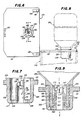
- a deep cylindrical depending well generally designated by the numeral 125, which is provided with a generally cylindrical side wall 126 having at the bottom end thereof a circular bottom wall 127.
- the well side wall 126 extends upwardly a predetermined slight distance above the upper surface of the top wall 121 to form a raised lip portion 129.
- a hollow tubular piercing member Integral with the bottom wall 127 of the well 175 and projecting upwardly therefrom substantially centrally thereof and coaxially therewith is a hollow tubular piercing member, generally designated by the numeral 130.
- the piercing member 130 has a generally cylindrical inner surface 131 which may taper slightly inwardly toward the upper end thereof, and defines a passage 132 therethrough, and a cylindrical outer surface 133 having a reduced diameter portion 134 at the upper end thereof.
- Formed within the piercing member 130 at the upper end thereof integral therewith are two flat septa or dividers 135 and 136 which intersect at right angles to each other substantially along the longitudinal axis of the piercing member 130 to form a cross which divides the upper end of the passage 132 into four channels.
- the bottom edges of the dividers 135 and 136 are disposed just above the lower ends of the reduced diameter portions 133 of the outer surface of the piercing member 130, the upper ends of the dividers 135 and 136 being flush with the top of the piercing member 130 which is inclined, as at 138, to define a sharp point 139 at the upper end thereof, the point 139 being disposed just below the top of the well side wall 126, but just above the level of the container top wall 121.
- lugs or ears 140 Integral with the top wall 121 and projecting upwardly therefrom adjacent to the front corners thereof are two lugs or ears 140, each being provided with an arcuate recess 141 defining a retaining surface in the forward edge thereof.
- a small circular retaining plate 142 Pivotally secured to the inner surface of the upwardly extending flange 107 of the mounting bracket 101, as by a rivet 143, is a small circular retaining plate 142, preferably formed of metal.
- the retaining plate 142 extends downwardly to a point adjacent to the bottom end of the inclined flange 106.
- the retaining plate 142 In use, when the container 110 is mounted on the mounting bracket 102, the retaining plate 142 is pivoted upwardly out of the way to permit the top wall 121 to pass thereunder, and then when the container rear wall 113 is against the bracket wall 102, the retaining plate 142 is pivoted back down into the groove 122 for cooperation with the mounting bracket 101 securely to hold the container 110 in place and prevent it from tipping forward.
- the dispenser 100 is also provided with a cover plate, generally designated by the numeral 145, which includes a top wall 144, a front wall 146, a pair of opposed side walls 147 and a rear wall 148, all integrally connected in a unitary structure.
- a cover plate Formed in the top wall 144 is a large bowl-like recess which serves as an ashtray substantially centrally of the cover plate 145, the top wall 144 also having formed therein between the ashtray and the front wall 146 a plurality of flutes to serve as cigarette holders.
- the cover plate 145 is dimensioned so as to completely cover the top wall 121 of the container 110, with the walls 146-148 having a depth sufficient to accomodate the inclined flange 106 and the upwardly extending flange 107 of the mounting bracket 101.
- the projections 149 are inserted into the arcuate recesses 141 of the lugs 140, and the cover plate 145 is then pivoted down into position completely covering the top of the container 110, as illustrated in Fig. 2.
- the cover plate 145 may be provided with a lock mechanism (not shown) for locking the cover plate 145 in place and protecting the well 125 from unauthorized users.
- a refill cartridge or bottle for use with the dispenser 100 to provide a complete liquid soap dispensing system.
- the refill bottle 150 is preferably in the form of a soft plastic squeeze-bottle and is adapted to hold a refill or supply of liquid soap for refilling the soap container 110 of the dispenser 100.
- the refill bottle 150 includes an elongated right circular cylindrical side wall 151 closed at one end thereof by a circular bottom wall 152, and having integrally connected thereto at the other end thereof an inwardly sloping frustoconical top wall 153 which terminates in a flat annular shoulder 154.
- a cylindrical neck Integral with the annular shoulder 154 and extending outwardly therefrom coaxially therewith is a cylindrical neck, generally designated by the numeral 155, which is substantially thicker and more rigid than the walls 151 -153, and includes a cylindrical inner surface 156 and an outer surface 157. Integral with the outer surface 157 and projecting radially outwardly therefrom are a plurality of longitudinally spaced-apart annular ribs 158, each substantially triangular in transverse cross section. Also integral with the outer surface 157 and extending radially outwardly therefrom adjacent to the outer end thereof is a short annular lead rib 158a, which is somewhat smaller than the ribs 158.
- the neck 155 terminates in an annular end surface 159.
- the neck 155 is adapted to be terminated by a plug, generally designated by the numeral 160, and preferably of the same type of plastic as the bottle 150.
- the plug 160 includes an annular body 161 provided along the upper surface thereof with a plurality of radially spacedapart annular teeth 162. Integral with the annular body 161 along the inner surface thereof and extending radially inwardly thereof is an annular inner projection 163. Integral with the projection 163 and extending axially therefrom is a cylindrical spout or sleeve 165 having along the end thereof adjacent to the annular body 161 an inner cylindrical surface 164 and an outer cylindrical surface 166.
- the outer cylindrical surface 166 joins a frustoconical outer surface 167 sloping radially inwardly toward the distal end of the sleeve 165.
- the inner cylindrical surface 164 is joined at the upper end thereof by a radially inwardly sloping shoulder 168 to a cylindrical sealing surface 169 having an inner diameter substantially the same as the outer diameter of the surface 133 of the piercing member 130 of the soap dispenser 100.
- Integral with and closing the distal end of the cylindrical sleeve 165 is a circular closure wall 170.
- Formed in the closure wall 170 along the outer periphery of the inner surface thereof is a deep annular recess 171, generally V-shaped in transverse cross section.
- the portion of the closure wall 170 at the base of the recess 171 defines a thin bridge portion 172 for a purpose to be explained more fully below.
- the cylindrical sleeve 165 of the plug 160 is inserted into the neck 155 of the bottle 150, the cylindrical outer surface 166 of the sleeve 165 having an outer diameter slightly less than the diameter of the inner cylindrical surface 156 of the neck 155.
- the teeth 162 of the plug 160 are pressed firmly into engagement with the end surface 159 of the neck 155 and the annular body 161 is then ultrasonically welded to the neck 155, the teeth 162 providing the plastic material which flows to form the weldment, indicated at 175 in Fig. 4.
- the plug 160 is thus welded in place, it seals the neck 155 and prevents escape of the liquid soap 116 from the bottle 150.
- the closure wall 170 is disposed about halfway down the neck 155 and is, therefore, protected from accidental engagement with and rupture by foreign objects in handling or storage of the bottle 150. '
- the cover plate 145 is unlocked and removed to expose the refill well 125.
- the neck 155 of the refill bottle 150 is then inserted into the well 125 of the soap container 110.
- the maximum outer diameter of the ribs 158 are substantially equal to the diameter of the inner surface of the well side wall 126 so as to be .disposed in frictional sealing engagement therewith as the neck 155 is inserted into the well 125, the ribs 158 being sufficiently resilient to permit insertion of the neck 155 all the way into the well 125 until the annular body 161 of the plug 160 contacts the bottom wall 127 of the well 125 and the shoulder 154 of the bottle 150 engages the upper surface of the raised lip portion 129 of the well 125. It will be noted that when thus fully inserted, the annular body 161 of the plug 160 overlies and closes the upper ends of the drain holes 128 in the well bottom wall 127.
- the piercing member 130 is received into the spout or sleeve 165 of the plug 160, with the projection 163 and the sealing surface 169 of the plug 160 being disposed in sliding sealing engagement with the outer surface 133 of the piercing member 130.
- the sharp point 139 of the piercing member 130 enters the annular recess 171 at the right-hand side of the closure wall 170, as viewed in Fig. 9 and pierces or cuts throught the thin bridge portion 172 at that point.
- the slanted top 138 continues to engage and cut through the bridge portion 172 around the opposite sides of the closure wall 170 until the piercing member 130 has passed entirely through the closure wall 170, as illustrated in Fig. 9.
- the liquid soap therein is placed under pressure greater than that in the container 110 and is forced through the channels formed by the dividers 135 and 136 and thus through the passage 132 in the piercing member 130 into the chamber 115 inside the container 110.
- the sealing engagement between the outer surface 133 of the piercing member 130 and the projection 163 and sealing surface 169 of the plug 160 prevent the liquid soap from flowing around the outside of the piercing member 130.
- the dividers 135 and 136 together with the thinness of the closure wall 170 and particularly the bridge portion 172 thereof, assist in pushing the flap 173 back out of the way and prevent the piercing member 130 from coring a hole through the closure wall 170.
- this arrangement prevents a loose core of material from being formed which might float free in the neck 155 or become jammed in the passage 132, in either event hindering or obstructing flow of liquid soap through the passage 132.
- the bottle 150 After the bottle 150 has been emptied, it is removed from the well 125, the sliding and sealing engagement of the inner projection 163 and sealing surface 169 of the plug 160 with the outer surface 133 of the piercing member 130 serving to wipe any residue of liquid soap from the outer surface of the piercing member 130. If, however, any liquid soap is accidentally spilled into the bottom of the well 125 around the outside of the piercing member 130, it will eventually drain through the drain holes 128 into the container 110. It will be appreciated that the formation of the well 125 extending inwardly of the container 110 prevents the escape of liquid soap from the container 110 through the drain holes 128 or the passage 132 when the container 110 is removed from the mounting bracket 101 and inverted for replacement, service or the like. In this event, any residue of liquid soap remaining in the chamber 115 will collect along the top wall 121, but normally not to a sufficient depth to cover the bottom wall 127 of the well 125.
- the refill bottle 200 is preferably in the form of a soft plastic squeeze-bottle and includes an elongated right circular cylindrical side wall 201 closed at one end thereof by a circular bottom wall 202, and having integrally connected thereto at the other end thereof an inwardly sloping frustoconical top wall 203 which terminates in an annular shoulder 204.
- a cylindrical neck Integral with the shoulder 204 and extending axially therefrom is a cylindrical neck, generally designated by the numeral 205, which is substantially thicker and more rigid than the walls 201 through 203, and includes a cylindrical inner surface 206 and an outer surface 207. Integral with the outer surface 207 and extending radially outwardly therefrom are a plurality of axially spaced-apart annular ribs 208.
- the neck 205 terminates in a thickened outer end 209.
- a circular closure web or membrane 210 having a diameter substantially the same as the diameter of the inner surface 206, is inserted into the opening through the neck 205 and it is ultrasonically welded in place effectively to close and seal the discharge outlet through the neck 205 and prevent the escape of the liquid soap 116 therefrom (see Fig. 11).
- the neck 205 is inserted into the well 125, in the same manner as was described above in connection with the refill bottle 150.
- the ribs 208 have a maximum outer diameter such that they are disposed in sliding sealing engagement with the inner surface of the well side wall 126.
- the neck 205 is inserted until the thickened end portion 209 thereof bottoms on the bottom wall 127 of the well 126, and the shoulder 204 seats against the upper surface of the raised lip portion 129 of the well 125, as illustrated in Fig. 12.
- the sharp point 139 and slanted upper edge 138 of the piercing member 130 pierces the membrane 210, thereby to permit the liquid soap to be squeezed from the bottle 200 through the passage 132 in the piercing member 130 under pressure greater than that in the container 110 to refill the chamber 115 of the container 110.
- Any liquid soap which might seep around the outside of the piercing member 130 eventually drains through the drain holes 128 after the neck 205 has been removed from the well 125. It will be appreciated that the recessed position of the web or membrane 210 within the neck 205 prevents its accidental engagement with foreign objects, and thereby prevents accidental rupture thereof and leaking of the contents of the bottle 200.
- the mounting bracket 101 and the cover plate 145 are preferably formed of metal; the soap container 130 is preferably formed of transparent plastic, and the injection bottles 150 and 200 are preferably formed of a translucent plastic material.
- the soap container 130 is preferably formed of transparent plastic
- the injection bottles 150 and 200 are preferably formed of a translucent plastic material.
- any other suitable materials may be used in the construction of the liquid soap dispensing system of the present invention.
- the length of the piercing member 130 from the well bottom wall 127 to the point 139 is approximately 20.5 mm; the piercing member 130 has a inner diameter which varies from approximately 7 mm at the lower end thereof to approximately 6.3 mm at the upper end thereof, the outer surface 133 having an outer diameter of approximately 8.5 mm and the outer surface 134 having an outer diameter of approximately 8 mm; the channels between the dividers 135 and 136 are approximately 2 mm wide and the drain holes 128 have diameters of between 1 and 2 mm.
- the inner diameters of the necks 155 and 205 of the injection bottles 150 and 200 are approximately 13 mm, while the maximum outer diameters of the ribs 158 and 208 are approximately 21 mm, the inner diameter of the well side wall 126 being approximately 20 mm.
Landscapes
- Health & Medical Sciences (AREA)
- Public Health (AREA)
- Containers And Packaging Bodies Having A Special Means To Remove Contents (AREA)
- Closures For Containers (AREA)
- Devices For Dispensing Beverages (AREA)
Applications Claiming Priority (2)
| Application Number | Priority Date | Filing Date | Title |
|---|---|---|---|
| IT28347/77A IT1087674B (it) | 1977-10-06 | 1977-10-06 | Sistema per la distribuzione di sapone |
| IT2834777 | 1977-10-06 |
Publications (2)
| Publication Number | Publication Date |
|---|---|
| EP0001595A1 EP0001595A1 (en) | 1979-05-02 |
| EP0001595B1 true EP0001595B1 (en) | 1981-05-20 |
Family
ID=11223410
Family Applications (1)
| Application Number | Title | Priority Date | Filing Date |
|---|---|---|---|
| EP78101075A Expired EP0001595B1 (en) | 1977-10-06 | 1978-10-05 | Liquid soap dispensing system and liquid soap dispenser |
Country Status (6)
| Country | Link |
|---|---|
| US (1) | US4173858A (ja) |
| EP (1) | EP0001595B1 (ja) |
| JP (1) | JPS583920B2 (ja) |
| CA (1) | CA1098488A (ja) |
| DE (1) | DE2860721D1 (ja) |
| IT (1) | IT1087674B (ja) |
Cited By (1)
| Publication number | Priority date | Publication date | Assignee | Title |
|---|---|---|---|---|
| AT383261B (de) * | 1984-02-03 | 1987-06-10 | Tieser Chemisch Tech Produkte | Seifenspendevorrichtung |
Families Citing this family (45)
| Publication number | Priority date | Publication date | Assignee | Title |
|---|---|---|---|---|
| US4322019A (en) * | 1979-02-07 | 1982-03-30 | Steiner Corporation | Fluid injection pouch and dispensing system incorporating the same |
| IT1130871B (it) * | 1980-01-21 | 1986-06-18 | Steiner Co Int Sa | Sistema per la distribuzione di sapone liquido |
| US4576313A (en) * | 1980-05-08 | 1986-03-18 | Steiner Corporation | Fluid refill pouch and dispenser |
| US4373561A (en) * | 1980-07-31 | 1983-02-15 | Berger Juergen | Sump oil draining and collecting device |
| FR2489266A1 (fr) * | 1980-08-26 | 1982-03-05 | Avias Robert | Ensemble doseur et container pour distributeur |
| US4391309A (en) * | 1981-04-16 | 1983-07-05 | Steiner Corporation | Soap dispensing system |
| US4426019A (en) * | 1981-10-15 | 1984-01-17 | The Coca-Cola Company | Membrane seal and knife combination for a post-mix beverage dispensing system |
| USRE33338E (en) * | 1981-10-15 | 1990-09-18 | The Coca-Cola Company | Membrane seal and knife combination for a post-mix beverage dispensing system |
| US4393909A (en) * | 1981-12-28 | 1983-07-19 | Baxter Travenol Laboratories, Inc. | Universal administration port |
| US4673537A (en) * | 1986-06-04 | 1987-06-16 | Goettl Adam D | Trap for the sump drain of an evaporative cooler |
| US5348392A (en) * | 1991-03-13 | 1994-09-20 | Dow Corning France S.A. | Apparatus for mixing and dispensing a multicomponent composition |
| US5513763A (en) * | 1991-10-08 | 1996-05-07 | Portola Packaging, Inc. | Cap for fluid container with threaded neck |
| US5687865A (en) * | 1991-10-08 | 1997-11-18 | Portola Packaging, Inc. | Spill-reduction cap for fluid container |
| FR2684901B1 (fr) * | 1991-12-13 | 1994-02-25 | Conceptair Anstalt | Procede et dispositif evitant la formation de poches gazeuses dans un reservoir pour un produit fluide destine a etre pulverise ou distribue sans reprise d'air |
| GB2268168A (en) * | 1992-06-23 | 1994-01-05 | Orbital Engine | Refilling oil reservoirs |
| GB2292374A (en) * | 1994-08-20 | 1996-02-21 | Kenneth Porter | Valved liquid dispenser |
| US5597019A (en) * | 1995-03-30 | 1997-01-28 | Ecolab Inc. | Dilution system for filling spray bottles |
| CA2181828C (en) * | 1996-07-22 | 2002-01-15 | Richard Lamoureux | One-piece cap for liquid dispenser container |
| AUPP243598A0 (en) * | 1998-03-18 | 1998-04-09 | Rapak Asia Pacific Limited | Improvements relating to tote bins |
| US6006388A (en) * | 1998-04-14 | 1999-12-28 | Young; Cecil Blake | Dispenser for dispensing concentrated liquid soap to industrial cleaning apparatuses |
| US6408904B1 (en) * | 1998-10-20 | 2002-06-25 | Abel Unlimited, Inc. | Hygienic bottle cap |
| US6123122A (en) * | 1998-10-20 | 2000-09-26 | Abel Unlimited, Inc. | Hygenic bottle cap and liquid dispensing system |
| US6647700B1 (en) * | 1999-04-12 | 2003-11-18 | Westinghouse Savannah River Company | Plastic container bagless transfer |
| US6321943B1 (en) | 1999-10-09 | 2001-11-27 | Gent-I-Kleen Products, Inc. | Soap dispenser for soap of different viscosity |
| US6558077B1 (en) * | 2001-03-16 | 2003-05-06 | Cameron M. Colson | Selective suspension drain closure apparatus |
| US7066356B2 (en) * | 2002-08-15 | 2006-06-27 | Ecolab Inc. | Foam soap dispenser for push operation |
| US7753087B2 (en) * | 2005-10-19 | 2010-07-13 | Kutol Products Company, Inc. | Product dispensing system |
| CA2687194A1 (en) * | 2007-06-28 | 2008-12-31 | Nestec S.A. | Port system for fastening a container to a connection system |
| EP2060881A1 (de) * | 2007-11-06 | 2009-05-20 | Mettler-Toledo AG | Dosiereinheit mit ersetzbarer Behältereinheit |
| DE102008009221A1 (de) * | 2008-02-06 | 2009-08-13 | Alfred Kärcher Gmbh & Co. Kg | System zur Bevorratung und Abgabe von flüssigem Reinigungszusatz für Hochdruckreinigungsgerät |
| US20100122991A1 (en) * | 2008-11-17 | 2010-05-20 | The Coca-Cola Company | Sealable cap for spout |
| US8245667B2 (en) * | 2009-04-07 | 2012-08-21 | Woodstream Corporation | Hummingbird feeder with disposable reservoir and reusable base |
| DE102009033944A1 (de) | 2009-07-14 | 2011-01-20 | Alfred Kärcher Gmbh & Co. Kg | Reinigungsvorrichtung sowie Verfahren zur Kontrolle des Zugriffs auf eine Reinigungsvorrichtung |
| US8708006B2 (en) * | 2010-08-31 | 2014-04-29 | Gary A. Martin | Liquid container refilling system and method |
| US8485231B2 (en) * | 2011-07-11 | 2013-07-16 | Tessy Plastics Corporation | Method and apparatus for dispensing liquid medicine |
| WO2014135911A1 (en) * | 2013-03-05 | 2014-09-12 | SOCIéTé BIC | Sealing assembly to fill and seal a reservoir of a disposable gas lighter |
| US10034584B2 (en) | 2014-03-04 | 2018-07-31 | Gojo Industries, Inc. | Fluid dispenser and fluid refill system for fluid dispenser |
| US11058261B2 (en) | 2015-07-15 | 2021-07-13 | Gojo Industries, Inc. | Bulk refill protection sensor for dispensing system |
| GB2544493B (en) * | 2015-11-17 | 2020-06-17 | Nerudia Ltd | A dispenser for dispensing a liquid for a substitute smoking device |
| EP3721765B1 (en) | 2016-01-05 | 2023-03-29 | GOJO Industries, Inc. | Fluid dispenser and fluid dispenser system with means for detecting improper refilling and method for detecting improper refilling of a fluid dispenser |
| AT522486B1 (de) * | 2019-03-13 | 2020-12-15 | Georg Hagleitner Hans | Spenderset mit einer Ausgabevorrichtung und mindestens einem ein pumpfähiges Medium enthaltenden Behälter |
| US11800957B2 (en) | 2021-03-12 | 2023-10-31 | Salto, Llc | Amenity fluid dispensing system |
| US11905079B1 (en) | 2022-10-24 | 2024-02-20 | The Procter & Gamble Company | Dispensing package for a floor treatment composition |
| US11858698B1 (en) | 2022-10-24 | 2024-01-02 | The Procter & Gamble Company | Coupling shell for a floor treatment composition dispensing package |
| US11858697B1 (en) * | 2022-10-24 | 2024-01-02 | The Procter & Gamble Company | Dispensing package for a floor treatment composition |
Family Cites Families (6)
| Publication number | Priority date | Publication date | Assignee | Title |
|---|---|---|---|---|
| US2849156A (en) * | 1955-04-11 | 1958-08-26 | Mansted Svend Axel Jorgen | Dispensing device |
| FR2021322A1 (ja) * | 1969-07-02 | 1970-07-24 | Lemoine Lucien | |
| NL7208451A (ja) * | 1971-06-26 | 1972-12-28 | ||
| JPS4839766U (ja) * | 1971-09-14 | 1973-05-18 | ||
| US3970121A (en) * | 1974-04-19 | 1976-07-20 | Brandt Michael W | Liquid injector |
| IT1061006B (it) * | 1976-02-03 | 1982-10-20 | Steiner Co Int Sa | Distributore di sapone |
-
1977
- 1977-10-06 IT IT28347/77A patent/IT1087674B/it active
-
1978
- 1978-02-24 US US05/880,766 patent/US4173858A/en not_active Expired - Lifetime
- 1978-10-05 DE DE7878101075T patent/DE2860721D1/de not_active Expired
- 1978-10-05 EP EP78101075A patent/EP0001595B1/en not_active Expired
- 1978-10-06 CA CA312,836A patent/CA1098488A/en not_active Expired
- 1978-10-06 JP JP53123502A patent/JPS583920B2/ja not_active Expired
Cited By (1)
| Publication number | Priority date | Publication date | Assignee | Title |
|---|---|---|---|---|
| AT383261B (de) * | 1984-02-03 | 1987-06-10 | Tieser Chemisch Tech Produkte | Seifenspendevorrichtung |
Also Published As
| Publication number | Publication date |
|---|---|
| JPS5499216A (en) | 1979-08-04 |
| EP0001595A1 (en) | 1979-05-02 |
| US4173858A (en) | 1979-11-13 |
| CA1098488A (en) | 1981-03-31 |
| JPS583920B2 (ja) | 1983-01-24 |
| DE2860721D1 (en) | 1981-08-27 |
| IT1087674B (it) | 1985-06-04 |
Similar Documents
| Publication | Publication Date | Title |
|---|---|---|
| EP0001595B1 (en) | Liquid soap dispensing system and liquid soap dispenser | |
| US4391308A (en) | Soap dispensing system | |
| US4322019A (en) | Fluid injection pouch and dispensing system incorporating the same | |
| US4345627A (en) | Soap dispensing system | |
| US4886192A (en) | Liquid soap dispenser | |
| US4576313A (en) | Fluid refill pouch and dispenser | |
| US4149573A (en) | Soap dispensing system | |
| JP3494670B2 (ja) | 液体用大型容器と共に用いるための注出用タップ | |
| EP1435415B1 (en) | Dispensing liquids | |
| CA2397073C (en) | Device for dispensing soap-solution in a dispenser | |
| US4201316A (en) | Capsule having frangible wall portion | |
| US4455692A (en) | Chemical dispenser safety hanger | |
| JP2003517123A (ja) | 液吐出便器リム取付け式便器クリーナ | |
| US2967310A (en) | Liquid dispensing apparatus | |
| US4316555A (en) | System for dispensing fluids | |
| US4341328A (en) | Adapter for bottled water dispenser | |
| JPH0637232B2 (ja) | 液体を満たした容器の注出し装置 | |
| US4426019A (en) | Membrane seal and knife combination for a post-mix beverage dispensing system | |
| EP0209223B1 (en) | Liquid-soap dispenser | |
| CA1114555A (en) | Liquid dispensing device | |
| US20040078879A1 (en) | In-tank dispenser with flexible supported valve head | |
| US20020194671A1 (en) | Down-stroke dispenser | |
| NO143782B (no) | Dispenser for flytende saape. | |
| US20090223998A1 (en) | Convered dispensing jug for bagged liquids | |
| USRE33338E (en) | Membrane seal and knife combination for a post-mix beverage dispensing system |
Legal Events
| Date | Code | Title | Description |
|---|---|---|---|
| PUAI | Public reference made under article 153(3) epc to a published international application that has entered the european phase |
Free format text: ORIGINAL CODE: 0009012 |
|
| AK | Designated contracting states |
Designated state(s): BE CH DE FR GB NL SE |
|
| 17P | Request for examination filed | ||
| DET | De: translation of patent claims | ||
| GRAA | (expected) grant |
Free format text: ORIGINAL CODE: 0009210 |
|
| AK | Designated contracting states |
Designated state(s): BE CH DE FR GB NL SE |
|
| REF | Corresponds to: |
Ref document number: 2860721 Country of ref document: DE Date of ref document: 19810827 |
|
| PLBI | Opposition filed |
Free format text: ORIGINAL CODE: 0009260 |
|
| PLAB | Opposition data, opponent's data or that of the opponent's representative modified |
Free format text: ORIGINAL CODE: 0009299OPPO |
|
| 26 | Opposition filed |
Opponent name: CLEANAR LESKO G.M.B.H. Effective date: 19810828 |
|
| R26 | Opposition filed (corrected) |
Opponent name: CLEANAR LESKO G.M.B.H. Effective date: 19810828 |
|
| PLBN | Opposition rejected |
Free format text: ORIGINAL CODE: 0009273 |
|
| STAA | Information on the status of an ep patent application or granted ep patent |
Free format text: STATUS: OPPOSITION REJECTED |
|
| 27O | Opposition rejected | ||
| PGFP | Annual fee paid to national office [announced via postgrant information from national office to epo] |
Ref country code: NL Payment date: 19831031 Year of fee payment: 6 |
|
| PGFP | Annual fee paid to national office [announced via postgrant information from national office to epo] |
Ref country code: SE Payment date: 19840930 Year of fee payment: 7 |
|
| PG25 | Lapsed in a contracting state [announced via postgrant information from national office to epo] |
Ref country code: NL Effective date: 19850501 |
|
| NLV4 | Nl: lapsed or anulled due to non-payment of the annual fee | ||
| PG25 | Lapsed in a contracting state [announced via postgrant information from national office to epo] |
Ref country code: SE Effective date: 19871006 |
|
| PGFP | Annual fee paid to national office [announced via postgrant information from national office to epo] |
Ref country code: FR Payment date: 19900830 Year of fee payment: 13 |
|
| PGFP | Annual fee paid to national office [announced via postgrant information from national office to epo] |
Ref country code: DE Payment date: 19901004 Year of fee payment: 13 |
|
| PGFP | Annual fee paid to national office [announced via postgrant information from national office to epo] |
Ref country code: GB Payment date: 19910808 Year of fee payment: 14 |
|
| PG25 | Lapsed in a contracting state [announced via postgrant information from national office to epo] |
Ref country code: FR Effective date: 19920630 |
|
| PG25 | Lapsed in a contracting state [announced via postgrant information from national office to epo] |
Ref country code: DE Effective date: 19920701 |
|
| REG | Reference to a national code |
Ref country code: FR Ref legal event code: ST |
|
| PG25 | Lapsed in a contracting state [announced via postgrant information from national office to epo] |
Ref country code: GB Effective date: 19921005 |
|
| PGFP | Annual fee paid to national office [announced via postgrant information from national office to epo] |
Ref country code: CH Payment date: 19930118 Year of fee payment: 15 |
|
| GBPC | Gb: european patent ceased through non-payment of renewal fee |
Effective date: 19921005 |
|
| PG25 | Lapsed in a contracting state [announced via postgrant information from national office to epo] |
Ref country code: CH Effective date: 19931031 |
|
| REG | Reference to a national code |
Ref country code: CH Ref legal event code: PL |
|
| EUG | Se: european patent has lapsed |
Ref document number: 78101075.6 Effective date: 19880707 |
|
| PGFP | Annual fee paid to national office [announced via postgrant information from national office to epo] |
Ref country code: BE Payment date: 19950925 Year of fee payment: 18 |
|
| PG25 | Lapsed in a contracting state [announced via postgrant information from national office to epo] |
Ref country code: BE Effective date: 19961031 |
|
| BERE | Be: lapsed |
Owner name: STEINER CY INTERNATIONAL S.A. Effective date: 19961031 |
|
| PLAA | Information modified related to event that no opposition was filed |
Free format text: ORIGINAL CODE: 0009299DELT |