EP0001592B1 - Retractable awning - Google Patents
Retractable awning Download PDFInfo
- Publication number
- EP0001592B1 EP0001592B1 EP78101063A EP78101063A EP0001592B1 EP 0001592 B1 EP0001592 B1 EP 0001592B1 EP 78101063 A EP78101063 A EP 78101063A EP 78101063 A EP78101063 A EP 78101063A EP 0001592 B1 EP0001592 B1 EP 0001592B1
- Authority
- EP
- European Patent Office
- Prior art keywords
- valance
- awning
- shaft
- drop tube
- dropping tube
- Prior art date
- Legal status (The legal status is an assumption and is not a legal conclusion. Google has not performed a legal analysis and makes no representation as to the accuracy of the status listed.)
- Expired
Links
Images
Classifications
-
- E—FIXED CONSTRUCTIONS
- E04—BUILDING
- E04F—FINISHING WORK ON BUILDINGS, e.g. STAIRS, FLOORS
- E04F10/00—Sunshades, e.g. Florentine blinds or jalousies; Outside screens; Awnings or baldachins
- E04F10/02—Sunshades, e.g. Florentine blinds or jalousies; Outside screens; Awnings or baldachins of flexible canopy materials, e.g. canvas ; Baldachins
- E04F10/06—Sunshades, e.g. Florentine blinds or jalousies; Outside screens; Awnings or baldachins of flexible canopy materials, e.g. canvas ; Baldachins comprising a roller-blind with means for holding the end away from a building
- E04F10/0633—Arrangements for fastening the flexible canopy material to the supporting structure
-
- E—FIXED CONSTRUCTIONS
- E04—BUILDING
- E04F—FINISHING WORK ON BUILDINGS, e.g. STAIRS, FLOORS
- E04F10/00—Sunshades, e.g. Florentine blinds or jalousies; Outside screens; Awnings or baldachins
- E04F10/02—Sunshades, e.g. Florentine blinds or jalousies; Outside screens; Awnings or baldachins of flexible canopy materials, e.g. canvas ; Baldachins
- E04F10/06—Sunshades, e.g. Florentine blinds or jalousies; Outside screens; Awnings or baldachins of flexible canopy materials, e.g. canvas ; Baldachins comprising a roller-blind with means for holding the end away from a building
- E04F10/0692—Front bars
- E04F10/0696—Front bars with means to attach an auxiliary screen
Definitions
- the invention relates to an awning, consisting of a rotatably drivable winding shaft for an awning cloth, and a drop tube connected to the winding shaft in a variable distance, the awning cloth being attached to the winding shaft on the one hand and fixed to the drop tube on the other hand and a freely hanging valance being provided on the drop tube .
- Such awnings are e.g. known from DE-A-2359132 and correspond to the generally customary design.
- the winding shaft is attached to a support device which is attached to a house wall.
- Failure arms are articulated on this support device at one end, at the other end of which the failure tube is articulated.
- These extension arms can be changed in length.
- the extension arms are arranged in such a way that the extension tube falls out in a plane that is slightly inclined downward from the horizontal.
- the invention has for its object to provide an awning of the type described in such a way that adaptation to different angles of incidence of sunlight is possible with simple measures without the entire angle of the awning having to be changed.
- the valance can be changed in its free length. This ensures that the awning remains unchanged even in its angle of failure and thus relative to the space protected by it. Depending on whether the incidence of sunlight is shallower or steeper, the length of the valance is changed so that good protection against solar radiation is always achieved without the free height under the awning having to be changed. It is naturally also possible to make the valance disappear almost completely.
- the valance can also be used as wind or rain protection if it is extended to a correspondingly large free length in relation to the downpipe.
- the awning fabric and the valance are formed in one piece and the awning fabric and thus the valance can be fixed at different points relative to the drop tube.
- the one-piece cloth serving as an awning cloth and as a valance is only attached to the drop tube depending on the desired valance length. The desired length of the drop tube relative to the winding shaft is then determined by winding or unwinding the awning fabric on or from the winding shaft.
- a particularly simple length adjustment of the valance is achieved if the deflecting shaft is designed to be rotationally drivable, which can be done via self-locking gears with a hand crank drive, as are customary as drives for the winding shafts.
- an electric motor drive with the interposition of a self-locking transmission. be provided, as is also already known for the drive of winding shafts. But it is also possible to provide only a lock for the deflecting shaft, length adjustments of the valance then taking place in such a way that after releasing this lock, the valance or the awning fabric is pulled out of the raised and thus relieved drop tube.
- Another advantageous embodiment of the invention is characterized in that the awning fabric is attached to the drop tube and in the drop tube a revolvable valance shaft is arranged to which the valance is attached and that the drop tube is provided with a longitudinal slot through which the valance is led out .
- the valance is housed in the drop tube in the same way as a roll-up blind.
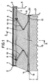
- the awning shown in FIG. 1 has a support device 1 to be attached to a house wall or the like, which is provided with a winding shaft 4 rotatably mounted in bearing plates 2, 3.
- This winding shaft 4 can be driven in a known manner, specifically as shown in FIG. 1 by means of a self-locking gear 5, which in turn can be driven via a crank rod 6 which can be engaged or disengaged.
- a self-locking gear 5 instead of the transmission 5 with crank rod 6, an electromotive drive, a belt drive or the like can of course also be used, as is generally known.
- a support rod 7 is furthermore attached between the bearing plates 2 and 3. On which, by means of clamps 8, 9, drop arms 10, 11 in a so-called scissor design are attached in the usual way.
- extension arms 10, 11 are each divided in the middle and provided with a swivel joint 12 with a vertical axis.
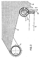
- the failure arms 10, 11 are articulated with the same type of pivot joints 13 on the clamps 8, 9 and - as indicated in FIG. 2 - on a drop tube 14, so that the drop tube 14 can be moved in a plane common with the winding shaft 4, but cannot make any movements perpendicular to this plane.
- a rectangular awning fabric 15 is fastened to the winding shaft 4 and can be wound up or unwound from the winding shaft 4 by the described rotations.
- the awning fabric 15 is also fixed to the drop tube 14 in a manner to be described further below. Since the unit consisting of the support device 1, the drop arms 10, 11 and the drop tube 14 is arranged when mounted on a wall so that the above-mentioned plane spanned by the drop tube 14 and the winding shaft 4 from the winding shaft 4 on slightly If the drop tube 14 falls inclined towards the drop tube 14 at the bottom relative to the horizontal, the drop tube 14, taking the awning fabric 15 with it when it is being unwound from the winding shaft 4, always falls outward with the extension arms 10, 11 extended. Insofar as the awning has been described so far, it is generally known.
- the drop tube f4 is in one embodiment according to the invention - as in the figures. 1 and 2 - provided with a longitudinal slot 16, which is provided on the side facing away from the winding shaft 4, that is to say on the front side of the drop tube 14.
- a deflection shaft 17 is arranged in the interior of the drop tube 14 and is rotatably mounted in two bearings 18, which are each attached to the two ends of the drop tube 14.
- the awning fabric 15 is guided from the winding shaft 4 over the drop tube 14 to its longitudinal slot 16, which in any case extends over the full width of the awning fabric 15.
- the wrap angle ⁇ of the awning fabric 15 on the drop tube 14 is approximately the same or slightly less than 90 °. It will regularly not be less than 60 °.
- the awning fabric 15 is guided through the longitudinal slot 16 into the interior of the drop tube 14 and looped there around the steering shaft 17.
- the wrap angle ⁇ between awning fabric 15 and deflection shaft 17 is in any case greater than 180 °.
- the awning fabric 15 is then again guided out of the longitudinal slot 16 of the drop tube 14 on the deflecting shaft 17 and hangs down as a valance 19 from the drop tube 14.
- the deflection shaft 17 is secured against twisting, the wrap angles ⁇ and ⁇ are sufficient to generate such a large friction between the awning fabric 15 and the corresponding outer surfaces of the drop tube 14 and the deflection shaft 17; that with a winding or unwinding of the awning fabric 15 on or from the winding shaft 4, the vertical length 1 of the valance 19 reltiv to the drop tube 14 does not change. If, on the other hand, the deflection shaft 17 is rotated in one or the other direction, it takes the awning fabric 15 with it, with the extension or shortening of the valance 19 relative to the drop tube 14.
- the surface of the deflection shaft 17 can be designed in such a way that the friction factor becomes as large as possible.
- the rotary drive of the deflection shaft 17 also takes place here by means of a self-locking transmission 20 which is attached to one end of the drop tube 14 and is coupled to the deflection shaft 17 and can be actuated via a crank rod 21 which can be detached or detached. Depending on the direction of rotation of the crank rod 21, this allows the deflection shaft 17 to be rotated in one of the directions of rotation indicated by the double direction of rotation arrow 23.
- a self-locking transmission 20 an electric motor drive or a handwheel drive can of course also be provided.
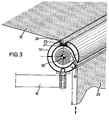
- the awning fabric 15 is fastened to the dropout tube 14 'in a conventional manner.
- the drop tube 14 ' has an undercut piping groove 25 on its upper side, in which the piping is provided on its outer edge hem 26 provided awning 15 is held by means of a piping rod 27 inserted into the piping hem 26 and the piping groove 25.
- This type of attachment of the awning fabric 15 to a drop tube is common.
- the drop pipe 14 ' is again provided on its front side with a longitudinal slot 16'.
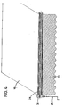
- a valance shaft 28 is mounted in the drop tube 14 'in the same way as in the embodiment according to FIG. 1 at both ends of the drop tube 14'.
- a valance 29 is fastened to this valance shaft 28, the length 1 'of which freely hanging out of the drop tube 14' can be changed by winding or unwinding a part of the valance 29 on or from the valance shaft 28.
- the same devices can be used to drive the valance shaft 28, which have already been described above for the embodiment according to FIGS. 1 and 2.
- a self-locking gear 30 is thus attached to the drop tube 14 ', by means of which the valance shaft 28 can be rotated by means of a crank rod 31 while the valance 29 is wound up or unwound. If there is no actuation via the crank rod 31, the valance shaft 28 is blocked in the respective position.
Description
Die Erfindung betrifft eine Markise, bestehend aus einer drehantreibbaren Wickelwelle für ein Markisentuch, und einem mit der Wickelwelle abstandsveränderbar verbundenen Ausfallrohr, wobei das Markisentuch einerseits an der Wickelwelle befestigt und andererseits an dem Ausfalljohr festgelegt ist und wobei an dem Ausfallrohr ein frei herabhängender Volant vorgesehen ist.The invention relates to an awning, consisting of a rotatably drivable winding shaft for an awning cloth, and a drop tube connected to the winding shaft in a variable distance, the awning cloth being attached to the winding shaft on the one hand and fixed to the drop tube on the other hand and a freely hanging valance being provided on the drop tube .
Derartige Markisen sind z.B. aus der DE - A - 2359132 bekannt und entsprechen der allgemein üblichen Ausführung. In der Regel ist die Wickelwelle an einer Trageinrichtung befestigt, die an einer Hauswand befestigt wird. An dieser Trageinrichtung sind Ausfallarme mit einem Ende angelenkt, an deren anderem Ende das Ausfallrohr angelenkt ist. Diese Ausfallarme sind längenveränderbar. Um bei einem Abwickeln des Markisentuchs von der Wickelwelle ein Ausfallen des Ausfallrohres mit dem Markisentuch zu erreichen, sind die Ausfallarme so angeordnet, daß das Ausfallen des Ausfallrohres in einer gegenüber der Horizontalen leicht nach unten geneigten Ebene erfolgt. Um die Stellung der Markise an unterschiedliche Einfallwinkel des Sonnenlichtes anpassen zu können, ist es bereits aus der DE - A - 2359132 bekannt, die gesamte Markise einschließlich eines Teils der Trageinrichtung der Wickelwelle gegenüber der sie tragenden Wand um eine horizontale Achse schwenkbar auszubilden, so daß die gesamte Markise unterschiedlich stark gegenüber der erwähnten horizontalen Ebene geneigt werden kann. Eine solche Ausbildung setzt eine außerordentlich robuste Trageinrichtung an der Wand voraus. Ein weiterer Nachteil besteht darin, daß bei einem stärkeren Neigen der Markise diese bis unter die Stehhöhe von Benutzem abgesenkt wird.Such awnings are e.g. known from DE-A-2359132 and correspond to the generally customary design. As a rule, the winding shaft is attached to a support device which is attached to a house wall. Failure arms are articulated on this support device at one end, at the other end of which the failure tube is articulated. These extension arms can be changed in length. In order to prevent the extension tube from falling out with the awning fabric when the awning cover is unwound from the winding shaft, the extension arms are arranged in such a way that the extension tube falls out in a plane that is slightly inclined downward from the horizontal. In order to be able to adapt the position of the awning to different angles of incidence of sunlight, it is already known from DE - A - 2359132 to make the entire awning including part of the support device of the winding shaft pivotable about a horizontal axis with respect to the wall carrying it, so that the entire awning can be tilted to different degrees with respect to the horizontal plane mentioned. Such training requires an extremely robust support device on the wall. Another disadvantage is that when the awning tilts more it is lowered to below the standing height of users.
Der Erfindung liegt die Aufgabe zugrunde, eine Markise der eingangs beschriebenen Art so auszubilden, daß mit einfachen Maßnahmen eine Anpassung an unterschiedliche Einfallwinkel des Sonnenlichts möglich ist, ohne daß die gesamte Markise in ihrem Ausfallwinkel verändert zu werden braucht.The invention has for its object to provide an awning of the type described in such a way that adaptation to different angles of incidence of sunlight is possible with simple measures without the entire angle of the awning having to be changed.
Diese Aufgabe wird erfindungsgemäß dadurch gelöst, daß der Volant in seiner freien Länge veränderbar ist. Hierdurch wird erreicht, daß die Markise selbst in ihrem Ausfallwinkel und damit relativ zu dem von ihr geschützten Raum unverändert bleibt. Je nachdem, ob der Einfall des Sonnenlichts flacher oder steiler ist, wird die Länge des Volants verändert, so daß immer ein guter Schutz gegen Sonneneinstrahlung erreicht wird, ohne daß die freie Höhe unter der Markise verändert zu werden braucht. Es ist hierbei naturgemäß auch möglich, den Volant praktisch vollständig verschwinden zu lassen. Darüber hinaus kann der Volant auch zusätzlich als Wind- oder Regenschutz verwendet werden, wenn er auf eine entsprechend große freie Länge gegenüber dem Ausfallrohr ausgefahren wird.This object is achieved in that the valance can be changed in its free length. This ensures that the awning remains unchanged even in its angle of failure and thus relative to the space protected by it. Depending on whether the incidence of sunlight is shallower or steeper, the length of the valance is changed so that good protection against solar radiation is always achieved without the free height under the awning having to be changed. It is naturally also possible to make the valance disappear almost completely. In addition, the valance can also be used as wind or rain protection if it is extended to a correspondingly large free length in relation to the downpipe.
Bei einer besonders vorteilhaften Ausgestaltung der Erfindung sind das Markisentuch und der Volant einstückig ausgebildet und sind das Markisentuch und damit der Volant an unterschiedlichen Stellen relativ zum Ausfall- rohr festlegbar. Bei dieser Ausgestaltung wird das als Markisentuch und als Volant dienende einstückige Tuch lediglich je nach gewünschter Volantlänge an dem Ausfallrohr festgelegt. Die gewünschte Ausfallänge des Ausfallrohres relativ zur Wickelwelle wird dann durch Auf- oder Abwickeln des Markisentuches auf bzw. von der Wickelwelle festgelegt.In a particularly advantageous embodiment of the invention, the awning fabric and the valance are formed in one piece and the awning fabric and thus the valance can be fixed at different points relative to the drop tube. In this embodiment, the one-piece cloth serving as an awning cloth and as a valance is only attached to the drop tube depending on the desired valance length. The desired length of the drop tube relative to the winding shaft is then determined by winding or unwinding the awning fabric on or from the winding shaft.
Als eine besonders elegante Lösung hat sich erwiesen, wenn im Ausfallrohr eine gegen Verdrehungen festlegbare Umlenkwelle angeordnet ist und wenn im Ausfall-rohr ein Längsschlitz vorgesehen ist, durch den das Markisentuch in das Ausfallrohr eingeführt und nach Umschlingung der Umlenkwelle wieder als Volant herausgeführt ist. Hierbei werden also die gesamten Einrichtungen zum Festlegen des Markisentuches und damit des Volants am Ausfallrohr und die Einrichtungen zur Veränderung der Volantlänge unsichtbar in das Ausfallrohr verlegt. Durch die aufgrund der großen Umschlingung bewirkte Reibung wird eine ausreichend feste Festlegung des Markisentuchs und damit des Volants erreicht, wenn die Umlenkwelle gegen Verdrehungen gesichert ist.It has proven to be a particularly elegant solution if a deflection shaft which can be fixed against rotation is arranged in the drop tube and if a longitudinal slot is provided in the drop tube through which the awning fabric is inserted into the drop tube and, after being looped around the deflection shaft, is brought out again as a valance. In this case, the entire devices for fixing the awning fabric and thus the valance on the drop tube and the devices for changing the valance length are moved invisibly into the drop tube. Due to the friction caused by the large wrap, the awning fabric and thus the valance are secured sufficiently firmly when the deflection shaft is secured against twisting.
Eine besonders einfache Längenverstellung des Volants wird erreicht, wenn die Umlenkwelle drehantreibbar ausgebildet ist, was über selbsthemmende Getriebe mit Handkurbelantrieb geschehen kann, wie sie als Antrieb für die Wickelwellen üblich sind. Desgleichen kann auch ein elektromotorischer Antrieb unter Zwischenschaltung eines selbsthemmenden Getriebei. vorgesehen sein, wie es ebenfalls bereits für den Antrieb von Wickelwellen bekannt ist. Es ist aber auch möglich, lediglich eine Verriegelung für die Umlenkwelle vorzusehen, wobei dann Längenverstellungen des Volants in der Weise geschehen, daß nach Lösen dieser Verriegelung der Volant oder das Markisentuch aus dem angehobenen und damit entlasteten Ausfallrohr herausgezogen werden. Eine andere vorteilhafte Ausgestaltung der Erfindung zeichnet sich dadurch aus, daß das Markisentuch am Ausfallrohr befestigt ist und in dem Ausfallrohr eine drehantreibbare Volantwelle angeordnet ist, an der der Volant befestigt ist und daß das Ausfallrohr mit einem Längsschlitz versehen ist, durch den der Volant herausgeführt ist. Bei dieser Ausgestaltung ist also der Volant gleichermaßen wie eine aufwickelbare Jalousie in dem Ausfallrohr untergebracht.A particularly simple length adjustment of the valance is achieved if the deflecting shaft is designed to be rotationally drivable, which can be done via self-locking gears with a hand crank drive, as are customary as drives for the winding shafts. Likewise, an electric motor drive with the interposition of a self-locking transmission. be provided, as is also already known for the drive of winding shafts. But it is also possible to provide only a lock for the deflecting shaft, length adjustments of the valance then taking place in such a way that after releasing this lock, the valance or the awning fabric is pulled out of the raised and thus relieved drop tube. Another advantageous embodiment of the invention is characterized in that the awning fabric is attached to the drop tube and in the drop tube a revolvable valance shaft is arranged to which the valance is attached and that the drop tube is provided with a longitudinal slot through which the valance is led out . In this embodiment, the valance is housed in the drop tube in the same way as a roll-up blind.
Weitere Vorteile und Einzolheiten der Erfindung ergeben sich aus der Beschreibung von zwei Ausführungsbeispielen anhand der Zeichnung. In der Zeichnung zeigt
- Fig. 1 eine Markise gemäß der Erfindung in einer perspektivischen Ansicht schräg von oben,
- Fig. 2 einen Teilschnitt durch Fig. 1 gemäß der Schnittlinie 11-11 in Fig. 1 in perspektivischer Darstellung,
- Fig. 3 eine andere Ausführungsform in einer Fig. 2 entsprechenden Darstellung und
- Fig. 4einen Längsschnitt durch das Ausfallrohr 'nach Fig. 3.
- 1 is an awning according to the invention in a perspective view obliquely from above,
- 2 is a partial section through FIG. 1 along the section line 11-11 in FIG. 1 in a perspective view,
- Fig. 3 shows another embodiment in a representation corresponding to Fig. 2 and
- 4 shows a longitudinal section through the outlet pipe according to FIG. 3.
Die in Fig. 1 dargestellte Markise weist eine an einer Hauswand od. dgl. zu befestigende Trageinrichtung 1 auf, die mit einer in Lagerplatten 2,3 drehbar gelagerten Wickelwelle 4 versehen ist. Diese Wickelwelle 4 ist in bekannter Weise drehantreibbar, und zwar gemäß der Darstellung in Fig. 1 mittels eines selbsthemmenden Getriebes, 5, das wiederum über eine ein- bzw. aushängbare Kurbelstange 6 antreibbar ist. Anstelle des Getriebes 5 mit Kurbelstange 6 kann selbstverständlich auch-wie allgemein bekannt-ein elektromotorischer Antrieb, ein Gurtantrieb od. dgl. verwendet werden. Als Teil der Trageinrichtung 1 ist weiterhin zwischen den Lagerplatten 2 und 3. eine Tragstange 7 angebracht, an der mittels Schellen 8, 9 in üblicher Weise Ausfallarme 10, 11 in sogenannter Scherenausführung angebracht sind. Diese Ausfallarme 10, 11 sind jeweils in ihrer Mitte geteilt und mit einem Schwenkgelenk 12 mit vertikaler Achse versehen. Die Ausfallarme 10, 11 sind mit gleichartigen Schwenkgelenken 13 an den Schellen 8, 9 und-wie in Fig. 2 angedeutet ist- an einem Ausfallrohr 14 angelenkt, so daß das Ausfallrohr 14 in einer mit der Wickelwelle 4 gemeinsamen Ebene verschoben werden kann, aber keine Bewegungen senkrecht zu dieser Ebene ausführen kann.The awning shown in FIG. 1 has a
An der Wickelwelle 4 is ein rechteckiges markisentuch 15 befestigt, das durch die geschilderten Drehungen der Wickelwelle 4 auf diese auf- bzw. von dieser abgewickelt werden kann. Das Markisentuch 15 ist weiterhin in einer weiter unten noch zu schildernden Weise an dem Ausfallrohr 14 festgelegt. Da die aus der Trageinrichtung 1, den Ausfallarmen 10, 11 und dem Ausfallrohr 14 bestehende Einheit bei der Anbringung an einer Wand so angeordnet wird, daß die vorstehend erwähnte, durch das Ausfallrohr 14 und die Wickelwelle 4 aufgespannte Ebene von der Wickelwelle 4 an leicht nach unten gegenüber der Horizontalen geneigt zum Ausfallrohr 14 hin verläuft, fällt das Ausfallrohr 14 unter Mitnahme des Markisentuches 15 bei dessen Abwickeln von der Wickelwelle 4 immer unter Streckung der Ausfallarme 10, 11 nach außen. Insoweit als die Markise bis hierher beschrieben wurde, ist sie allgemein bekannt.A rectangular
Das Ausfallrohr f4 ist bei einer Ausführungsform gemäß der Erfindung-wie in den fig. 1 und 2 dargestellt-mit einem Längsschlitz 16 versehen, der auf der der Wickelwelle 4 abgewandten Seite, also auf der Vorderseite des Ausfallrohres 14 angebracht ist. Im Inneren des Ausfallrohres 14 ist eine Umlenkwelle 17 angeordnet, die in zwei Lagern 18 drehbar gelagert ist, die jeweils an den beiden Enden des Ausfallrohres 14 angebracht sind.The drop tube f4 is in one embodiment according to the invention - as in the figures. 1 and 2 - provided with a
Das Markisentuch 15 ist von der Wickelwelle 4 über das Ausfallrohr 14 bis zu dessen Längsschlitz 16, der sich auf jeden Fall über die volle Breite des Markisentuches 15 erstreckt, geführt. Der Umschlingungswinkel α des Markisentuches 15 auf dem Ausfallrohr 14 ist etwa gleich oder etwas kleiner als 90°. Er wird regelmäßig nicht kleiner als 60° sein. Weiter ist das Markisentuch 15 durch den Längsschlitz 16 in den Innenraum des Ausfallrohres 14 geführt und dort um die Unlenkwelle 17 geschlungen. Der Umschlingungswinkel β zwischen Markisentuch 15 und Umlenkwelle 17 ist auf jeden Fall größer als 180°. An der Umlenkwelle 17 ist das Markisentuch 15 dann wieder aus dem Längsschlitz 16 des Ausfallrohres 14 herausgeführt und hängt als Volant 19 vom Ausfallrohr 14 senk recht herab..The
Wenn die Umlenkwelle 17 gegen ein Verdrehen gesichert ist, reichen die Umschlingungswinkel α und β aus, eine so große Reibung zwischen dem Markisentuch 15 und den entsprechenden mantelflächen des Ausfallrohres 14 und der Umlenkwelle 17 zu erzeugen; daß sich bei einem Auf- oder Abwickeln des Markisentuches 15 auf oder von der Wickelwelle 4 die vertikale Länge 1 des Volants 19 reltiv zum Ausfallrohr 14 nicht ändert. Wird dagegen die Umlenkwelle 17 in der einen oder ,anderen Richtung gedreht, so nimmt sie unter Verlängerung oder Verkürzung des Volants 19 relativ zum Ausfallrohr 14 den Markisenstoff 15 mit. Um eine besonders gute Reibung zwischen der Umlenkwelle 17 und dem Markisentuch 15 zu erreichen, kann die Oberfläche der Umlenkwelle 17 so ausgebildet sein, daß der Reibungsfaktor möglichst groß wird. Hierfür bietet sich eine Gummiummantelung für die-Umlenkwelle 17 oder eine Aufrauhung ihrer Oberfläche an, wenn sie aus Metall besteht.If the
Der Drehantrieb der Umlenkwelle 17 erfolgt auch hier mittels eines an einem Ende des Ausfallrohres 14 angebrachten und mit der Umlenkwelle 17 gekoppelten selbsthemmenden Getriebes 20, das über eine ein- bzw. aushängbare Kurbelstange 21 betätigbar ist. Hierdurch ist je nach Drehrichtung der Kurbelstange 21 eine Verdrehung der Umlenkwelle 17 in eine der durch den Doppel-Drehrichtungspfeil 23 angedeuteten Drehrichtungen möglich. Anstelle eines solchen selbsthemmenden Getriebes 20 kann natürlich auch ein elektromotorischer Antrieb oder ein Handradantrieb vorgesehen sein.The rotary drive of the
Bei einer zweiten Ausführungsform des Ausfallrohes gemäß der Erfindung ist-wie in Fig. 3 dargestellt-der Markisenstoff 15 in üblicher Weise an dem Ausfallrohr 14' befestigt. Hierzu weist das Ausfallrohr 14' an seiner Oberseite eine hinterschnittene Keder-Nut 25 auf, in der der an seinem äußeren Rand mit einem Kedersaum 26 versehene Markisenstöff 15 mittels eines in den Kedersaum 26 und die Keder-Nut 25 eingeschobenen Kederstabes 27 gehalten wird. Diese Art der Befestigung des Markisenstoffes 15 an einem Ausfallrohr ist allgemein üblich. Das Ausfallrohr 14' ist wiederum an seiner Vorderseite mit einem Längsschlitz 16' versehen. In dem Ausfallrohr 14' ist eine Volantwelle 28 in gleicher Weise wie bei der Ausführung nach Fig. 1 an beiden Enden des Ausfallrohres 14' gelagert. An dieser Volantwelle 28 ist ein Volant 29 befestigt, dessen frei aus dem Ausfallrohr 14' heraushängende Länge 1' durch Aufwickeln oder Abwickeln eines Teils des Volants 29 auf bzw. von der Volantwelle 28 verändert werden kann. Zum Antrieb für die Volantwelle 28 können die gleichen Einrichtungen verwendet werden, die vorstehend auch schon für die Ausführungsform nach den Fig. 1 und 2 beschrieben wurden. Am Ausfallrohr 14' ist also ein selbsthemmendes Getriebe 30 angebracht, über das mittels einer Kurbelstange 31 die Volantwelle 28 unter Auf- oder Abwickeln des Volants 29 gedreht werden kann. Erfolgt keine Betätigung über die Kurbelstange 31, so ist die Volantwelle 28 in der jeweiligen Stellung blockiert.In a second embodiment of the dropout tube according to the invention, as shown in FIG. 3, the
Claims (5)
Applications Claiming Priority (2)
| Application Number | Priority Date | Filing Date | Title |
|---|---|---|---|
| DE2746848A DE2746848C2 (en) | 1977-10-19 | 1977-10-19 | awning |
| DE2746848 | 1977-10-19 |
Publications (2)
| Publication Number | Publication Date |
|---|---|
| EP0001592A1 EP0001592A1 (en) | 1979-05-02 |
| EP0001592B1 true EP0001592B1 (en) | 1980-08-20 |
Family
ID=6021728
Family Applications (1)
| Application Number | Title | Priority Date | Filing Date |
|---|---|---|---|
| EP78101063A Expired EP0001592B1 (en) | 1977-10-19 | 1978-10-04 | Retractable awning |
Country Status (6)
| Country | Link |
|---|---|
| US (1) | US4214621A (en) |
| EP (1) | EP0001592B1 (en) |
| AT (1) | AT370179B (en) |
| DE (2) | DE7732200U1 (en) |
| DK (1) | DK148542C (en) |
| IT (1) | IT7823073V0 (en) |
Families Citing this family (50)
| Publication number | Priority date | Publication date | Assignee | Title |
|---|---|---|---|---|
| DE3001919C2 (en) * | 1980-01-19 | 1984-05-17 | Viktor 7032 Sindelfingen Lohausen | awning |
| AT372465B (en) * | 1980-03-21 | 1983-10-10 | Grabher Helmut Fa | AWNING |
| DE3440446A1 (en) * | 1984-11-06 | 1986-05-22 | Bernhard Spettmann, Metallverarbeitung, 2350 Neumünster | Awning |
| US4640332A (en) * | 1985-07-29 | 1987-02-03 | Turner Joe D | Awning support assembly |
| EP0230476B1 (en) * | 1985-10-25 | 1989-03-29 | Carlo Maurizio Pozzi | Safety device against the accidental opening of awnings mounted on vehicles, in particular campers, caravans and similar vehicles |
| DE3744590C1 (en) * | 1987-12-31 | 1989-09-14 | Clauss Markisen | Inclined awning with subsequent vertical area |
| US5273095A (en) * | 1991-03-21 | 1993-12-28 | Lukos Stephen P | Arm structure for awning support system |
| US5119867A (en) * | 1991-03-21 | 1992-06-09 | Lukos Stephen P | Arm structure for awning support system |
| US5280687A (en) * | 1992-12-30 | 1994-01-25 | The Dometic Corporation | Extended awning for slide-outs |
| GB9314151D0 (en) * | 1993-07-08 | 1993-08-18 | Louver Lite Ltd | Blinds |
| DE19524420C2 (en) * | 1995-07-05 | 1998-10-22 | Mhz Sonnenschutztech Gmbh | Awning with retractable valance |
| DE29516329U1 (en) * | 1995-10-14 | 1995-12-07 | Wis Mar Wieslocher Markisen Un | awning |
| IT242278Y1 (en) * | 1996-05-28 | 2001-06-04 | Umberto Longoni | AWNING WITH SPRING ARMS AND CONTAINER WITH DISAPPEARANCE TOTAL OF ARMS AND COVERS |
| DE29612532U1 (en) * | 1996-07-19 | 1996-10-02 | Schmitz Werke | Articulated arm for an articulated arm awning |
| US5860440A (en) * | 1996-11-26 | 1999-01-19 | Carefree/Scott Fetzer Company | Retractable awning for recreational vehicle or the like |
| DE19741111A1 (en) * | 1997-09-18 | 1999-03-25 | Schmitz Werke | Articulated arm for an articulated arm awning and method for its production |
| DE19823199A1 (en) * | 1998-05-23 | 1999-11-25 | Schmitz Werke | awning |
| US6494246B1 (en) * | 1998-08-03 | 2002-12-17 | Timothy D. Blevins | Retractable awning and method |
| DE19949215A1 (en) * | 1999-10-13 | 2001-04-19 | Schmitz Werke | awning |
| DE10001757C2 (en) * | 2000-01-18 | 2002-04-18 | Schmitz Werke | vertical awning |
| US6484069B2 (en) * | 2000-01-31 | 2002-11-19 | Turnils Ab | Awning assembly and control system |
| CA2323843A1 (en) | 2000-10-19 | 2002-04-19 | Emilio Petrongolo | Awning opening and closing device |
| US6957679B2 (en) * | 2003-03-26 | 2005-10-25 | Powell & Powell Supply Co., Inc. | Retractable awning |
| KR100551943B1 (en) * | 2003-11-12 | 2006-02-20 | 이종석 | awning |
| US20050103371A1 (en) * | 2003-11-17 | 2005-05-19 | Gary D. Childres | Retractable terrace canopy |
| US20050183236A1 (en) * | 2004-01-15 | 2005-08-25 | Wichman Donald P. | Sliding replacement door |
| DE202004000975U1 (en) * | 2004-01-22 | 2004-04-01 | Dr. Krüger KG | awning |
| US7513289B2 (en) * | 2004-06-07 | 2009-04-07 | Girard Systems | Slide-lateral arm box awning for motor home and recreational vehicle use |
| US7261115B2 (en) * | 2004-06-07 | 2007-08-28 | Girard Systems | Combo slide-window awning |
| WO2006024105A1 (en) * | 2004-09-03 | 2006-03-09 | Gale Pacific Limited | A retractable awning |
| DE202005008724U1 (en) * | 2005-06-03 | 2005-08-04 | Schmitz-Werke Gmbh + Co. Kg | Sun awning has outer end of the cloth anchored to a rod within a box profile with a cover for winding fabric |
| BRPI0520674A2 (en) * | 2005-10-11 | 2009-09-29 | Osamu Ito | movable roofing device and outer corner roller unwind rollers |
| US7740044B2 (en) * | 2006-08-31 | 2010-06-22 | Dometic, LLC | Awning assembly including drop-down shade |
| US20090013614A1 (en) * | 2007-07-13 | 2009-01-15 | Kim Rogers | Retractable rigid roof system |
| WO2012004796A2 (en) | 2010-07-08 | 2012-01-12 | Nadav Gavish | A sheltering device |
| JP2012053378A (en) * | 2010-09-03 | 2012-03-15 | Seiko Epson Corp | Screen device |
| DE102011119726B4 (en) * | 2011-11-30 | 2023-02-02 | Weinor Gmbh & Co. Kg | Cassette awning with concealed mounting brackets |
| EP2628886A1 (en) * | 2012-02-16 | 2013-08-21 | Arvomarkiisi Oy | Profile for a bottom rail of a roller blind |
| US9945177B2 (en) * | 2013-03-15 | 2018-04-17 | Hunter Douglas Inc. | Covering for an architectural opening having nested rollers |
| US9567802B2 (en) * | 2013-03-15 | 2017-02-14 | Hunter Douglas Inc. | Covering for an architectural opening having nested rollers |
| USD735889S1 (en) | 2013-06-14 | 2015-08-04 | Schmitz-Werke Gmbh + Co. Kg | Awning holder |
| US9469997B2 (en) | 2013-12-12 | 2016-10-18 | Carefree/Scott Fetzer Company | Lateral arm awning system and method of operation |
| CN105083143A (en) | 2014-09-18 | 2015-11-25 | 宁波万汇窗篷用品有限公司 | Awning device |
| US10947736B2 (en) | 2016-03-25 | 2021-03-16 | Carefree/Scott Fetzer Company | Residential awning canopy assembly |
| US20170275884A1 (en) | 2016-03-25 | 2017-09-28 | Carefree/Scott Fetzer Company | Residential awning canopy assembly |
| US10428549B2 (en) | 2016-04-01 | 2019-10-01 | ZHUN-AN Ma | Awning apparatus |
| CN108166688B (en) * | 2017-05-08 | 2019-11-05 | 宁波万汇休闲用品有限公司 | Cover paulin device |
| EP3495582A1 (en) | 2017-12-08 | 2019-06-12 | Activa Awning Inc. | Awning apparatus |
| EP3741924B1 (en) * | 2019-05-24 | 2022-10-12 | weinor GmbH & Co. KG | Conservatory awning with valance |
| US11821212B2 (en) * | 2019-09-18 | 2023-11-21 | Carefree/Scott Fetzer Company | Drop canopy with screen |
Family Cites Families (9)
| Publication number | Priority date | Publication date | Assignee | Title |
|---|---|---|---|---|
| US1326801A (en) * | 1919-12-30 | Awning-edge-holding device | ||
| US618906A (en) * | 1899-02-07 | Awning-operating device | ||
| US800111A (en) * | 1903-03-16 | 1905-09-19 | Willard C James | Partition device for rooms. |
| US1562355A (en) * | 1925-01-02 | 1925-11-17 | Manassa Jerome | Awning |
| FR2056019A5 (en) * | 1969-08-14 | 1971-05-14 | Herscovici Etienne | |
| DE1951672A1 (en) * | 1969-10-14 | 1971-04-29 | Schneider Co Optische Werke | Circuit arrangement for optical devices |
| DE2359132A1 (en) * | 1973-11-28 | 1975-06-12 | Adolf Merkel Ohg | Hinged-bracket-mounted awning roller - with ends rotating on angleplate arms with swivelling plates for brackets |
| US3923074A (en) * | 1974-11-11 | 1975-12-02 | Scott & Fetzer Co | Enclosable retractable awning |
| US4077419A (en) * | 1975-06-16 | 1978-03-07 | Phil Lux | Awning apparatus for travel trailers, mobile homes, and the like |
-
1977
- 1977-10-19 DE DE7732200U patent/DE7732200U1/en not_active Expired
- 1977-10-19 DE DE2746848A patent/DE2746848C2/en not_active Expired
-
1978
- 1978-09-12 US US05/941,846 patent/US4214621A/en not_active Expired - Lifetime
- 1978-09-26 DK DK425978A patent/DK148542C/en not_active IP Right Cessation
- 1978-10-04 EP EP78101063A patent/EP0001592B1/en not_active Expired
- 1978-10-17 IT IT7823073U patent/IT7823073V0/en unknown
- 1978-10-18 AT AT0747978A patent/AT370179B/en active
Also Published As
| Publication number | Publication date |
|---|---|
| EP0001592A1 (en) | 1979-05-02 |
| DK148542C (en) | 1986-01-06 |
| IT7823073V0 (en) | 1978-10-17 |
| DE2746848A1 (en) | 1979-05-03 |
| US4214621A (en) | 1980-07-29 |
| DE7732200U1 (en) | 1978-02-09 |
| DE2746848C2 (en) | 1983-10-13 |
| DK148542B (en) | 1985-07-29 |
| AT370179B (en) | 1983-03-10 |
| DK425978A (en) | 1979-04-20 |
| ATA747978A (en) | 1982-07-15 |
Similar Documents
| Publication | Publication Date | Title |
|---|---|---|
| EP0001592B1 (en) | Retractable awning | |
| DE2312661C3 (en) | Pleated blind | |
| DE4006485A1 (en) | Sun blind arrangement - uses two motor-driven winding shafts operating in opposite rotary tractive directions | |
| EP0335177B1 (en) | Arrangement for darkening windows | |
| AT502509B1 (en) | LOUVRE | |
| EP0872611A2 (en) | Awning, especially an awning with articulated arms | |
| AT394420B (en) | OPERATING DEVICE FOR A ROLLER SHUTTER FOR A ROOF WINDOW | |
| AT1391U1 (en) | COVER FOR THE DARKENING OF WINDOW OPENINGS | |
| DE4401056C1 (en) | Roller blind for a roof window | |
| EP0079434B1 (en) | Venetian blind | |
| CH682095A5 (en) | Sun protection with several lamellas synchronously pivotable around parallel axes - involves each lamella with surface of solar cells facing the same direction and pivotable up to 180 deg. | |
| CH650305A5 (en) | AWNING. | |
| DE102010017729A1 (en) | Vertical blind and sun guard for awning in e.g. balcony, of building, has connecting unit connecting support rail with arm of awning, where connecting unit defines adjustable spacing between arm of awning and support rail | |
| DE19808624C1 (en) | Electrically operated roller blind for providing sun, heat and sound protection for window | |
| DE1928212U (en) | ROLLER SHUTTERS WITH EXTENDABLE SLATS. | |
| DE2835959C3 (en) | Insect protection device for windows, doors or the like. | |
| DE2535492C3 (en) | Natural draft cooling tower | |
| DE19949163C1 (en) | Sun blind awning for a building facade has vertical guide rails for sliding rails with sliding shoes and a lateral awning guide tube to give an effective shade and a view from the window unaffected by wind | |
| EP3228801B1 (en) | Vertical shading with adjustable mounting brackets | |
| DE3440446C2 (en) | ||
| DE19923724B4 (en) | louvre | |
| DE4304923A1 (en) | Roller-blind element and building equipped therewith | |
| DE3420452C2 (en) | Slatted venetian blind, especially for glass roofs | |
| DE2527860C3 (en) | Partial awning | |
| DE1509395C (en) | Sun protection device in front of building windows |
Legal Events
| Date | Code | Title | Description |
|---|---|---|---|
| PUAI | Public reference made under article 153(3) epc to a published international application that has entered the european phase |
Free format text: ORIGINAL CODE: 0009012 |
|
| 17P | Request for examination filed | ||
| AK | Designated contracting states |
Designated state(s): BE CH FR GB NL SE |
|
| GRAA | (expected) grant |
Free format text: ORIGINAL CODE: 0009210 |
|
| AK | Designated contracting states |
Designated state(s): BE CH FR GB NL SE |
|
| PG25 | Lapsed in a contracting state [announced via postgrant information from national office to epo] |
Ref country code: NL Effective date: 19801130 |
|
| NLV1 | Nl: lapsed or annulled due to failure to fulfill the requirements of art. 29p and 29m of the patents act | ||
| PGFP | Annual fee paid to national office [announced via postgrant information from national office to epo] |
Ref country code: GB Payment date: 19930927 Year of fee payment: 16 |
|
| PGFP | Annual fee paid to national office [announced via postgrant information from national office to epo] |
Ref country code: SE Payment date: 19931022 Year of fee payment: 16 |
|
| PGFP | Annual fee paid to national office [announced via postgrant information from national office to epo] |
Ref country code: BE Payment date: 19931105 Year of fee payment: 16 |
|
| PGFP | Annual fee paid to national office [announced via postgrant information from national office to epo] |
Ref country code: CH Payment date: 19940905 Year of fee payment: 17 |
|
| PG25 | Lapsed in a contracting state [announced via postgrant information from national office to epo] |
Ref country code: GB Effective date: 19941004 |
|
| PG25 | Lapsed in a contracting state [announced via postgrant information from national office to epo] |
Ref country code: SE Effective date: 19941005 |
|
| PGFP | Annual fee paid to national office [announced via postgrant information from national office to epo] |
Ref country code: FR Payment date: 19941017 Year of fee payment: 17 |
|
| PG25 | Lapsed in a contracting state [announced via postgrant information from national office to epo] |
Ref country code: BE Effective date: 19941031 |
|
| EAL | Se: european patent in force in sweden |
Ref document number: 78101063.2 |
|
| BERE | Be: lapsed |
Owner name: SCHMITZ-WERKE G.M.B.H. & CO. Effective date: 19941031 |
|
| GBPC | Gb: european patent ceased through non-payment of renewal fee |
Effective date: 19941004 |
|
| EUG | Se: european patent has lapsed |
Ref document number: 78101063.2 |
|
| PG25 | Lapsed in a contracting state [announced via postgrant information from national office to epo] |
Ref country code: CH Effective date: 19951031 |
|
| REG | Reference to a national code |
Ref country code: CH Ref legal event code: PL |
|
| PG25 | Lapsed in a contracting state [announced via postgrant information from national office to epo] |
Ref country code: FR Effective date: 19960628 |
|
| REG | Reference to a national code |
Ref country code: FR Ref legal event code: ST |
|
| PLBE | No opposition filed within time limit |
Free format text: ORIGINAL CODE: 0009261 |
|
| STAA | Information on the status of an ep patent application or granted ep patent |
Free format text: STATUS: NO OPPOSITION FILED WITHIN TIME LIMIT |