DE202008009894U1 - Electrical connector - Google Patents

Electrical connector Download PDF

Info

Publication number
DE202008009894U1
DE202008009894U1 DE202008009894U DE202008009894U DE202008009894U1 DE 202008009894 U1 DE202008009894 U1 DE 202008009894U1 DE 202008009894 U DE202008009894 U DE 202008009894U DE 202008009894 U DE202008009894 U DE 202008009894U DE 202008009894 U1 DE202008009894 U1 DE 202008009894U1
Authority
DE
Germany
Prior art keywords
inner part
plastic inner
electrical connector
holes
connection holes
Prior art date
Legal status (The legal status is an assumption and is not a legal conclusion. Google has not performed a legal analysis and makes no representation as to the accuracy of the status listed.)
Expired - Lifetime
Application number
DE202008009894U
Other languages
German (de)
Current Assignee (The listed assignees may be inaccurate. Google has not performed a legal analysis and makes no representation or warranty as to the accuracy of the list.)
Jess Link Products Co Ltd
Original Assignee
Jess Link Products Co Ltd
Priority date (The priority date is an assumption and is not a legal conclusion. Google has not performed a legal analysis and makes no representation as to the accuracy of the date listed.)
Filing date
Publication date
Application filed by Jess Link Products Co Ltd filed Critical Jess Link Products Co Ltd
Priority to DE202008009894U priority Critical patent/DE202008009894U1/en
Publication of DE202008009894U1 publication Critical patent/DE202008009894U1/en
Anticipated expiration legal-status Critical
Expired - Lifetime legal-status Critical Current

Links

Classifications

    • HELECTRICITY
    • H01ELECTRIC ELEMENTS
    • H01RELECTRICALLY-CONDUCTIVE CONNECTIONS; STRUCTURAL ASSOCIATIONS OF A PLURALITY OF MUTUALLY-INSULATED ELECTRICAL CONNECTING ELEMENTS; COUPLING DEVICES; CURRENT COLLECTORS
    • H01R13/00Details of coupling devices of the kinds covered by groups H01R12/70 or H01R24/00 - H01R33/00
    • H01R13/46Bases; Cases
    • H01R13/502Bases; Cases composed of different pieces
    • H01R13/506Bases; Cases composed of different pieces assembled by snap action of the parts
    • HELECTRICITY
    • H01ELECTRIC ELEMENTS
    • H01RELECTRICALLY-CONDUCTIVE CONNECTIONS; STRUCTURAL ASSOCIATIONS OF A PLURALITY OF MUTUALLY-INSULATED ELECTRICAL CONNECTING ELEMENTS; COUPLING DEVICES; CURRENT COLLECTORS
    • H01R13/00Details of coupling devices of the kinds covered by groups H01R12/70 or H01R24/00 - H01R33/00
    • H01R13/648Protective earth or shield arrangements on coupling devices, e.g. anti-static shielding  
    • H01R13/658High frequency shielding arrangements, e.g. against EMI [Electro-Magnetic Interference] or EMP [Electro-Magnetic Pulse]
    • H01R13/6581Shield structure
    • H01R13/6585Shielding material individually surrounding or interposed between mutually spaced contacts
    • HELECTRICITY
    • H01ELECTRIC ELEMENTS
    • H01RELECTRICALLY-CONDUCTIVE CONNECTIONS; STRUCTURAL ASSOCIATIONS OF A PLURALITY OF MUTUALLY-INSULATED ELECTRICAL CONNECTING ELEMENTS; COUPLING DEVICES; CURRENT COLLECTORS
    • H01R13/00Details of coupling devices of the kinds covered by groups H01R12/70 or H01R24/00 - H01R33/00
    • H01R13/648Protective earth or shield arrangements on coupling devices, e.g. anti-static shielding  
    • H01R13/658High frequency shielding arrangements, e.g. against EMI [Electro-Magnetic Interference] or EMP [Electro-Magnetic Pulse]
    • H01R13/6591Specific features or arrangements of connection of shield to conductive members
    • H01R13/6592Specific features or arrangements of connection of shield to conductive members the conductive member being a shielded cable
    • HELECTRICITY
    • H01ELECTRIC ELEMENTS
    • H01RELECTRICALLY-CONDUCTIVE CONNECTIONS; STRUCTURAL ASSOCIATIONS OF A PLURALITY OF MUTUALLY-INSULATED ELECTRICAL CONNECTING ELEMENTS; COUPLING DEVICES; CURRENT COLLECTORS
    • H01R2107/00Four or more poles
    • HELECTRICITY
    • H01ELECTRIC ELEMENTS
    • H01RELECTRICALLY-CONDUCTIVE CONNECTIONS; STRUCTURAL ASSOCIATIONS OF A PLURALITY OF MUTUALLY-INSULATED ELECTRICAL CONNECTING ELEMENTS; COUPLING DEVICES; CURRENT COLLECTORS
    • H01R24/00Two-part coupling devices, or either of their cooperating parts, characterised by their overall structure
    • H01R24/60Contacts spaced along planar side wall transverse to longitudinal axis of engagement

Landscapes

  • Details Of Connecting Devices For Male And Female Coupling (AREA)

Abstract

Elektrischer Verbinder, bestehend aus
– einem Kunststoff-Innenteil (10), das mit einer Vielzahl von Anschlusslöchern (11) und einer Vielzahl von Löchern (12) versehen ist, wobei die Anschlusslöcher (11) durch die vordere und die hintere Seite des Kunststoff-Innenteils (10) verlaufen, und die Löcher (12) an der oberen und der unteren Seite des Kunststoff-Innenteils (10) angeordnet sind und jeweils mit den Anschlusslöchern (11) kommunizieren; und
– einer Vielzahl von leitfähigen Anschlüssen (20), die in den Anschlusslöchern (11) des Kunststoff-Innenteils (10) eingesteckt sind.
Electrical connector consisting of
- A plastic inner part (10) which is provided with a plurality of terminal holes (11) and a plurality of holes (12), wherein the connection holes (11) through the front and the rear side of the plastic inner part (10) and the holes (12) are disposed on the upper and lower sides of the plastic inner member (10) and communicate with the terminal holes (11), respectively; and
- A plurality of conductive terminals (20) which are inserted in the connection holes (11) of the plastic inner part (10).

Figure 00000001
Figure 00000001

Description

Die vorliegende Erfindung betrifft einen elektrischen Verbinder, insbesondere einen elektrischen Verbinder, bei dem das Kunststoff-Innenteil mit Löchern versehen ist.The The present invention relates to an electrical connector, in particular an electrical connector, wherein the plastic inner part with Holes is provided.

Durch die Popularität von elektronischen Geräten aller Typen nimmt der Bedarf an Verbindungselementen zwischen elektronischen Geräten, also elektrischen Verbindern, ständig zu. Jedoch stellt sich für die betreffende Industrie die Aufgabe, einen elektrischen Verbinder zu schaffen, der gute elektrische Eigenschaften besitzt und bei dem Signale bei Hochfrequenzübertragung (high frequency transmission) sich nicht leicht abschwächen.By the popularity of electronic devices of all Types decreases the need for fasteners between electronic Devices, ie electrical connectors, constantly to. However, for the industry in question, the Task to create an electrical connector, the good electrical Has properties and the signals in high-frequency transmission (high frequency transmission) does not weaken easily.

Aus dem US-amerikanischen Patent US 6,997,733 ist ein Steckverbinder (plug connector) bekannt, der aus einem Kunststoff-Innenteil und einer Vielzahl von leitfähigen Anschlüssen ausgebildet ist, wobei die leitfähigen Anschlüsse in die Anschlusslöcher des Kunststoff-Innenteils eingesteckt werden, und das Hinterende jedes leitfähigen Anschlusses mit einer Ader eines Kabels verbunden ist. Der Steckverbinder kann mit einem Steckverbinder (socket connector) elektrisch verbunden werden, wodurch das elektrische Signal im Kabel über den Steckverbinder (plug connector) zu einem weiteren an den Steckverbinder (plug connector) angeschlossenes Elektrogerät übertragen werden kann.From the US patent US 6,997,733 For example, a plug connector is known, which is formed of a plastic inner part and a plurality of conductive terminals, wherein the conductive terminals are inserted into the connection holes of the plastic inner part, and the rear end of each conductive terminal connected to a wire of a cable is. The connector can be electrically connected to a socket connector, whereby the electrical signal in the cable can be transmitted via the plug connector to another electrical device connected to the plug connector.

Jedoch weist der herkömmliche Steckverbinder (plug connector) folgende Nachteile auf: im Vergleich zur Impedanz der leitfähigen Anschlüsse ist die Impedanz des Kabels viel höher, so das ihre Impedanzen nicht aufeinander abgestimmt sind, was zu erheblicher Abschwächung des Signals und somit zum Verzug des Signals führen kann, bis das Signal des Kabels zu leitfähigen Anschlüssen übertragen worden ist. Unter Anwendung des elektrischen Verbinders für Hochfrequenz-Übertragung wird die Abschwächung des Signals, also die Folge der Unstimmigkeit der Impedanzen, noch deutlicher.however has the conventional connector (plug connector) the following disadvantages: compared to the impedance of the conductive Connections, the impedance of the cable is much higher, so that their impedances are not matched, resulting in significant Attenuation of the signal and thus to the delay of the signal can lead to the signal of the cable too conductive Connections has been transferred. Under application the electrical connector for high-frequency transmission becomes the attenuation of the signal, that is, the consequence of the discrepancy the impedances, more clearly.

Angesichts dessen hat der Erfinder sich mit dem Studium dieser Technik beschäftigt und sich an diesbezügliche Theorien angelehnt und letztendlich die vorliegende Erfindung hervorgebracht.in view of of which the inventor has dealt with the study of this technique and based on related theories and ultimately the present invention.

Der Erfindung liegt die Aufgabe zugrunde, einen elektrischen Verbinder zu schaffen, bei dem das Kunststoff-Innenteil mit Löchern versehen ist, um die Kontaktfläche der leitfähigen Anschlüsse und der Luft zu vergrößern und somit die Impedanz der leitfähigen Anschlüsse zu erhöhen, so dass die Impedanzen der leitfähigen Anschlüsse und des Kabels miteinander übereinstimmen können.Of the Invention is based on the object, an electrical connector to create, where the plastic inner part with holes is provided to the contact surface of the conductive Connections and the air to enlarge and thus the impedance of the conductive connections increase, so that the impedances of the conductive Connections and the cable match each other can.

Der erfindungsgemäße elektrische Verbinder besteht aus einem Kunststoff-Innenteil, das mit einer Vielzahl von Anschlusslöchern und einer Vielzahl von Löchern versehen ist, wobei die Anschlusslöcher durch die vordere und die hintere Seite des Kunststoff-Innenteils verlaufen und jeweils mit den Anschlusslöchern kommunizieren; und einer Vielzahl von leitfähigen Anschlüssen, die in die Anschlusslöcher des Kunststoff-Innenteils eingesteckt sind.Of the electrical connector according to the invention consists made of a plastic inner part, which has a variety of connection holes and a plurality of holes, wherein the Terminal holes through the front and rear sides of the plastic inner part and in each case with the connection holes communicate; and a plurality of conductive terminals, which are inserted into the connection holes of the plastic inner part are.

Die vorliegende Erfindung weist folgende Vorteile auf: wenn die leitfähigen Anschlüsse im Kunststoff-Innenteil eingesteckt bleiben, ermöglichen die Löcher des Kunststoff-Innenteils eine Vergrößernung der Kontaktfläche der leitfähigen Anschlüsse und der Luft, was zur wirksamen Senkung der Kapazität der leitfähigen Anschlüsse und somit zur Steigerung der Impedanz der leitfähigen Anschlüsse beiträgt.The The present invention has the following advantages: when the conductive Connections remain plugged in the plastic inner part, allow the holes of the plastic inner part an enlargement of the contact surface the conductive connections and the air, causing the effectively reducing the capacity of the conductive Connections and thus increase the impedance of the conductive Connections contributes.

Im Folgenden werden die eingesetzten technischen Inhalte, Maßnahmen und Funktionen der vorliegenden Erfindung anhand der detaillierten Beschreibung und der beigefügten Zeichnungen näher erläutert werden. Jedoch ist die Erfindung nicht auf die Beschreibung und die beigefügten Zeichnungen beschränkt. Es zeigen:in the Following are the used technical contents, measures and functions of the present invention with reference to the detailed Description and the accompanying drawings explained in more detail become. However, the invention is not limited to the description and limited the accompanying drawings. Show it:
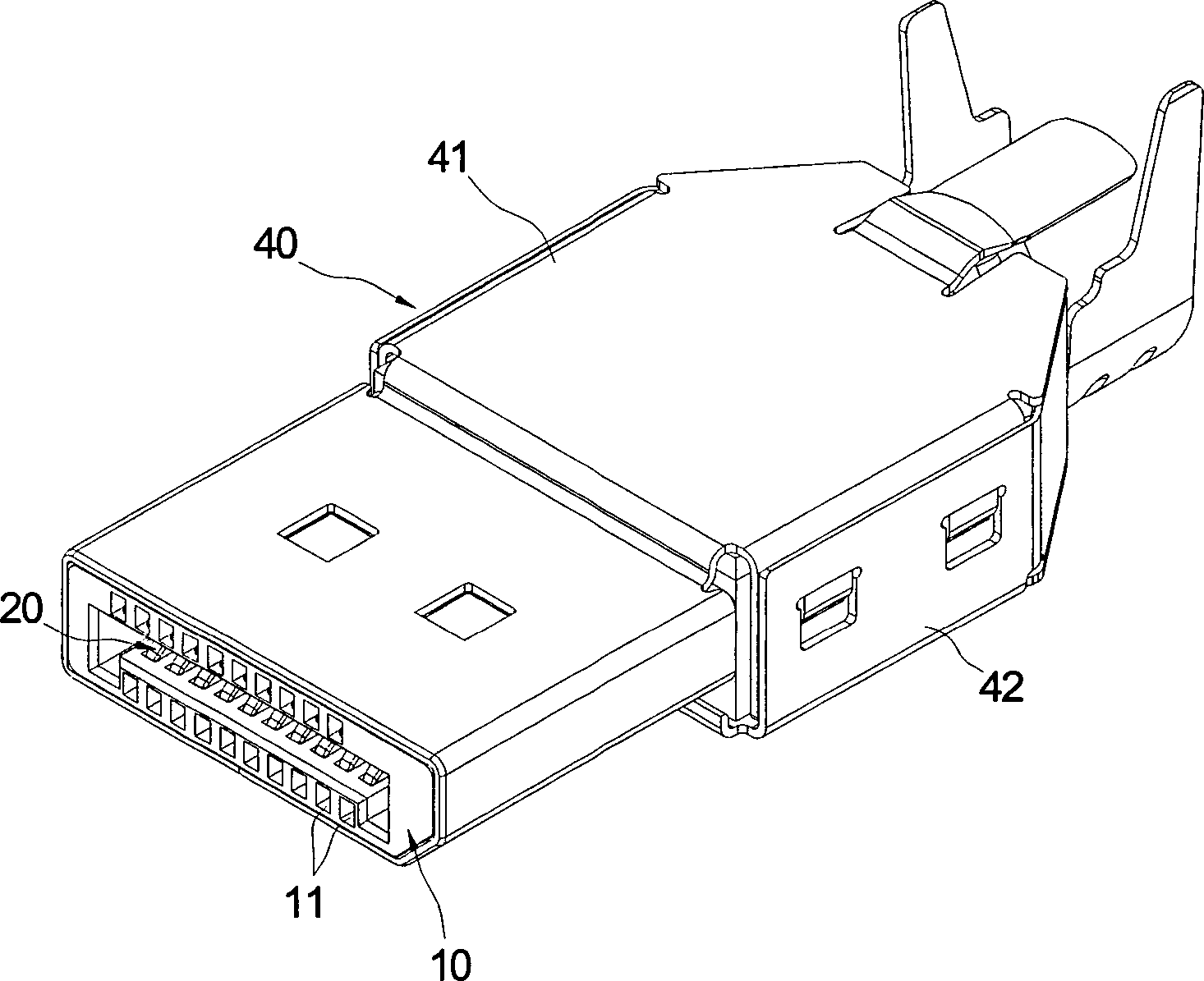
1 eine perspektivische Ansicht eines erfindungsgemäßen elektrischen Verbinders; 1 a perspective view of an electrical connector according to the invention;

2 eine perspektivische Ansicht eines erfindungsgemäßen elektrischen Verbinders im zerlegten Zustand; 2 a perspective view of an electrical connector according to the invention in the disassembled state;

3 eine schematische Darstellung der Löcher des erfindungsgemäßen elektrischen Verbinders; 3 a schematic representation of the holes of the electrical connector according to the invention;

4 eine weitere schematische Darstellung der Löcher des erfindungsgemäßen elektrischen Verbinders; und 4 a further schematic representation of the holes of the electrical connector according to the invention; and

5 eine schematische Darstellung der Löcher des erfindungsgemäßen elektrischen Verbinders gemäß einem zweiten Ausführungsbeispiel. 5 a schematic representation of the holes of the electrical connector according to the invention according to a second embodiment.

Wie aus 1 bis 2 ersichtlich, besteht der erfindungsgemäße elektrische Verbinder aus einem Kunststoff-Innenteil 10, einer Vielzahl von Anschlusslöchern 20, einem hinteren Steckteil 30 und einem Eisengehäuse 40. Der elektrische Verbinder wird im Wesentlichen als elektrischer Verbinder für einen Display-Port angewendet.How out 1 to 2 it can be seen, the electrical connector according to the invention consists of a plastic inner part 10 , a variety of connection holes 20 , a rear plug-in part 30 and an iron housing 40 , The electrical connector is essentially used as an electrical connector for a display port.

Wie aus 3, 4 ersichtlich, ist das Kunststoff-Innenteil 10 aus Isolierstoff hergestellt und weist eine Vielzahl von Anschlusslöchern 11 und eine Vielzahl von Löchern 12 auf. Die Anschlusslöcher 11 sind horizontal in Reihen angeordnet und verlaufen durch die vordere und die hintere Seite des Kunststoff-Innenteils 10 hindurch. Die Löcher 12 sind an der oberen und der unteren Seite des Kunststoff-Innenteils 10 angeordnet und kommunizieren mit den Anschlusslöchern 11. Alternativ können die Löcher 12 nur an der oberen oder unteren Seite des Kunststoff-Innenteils 10 angeordnet werden (nicht dargestellt).How out 3 . 4 can be seen, is the plastic inner part 10 made of insulating material and has a variety of connection holes 11 and a lot of holes 12 on. The connection holes 11 are arranged horizontally in rows and run through the front and the back of the art material inner part 10 therethrough. The holes 12 are on the upper and lower sides of the plastic inner part 10 arranged and communicate with the connection holes 11 , Alternatively, the holes can 12 only on the upper or lower side of the plastic inner part 10 be arranged (not shown).

Die leitfähigen Anschlüsse 20 sind aus Metall mit hohem Leitvermögen hergestellt und werden der Reihe nach in die Anschlusslöcher 11 des Kunststoff-Innenteils 10 eingesteckt. Die Hinterseite der leitfähigen Anschlüsse 20 ragt aus der Hinterseite des Kunststoff-Innenteils 10 heraus.The conductive connections 20 are made of metal with high conductivity and are inserted into the connection holes in turn 11 of the plastic inner part 10 plugged in. The back of the conductive connections 20 protrudes from the back of the plastic inner part 10 out.

Das hintere Steckteil 30 ist ebenfalls aus Isolierstoff hergestellt und steht mit dem Hinterende des Kunststoff-Innenteils 10 in Rastverbindung. Das hintere Steckteil 30 weist ein Zungenteil 31, eine Vielzahl von Durchgangslöchern 32 und eine Vielzahl von Anschlussrinnen 33 auf. Das Zungenteil 31 erstreckt sich von der Hinterseite des hinteren Steckteils 30 nach hinten; die Durchgangslöcher 32 sind horizontal in Reihen angeordnet und verlaufen durch die vordere und die hintere Seite des hinteren Steckteils 30 hindurch, wobei die horizontale Reihung der Durchgangslöcher 32 mit der Position der Anschlusslöcher 11 des Kunststoff-Innenteils 10 korrespondiert. Die Anschlussrinnen 33 sind auf dem Zungenteil 31 angeordnet und kommunizieren mit den Durchgangslöchern 32.The rear plug-in part 30 is also made of insulating material and stands with the rear end of the plastic inner part 10 in locking connection. The rear plug-in part 30 has a tongue part 31 , a variety of through holes 32 and a variety of connection troughs 33 on. The tongue part 31 extends from the rear of the rear male part 30 to the rear; the through holes 32 are arranged horizontally in rows and extend through the front and the rear side of the rear male part 30 through, the horizontal row of through holes 32 with the position of the connection holes 11 of the plastic inner part 10 corresponds. The connection troughs 33 are on the tongue part 31 arranged and communicate with the through holes 32 ,

Wenn das hintere Steckteil 30 mit dem Hinterende des Kunststoff-Innenteils 10 in Verrastung steht, verläuft das Hinterende der leitfähigen Anschlüsse 20 durch die Durchgangslöcher 32 des hinteren Steckteils 30, erstreckt sich in die Anschlussrinnen 33 des Zungenteils 31 und wird dort aufgenommen.If the rear plug-in part 30 with the rear end of the plastic inner part 10 latched, the rear end of the conductive terminals runs 20 through the through holes 32 the rear male part 30 , extends into the connection channels 33 of the tongue part 31 and will be included there.

Nachdem das Kunststoff-Innenteil 10, die leitfähigen Anschlüsse 20 und das hintere Steckteil 30 miteinander zusammengebaut worden sind, wird die Kontaktfläche der leitfähigen Anschlüsse 20 und der Luft deswegen vergrößert, weil die leitfähigen Anschlüsse 20 jeweils mit den Löchern 12 des Kunststoff-Innenteils 10 korrespondieren. Die Dielektrizitätskonstante der Luft ist viel niedriger als die des Kunststoff-Innenteils 10. Wenn beispielsweise das Kunststoff-Innenteil 10 aus Kunststoff ist, liegt seine Dielektrizitätskonstante zwischen 2,4 und 4, während die Dielektrizitätskonstante der Luft 1,0054 beträgt. Da die Dielektrizitätskonstante des Stoffs im proportionalen Verhältnis zur Kapazität steht, sinkt die Kapazität der leitfähigen Anschlüsse 20 mit der Vergrößerung der Kontaktfläche der Luft. Ferner steht die Impedanz des Stoffs im umgekehrten Verhältnis zur Kapazität, so dass die Impedanz desto höher wird, je niedriger die Kapazität ist. Demzufolge steigt die Impedanz der leitfähigen Anschlüsse 20 aufgrund der Senkung der Kapazität.After the plastic inner part 10 , the conductive connections 20 and the rear plug-in part 30 have been assembled together, the contact surface of the conductive terminals 20 and the air is enlarged because of the conductive connections 20 each with the holes 12 of the plastic inner part 10 correspond. The dielectric constant of the air is much lower than that of the plastic inner part 10 , If, for example, the plastic inner part 10 is made of plastic, its dielectric constant is between 2.4 and 4, while the dielectric constant of the air is 1.0054. Since the dielectric constant of the substance is proportional to the capacitance, the capacitance of the conductive terminals decreases 20 with the increase of the contact surface of the air. Further, the impedance of the substance is in inverse proportion to the capacity, so that the lower the capacity, the higher the impedance becomes. As a result, the impedance of the conductive terminals increases 20 due to the reduction in capacity.

Wenn später das hintere Ende der leitfähigen Anschlüsse 20 mit einem Kabel (nicht dargestellt) mit einer höheren Impedanz verbunden ist, dann wird kein großer Unterschied zwischen den Impedanzen der leitfähigen Anschlüsse 20 und des Kabels bestehen, so dasss keine Unabstimmigkeit der Impedanzen vorliegt. Damit wird unter Hochfrequenzübertragung des elektrischen Verbinders das übertragene Hochfrequenzsignal sich nicht leicht abschwächen und verzerrt.If later the rear end of the conductive terminals 20 With a cable (not shown) connected to a higher impedance, then there is not much difference between the impedances of the conductive terminals 20 and the cable, so that there is no discrepancy between the impedances. Thus, the high frequency transmission of the electrical connector does not attenuate and distort the transmitted high frequency signal easily.

Des Weiteren ist die Größe der Löcher des Kunststoff-Innenteils 10 je nach dem Bedarf des Herstellers verstellbar. Wenn die Löcher 12 größer werden, wird die Impedanz der leitfähigen Anschlüsse 20 dementsprechend erhöht. Auf diese Weise können die leitfähigen Anschlüsse 20 leicht mit Kabeln mit unterschiedlichen Impedanzen zusammenpassen.Furthermore, the size of the holes of the plastic inner part 10 adjustable according to the needs of the manufacturer. If the holes 12 grow larger, the impedance of the conductive terminals 20 increased accordingly. In this way, the conductive connections 20 easily match cables with different impedances.

5 zeigt das zweite Ausführungsbeispiel der Erfindung, wobei das zweite Ausführungsbeispiel sich vom ersten dadurch unterscheidet, dass auf der oberen und der unteren Seite des Kunststoff-Innenteils 10 jeweils zwei Reihen von Löchern 12 angeordnet sind, so dass die Kontaktfläche der leitfähigen Anschlüsse 20 und der Luft mithilfe der zusätzlichen Reihe von Löchern 12 vergrößert wird, um so die Impedanz zu erhöhen. 5 shows the second embodiment of the invention, wherein the second embodiment differs from the first differs in that on the upper and the lower side of the plastic inner part 10 two rows of holes each 12 are arranged so that the contact surface of the conductive terminals 20 and the air using the additional series of holes 12 is increased so as to increase the impedance.

Nachdem das Kunststoff-Innenteil 10, die leitfähigen Anschlüsse 20, das hintere Steckteil 30 und das Kabel (nicht dargestellt) miteinander zusammengebaut worden sind, wie aus 1, 2 ersichtlich, werden das Kunststoff-Innenteil 10, das hintere Steckteil 30 und das Vorderende des Kabels mit dem Eisengehäuse 40 zugedeckt. Das Eisengehäuse 40 ist aus einem oberen 41 und einem unteren Eisengehäuse 42 zusammengesetzt. Bei der Montage wird das obere Eisengehäuse 41 vom Vorderende des Kunststoff-Innenteils 10 auf den Kunststoff-Innenteil 10 gezogen; dann rastet das untere Eisengehäuse 42 vom Unterteil des oberen Eisengehäuses 41 in die beiden Seiten des oberen Eisengehäuses 41 ein. Dadurch werden das Kunststoff-Innenteil 10, das hintere Steckteil 30 und das Vorderende des Kabels zwischen dem oberen 41 und dem unteren Eisengehäuse 42 umhüllt.After the plastic inner part 10 , the conductive connections 20 , the rear plug-in part 30 and the cable (not shown) have been assembled together, as shown 1 . 2 can be seen, the plastic inner part 10 , the rear plug-in part 30 and the front end of the cable with the iron housing 40 covered. The iron housing 40 is from an upper one 41 and a lower iron housing 42 composed. During assembly, the upper iron housing 41 from the front end of the plastic inner part 10 on the plastic inner part 10 drawn; then the lower iron housing snaps 42 from the lower part of the upper iron housing 41 in the two sides of the upper iron casing 41 one. This will cause the plastic inner part 10 , the rear plug-in part 30 and the front end of the cable between the top 41 and the lower iron housing 42 envelops.

Des Weiteren ist an den beiden Seiten des Eisengehäuses 40 jeweils eine sich innenwärts erstreckende Rückgangsperrscheibe 43 angeordnet, die auf dem oberen Eisengehäuse 41 oder dem unteren Eisengehäuse 42 angebracht werden kann. In der Erfindung sind die Rückgangsperrscheiben 43 auf dem oberen Eisengehäuse 41 angebracht. Die Rückgangsperrscheiben 43 stützen sich an der hinteren Fläche der beiden Seitenwände 12 des Kunststoff-Innenteils 10 ab, um zu vermeiden, dass das Kunststoff-Innenteil 10 im Eisengehäuse 40 gleitet, so dass das Kunststoff-Innenteil 10 im Eisengehäuse 40 stabil bleibt.Furthermore, on the two sides of the iron housing 40 in each case an inwardly extending return locking disk 43 arranged on the upper iron casing 41 or the lower iron housing 42 can be attached. In the invention, the returnable lock washers 43 on the upper iron housing 41 appropriate. The return lock washers 43 are supported on the rear surface of the two side walls 12 of the plastic inner part 10 to avoid that Plastic inner part 10 in the iron housing 40 slides, leaving the plastic inner part 10 in the iron housing 40 remains stable.

Die Erfindung weist folgende Vorteile auf: wenn die leitfähigen Anschlüsse 20 im Kunststoff-Innenteil 10 eingesteckt bleiben, ermöglichen die Löcher 12 des Kunststoff-Innenteils 10 eine Vergrößernung der Kontaktfläche der leitfähigen Anschlüsse 20 und der Luft, was zur wirksamen Senkung der Kapazität der leitfähigen Anschlüsse 20 und somit zur Steigerung der Impedanz der leitfähigen Anschlüsse 20 beiträgt, so dass so dass die Impedanzen der leitfähigen Anschlüsse 20 und des Kabels miteinander übereinstimmen.The invention has the following advantages: when the conductive terminals 20 in the plastic inner part 10 remain plugged in, allow the holes 12 of the plastic inner part 10 an increase in the contact area of the conductive terminals 20 and air, resulting in effective reduction of the capacity of the conductive connections 20 and thus to increase the impedance of the conductive terminals 20 Contributes so that the impedances of the conductive connections 20 and the cable match each other.

Die vorstehende Beschreibung stellt die bevorzugten Ausführungsbeispiele der Erfindung dar und soll nicht die Patentansprüche beschränken. Alle gleichwertigen Änderungen und Modifikationen, die gemäß der Beschreibung und den Zeichnungen der Erfindung von einem Fachmann vorgenommen werden können, gehören zum Schutzbereich der vorliegenden Erfindung.The The above description sets forth the preferred embodiments of the invention and is not intended to limit the claims. All equivalent changes and modifications made in accordance with the Description and drawings of the invention by a person skilled in the art can be made belong to the protected area of the present invention.

1010
Kunststoff-InnenteilPlastic inner part
1111
AnschlusslochMounting hole
1212
Lochhole
2020
leitfähiger Anschlußconductive Connection
3030
hinteres Steckteilrear male member
3131
Zungenteiltongue member
3232
DurchgangslochThrough Hole
3333
Anschlussrinneconnecting channel
4040
Eisengehäuseiron housing
4141
oberes Gehäuseupper casing
4242
unteres Gehäuselower casing
4343
RückgangsperrscheibeDecline locking disk

ZITATE ENTHALTEN IN DER BESCHREIBUNGQUOTES INCLUDE IN THE DESCRIPTION

Diese Liste der vom Anmelder aufgeführten Dokumente wurde automatisiert erzeugt und ist ausschließlich zur besseren Information des Lesers aufgenommen. Die Liste ist nicht Bestandteil der deutschen Patent- bzw. Gebrauchsmusteranmeldung. Das DPMA übernimmt keinerlei Haftung für etwaige Fehler oder Auslassungen.This list The documents listed by the applicant have been automated generated and is solely for better information recorded by the reader. The list is not part of the German Patent or utility model application. The DPMA takes over no liability for any errors or omissions.

Zitierte PatentliteraturCited patent literature

  • - US 6997733 [0003] - US 6997733 [0003]

Claims (8)

Elektrischer Verbinder, bestehend aus – einem Kunststoff-Innenteil (10), das mit einer Vielzahl von Anschlusslöchern (11) und einer Vielzahl von Löchern (12) versehen ist, wobei die Anschlusslöcher (11) durch die vordere und die hintere Seite des Kunststoff-Innenteils (10) verlaufen, und die Löcher (12) an der oberen und der unteren Seite des Kunststoff-Innenteils (10) angeordnet sind und jeweils mit den Anschlusslöchern (11) kommunizieren; und – einer Vielzahl von leitfähigen Anschlüssen (20), die in den Anschlusslöchern (11) des Kunststoff-Innenteils (10) eingesteckt sind.Electrical connector, consisting of - a plastic inner part ( 10 ), which has a multiplicity of connection holes ( 11 ) and a variety of holes ( 12 ), wherein the connection holes ( 11 ) through the front and the rear side of the plastic inner part ( 10 ), and the holes ( 12 ) on the upper and the lower side of the plastic inner part ( 10 ) are arranged and in each case with the connection holes ( 11 ) communicate; and a plurality of conductive terminals ( 20 ), which are in the connection holes ( 11 ) of the plastic inner part ( 10 ) are inserted. Elektrischer Verbinder nach Anspruch 1, dadurch gekennzeichnet, dass ein hinteres Steckteil (30) mit dem Hinterende des Kunststoff-Innenteils (10) in Verrastung steht und eine Vielzahl von Anschlussrinnen (33) aufweist, in denen das jeweilige Hinterende der leitfähigen Anschlüsse (20) aufgenommen ist.Electrical connector according to claim 1, characterized in that a rear plug-in part ( 30 ) with the rear end of the plastic inner part ( 10 ) is in latching and a plurality of connection troughs ( 33 ), in which the respective rear end of the conductive connections ( 20 ) is recorded. Elektrischer Verbinder nach Anspruch 1, dadurch gekennzeichnet, dass der elektrische Verbinder ferner ein Eisengehäuse (40) umfasst, das das Kunststoff-Innenteil (10) umhüllt.An electrical connector according to claim 1, characterized in that the electrical connector further comprises an iron housing ( 40 ) comprising the plastic inner part ( 10 ) wrapped. Elektrischer Verbinder nach Anspruch 3, dadurch gekennzeichnet, dass das Eisengehäuse (40) ein oberes (41) und ein unteres Eisengehäuse (42) aufweist, wobei das obere Eisengehäuse (41) mit dem unteren Eisengehäuse (42) in Verrastung steht.Electrical connector according to claim 3, characterized in that the iron housing ( 40 ) an upper (41) and a lower iron housing ( 42 ), wherein the upper iron housing ( 41 ) with the lower iron housing ( 42 ) is locked in place. Elektrischer Verbinder nach Anspruch 3, dadurch gekennzeichnet, dass an den beiden Seiten des Eisengehäuses (40) jeweils eine sich innenwärts erstreckende Rückgangsperrscheibe (43) angeordnet ist, die sich an der hinteren Fläche des Kunststoff-Innenteils (10) abstützt.Electrical connector according to claim 3, characterized in that on the two sides of the iron housing ( 40 ) in each case an inwardly extending return locking disc ( 43 ) is arranged on the rear surface of the plastic inner part ( 10 ) is supported. Elektrischer Verbinder nach Anspruch 1, dadurch gekennzeichnet, dass der elektrische Verbinder ein elektrischer Verbinder für einen Display-Port ist.Electrical connector according to Claim 1, characterized that the electrical connector is an electrical connector for a display port is. Elektrischer Verbinder, bestehend aus – einem Kunststoff-Innenteil (10), das mit einer Vielzahl von Anschlusslöchern (11) und einer Vielzahl von Löchern (12) versehen ist, wobei die Anschlusslöcher (11) durch die vordere und die hintere Seite des Kunststoff-Innenteils (10) verlaufen, und die Löcher (12) an der oberen und der unteren Seite des Kunststoff-Innenteils (10) angeordnet sind und jeweils mit den Anschlusslöchern (11) kommunizieren; und – einer Vielzahl von leitfähigen Anschlüssen (20), die in den Anschlusslöchern (11) des Kunststoff-Innenteils (10) eingesteckt sind.Electrical connector, consisting of - a plastic inner part ( 10 ), which has a multiplicity of connection holes ( 11 ) and a variety of holes ( 12 ), wherein the connection holes ( 11 ) through the front and the rear side of the plastic inner part ( 10 ), and the holes ( 12 ) on the upper and the lower side of the plastic inner part ( 10 ) are arranged and in each case with the connection holes ( 11 ) communicate; and a plurality of conductive terminals ( 20 ), which are in the connection holes ( 11 ) of the plastic inner part ( 10 ) are inserted. Elektrischer Verbinder nach Anspruch 7, dadurch gekennzeichnet, dass der elektrische Verbinder ein elektrischer Verbinder für einen Display-Port ist.Electrical connector according to Claim 7, characterized that the electrical connector is an electrical connector for a display port is.
DE202008009894U 2008-07-23 2008-07-23 Electrical connector Expired - Lifetime DE202008009894U1 (en)

Priority Applications (1)

Application Number Priority Date Filing Date Title
DE202008009894U DE202008009894U1 (en) 2008-07-23 2008-07-23 Electrical connector

Applications Claiming Priority (1)

Application Number Priority Date Filing Date Title
DE202008009894U DE202008009894U1 (en) 2008-07-23 2008-07-23 Electrical connector

Publications (1)

Publication Number Publication Date
DE202008009894U1 true DE202008009894U1 (en) 2008-09-11

Family

ID=39744726

Family Applications (1)

Application Number Title Priority Date Filing Date
DE202008009894U Expired - Lifetime DE202008009894U1 (en) 2008-07-23 2008-07-23 Electrical connector

Country Status (1)

Country Link
DE (1) DE202008009894U1 (en)

Cited By (2)

* Cited by examiner, † Cited by third party
Publication number Priority date Publication date Assignee Title
CN107645083A (en) * 2016-07-21 2018-01-30 日本航空电子工业株式会社 Connector and wire harness
WO2020025087A1 (en) * 2018-08-02 2020-02-06 Harting Electric Gmbh & Co. Kg Modular plug-in connector system

Citations (1)

* Cited by examiner, † Cited by third party
Publication number Priority date Publication date Assignee Title
US6997733B2 (en) 2004-04-09 2006-02-14 Advanced Connectek Inc. Electrical connector assembly with shroud and positioning device

Patent Citations (1)

* Cited by examiner, † Cited by third party
Publication number Priority date Publication date Assignee Title
US6997733B2 (en) 2004-04-09 2006-02-14 Advanced Connectek Inc. Electrical connector assembly with shroud and positioning device

Cited By (4)

* Cited by examiner, † Cited by third party
Publication number Priority date Publication date Assignee Title
CN107645083A (en) * 2016-07-21 2018-01-30 日本航空电子工业株式会社 Connector and wire harness
WO2020025087A1 (en) * 2018-08-02 2020-02-06 Harting Electric Gmbh & Co. Kg Modular plug-in connector system
EP3923419A1 (en) * 2018-08-02 2021-12-15 HARTING Electric GmbH & Co. KG Modular connector system
US11557845B2 (en) 2018-08-02 2023-01-17 Harting Electric Stiftung & Co. Kg Modular plug-in connector system

Similar Documents

Publication Publication Date Title
DE69520379T2 (en) Composition of a filtered electrical connector
DE69931726T2 (en) Socket-type connector with filter device
DE69735414T2 (en) MODULAR SOCKET WITH REDUCED OVERRIDE
DE69323286T2 (en) Electrically compensated connector assembly
DE60129508T2 (en) Communication connector with crosstalk compensation
DE102017008995A1 (en) connector structure
DE112007002919T5 (en) cross connector
DE29912014U1 (en) Electrical connector
DE4222452A1 (en) SHIELDED CONNECTOR
DE60034839T2 (en) Low power plug with an adapter and adapter for such a plug
DE102014221070A1 (en) connector terminal
DE112009004061T5 (en) Electrical connector
DE19939580A1 (en) Electrical connector
DE102007004865A1 (en) Rail-based, modular device system of industrial information network technology
DE202018104493U1 (en) Electrical contact fields with extensions
DE20014791U1 (en) Multipole connector for electronic signal lines
DE202015105849U1 (en) distributor connection
DE102017107248A1 (en) connector system
DE102007026111A1 (en) Terminal block and contact element for telecommunications and data technology
DE69525823T2 (en) D-sub connector with surge protection
EP2241114B1 (en) Distribution module, and modular distribution panel
DE202005017012U1 (en) Electrical connection device for a printed circuit board
DE202008009894U1 (en) Electrical connector
DE102011101201A1 (en) Distribution connection module
DE2643150A1 (en) Distribution board arrangement for telephone dialling systems - uses plugs with contact surfaces directly inserted between contact studs

Legal Events

Date Code Title Description
R207 Utility model specification

Effective date: 20081016

R156 Lapse of ip right after 3 years

Effective date: 20120201