EP2241114B1 - Distribution module, and modular distribution panel - Google Patents
Distribution module, and modular distribution panel Download PDFInfo
- Publication number
- EP2241114B1 EP2241114B1 EP09707334.0A EP09707334A EP2241114B1 EP 2241114 B1 EP2241114 B1 EP 2241114B1 EP 09707334 A EP09707334 A EP 09707334A EP 2241114 B1 EP2241114 B1 EP 2241114B1
- Authority
- EP
- European Patent Office
- Prior art keywords
- distribution
- connection
- modules
- sockets
- module
- Prior art date
- Legal status (The legal status is an assumption and is not a legal conclusion. Google has not performed a legal analysis and makes no representation as to the accuracy of the status listed.)
- Active
Links
- 239000013307 optical fiber Substances 0.000 claims description 10
- 238000009434 installation Methods 0.000 claims description 6
- 238000007596 consolidation process Methods 0.000 claims description 3
- 230000005540 biological transmission Effects 0.000 description 6
- 239000000835 fiber Substances 0.000 description 2
- 238000003780 insertion Methods 0.000 description 2
- 230000037431 insertion Effects 0.000 description 2
- 238000000034 method Methods 0.000 description 2
- 230000010354 integration Effects 0.000 description 1
- 238000004519 manufacturing process Methods 0.000 description 1
- 230000007704 transition Effects 0.000 description 1
Images


Classifications
-
- H—ELECTRICITY
- H04—ELECTRIC COMMUNICATION TECHNIQUE
- H04Q—SELECTING
- H04Q1/00—Details of selecting apparatus or arrangements
- H04Q1/02—Constructional details
- H04Q1/14—Distribution frames
- H04Q1/142—Terminal blocks for distribution frames
Definitions
- the present invention relates to distribution modules for use in modular distribution panels for connecting analog or digitally wired connection sockets with further distribution fields, continuing lines or terminals, wherein the distribution module has a plurality of connection sockets on a front side. Moreover, the present invention relates to modular distribution panels containing distribution modules according to the invention.
- distribution panels are used with a bottom plate and a front panel, wherein the front panel have recesses for connecting a cable contact with a arranged on the back of the front panel socket, wherein the sockets are in turn arranged on a terminal board provided on the Base plate to be attached.
- the distribution panel as a whole has a fully enclosed housing with cable entry options on the back.
- the connections of the sockets with continuing lines is shown in the Fig. 1 by a 1: 1 wiring of each jack, each with a connection cable.
- a disadvantage of these distribution fields is the lack of flexibility when changing the distribution configuration, since in this case each time the manually laid cable must be removed and reissued.
- connection cables are provided at the distribution box-side end with connectors which are fixedly arranged on the distributor.
- a connection is made between it and the connector of the cable, without the need for additional handles for connecting the distributor module to the cable.
- This technique which on the one hand is regarded as advantageous, has the disadvantage that the insertion of the distributor module involves the risk of incorrect connection or kinking of contacts, which can lead to faulty contacting and thus failure of the functional capability of the distributor field.
- distributor module (1) comprises a plurality of individual modules, each with its own closed housing or several connection sockets (3) with the housing completely closed on all sides ( 2) around the majority of the connection sockets (3) and on the front side opposite a connector (4) is arranged, which by a corresponding wiring in the housing (2) with the plurality of connection sockets (3) on the front side of the distributor module (1 ) connected is
- a single module is understood to mean an element which is closed on all sides and has a connection socket on a front side and the possibility of cabling on the rear side opposite the front side.
- a distributor module is understood to be an element which has a plurality of connection sockets on a front side and allows common connection of all connection sockets of the distributor module to the rear side opposite the front side. Consequently, a distributor module can consist of a plurality of mutually corresponding individual modules, each with its own closed housing, without the need for this majority of individual modules nor another on all sides closed housing is mandatory; however, advantages can be achieved by the use of such a generally closed housing, which is why this is a preferred embodiment.
- a distribution module can also have several sockets without own well-closed housing for each individual connection socket, with a housing closed on all sides is present around these multiple connection sockets of the distribution module.
- Another object of the present invention are modular distribution panels containing one or more distribution modules according to the invention.
- individual modules with a housing which is closed on all sides are used in the distributor modules according to the invention.
- Each of these individual modules is very well shielded by its own fully enclosed housing, which allows high data volumes and transmission speeds, as required in modern networks today.
- a plurality of the individual modules are arranged on the rear side in such a manner that the plug connector is connected to a cabling with the connection sockets of all these so arranged to each other individual modules on the front.
- the mentioned relative arrangement of the individual modules to each other must only ensure that a connector with a connection to the sockets of several individual modules is possible.
- the linking of the modules can be arbitrary and flexibly adapted to structural or other requirements.
- a plurality of such individual modules can be accommodated together, for example, in their own housing which is closed on all sides, which further improves the shielding and thus the performance properties.
- Modules according to this embodiment do not differ purely externally from the inventive distributor modules according to the further preferred embodiment described below.
- the distribution module according to the invention on the front side a plurality of connection sockets (preferably in the form of the person skilled in the known RJ 45 connection sockets).
- the distributor modules according to the invention preferably have up to 6 connection sockets, preferably up to 6 RJ45 sockets in a row.
- the modules can be designed with an installation height of 1 U in one or two rows.
- due to the flat design according to a preferred embodiment of the distributor modules according to the invention also possible to arrange two distribution modules at a total installation height of 1 HE one above the other. Two identical distribution modules can be used or two different distribution modules with different connection techniques can be arranged one above the other without exceeding the total height of 1 U.
- distribution modules with an installation height of more than 1 U are possible, which is especially in the design of distribution modules with internal converters for the transition between different types of connection options on the front and back of the distributor modules according to the invention may be advantageous.
- connection wires For complete digital wiring of RJ45 sockets, 8 connection wires are required. Therefore, the connector must have a corresponding number of poles according to the number of connection sockets to be connected. For a module with 6 RJ45 sockets, at least 48 pins are required for complete digital wiring; however, any other number of receptacles may be connected to a connector having the corresponding number of poles.
- a further preferred embodiment of the distributor modules according to the invention has on the front side several connection possibilities for optical fiber optic cables.
- the distribution module may include a plurality of individual modules, each with its own closed housing or a majority of sockets without their own housing for each socket, but on all sides closed housing to the entirety of the sockets .. In this case, it is in the rear Connector in the distribution module according to the invention according to a connection option for optical fiber optic cable.
- a variety of design options are given and it can be provided a plurality of optical fiber connections per distribution module.
- MPO connectors for optical fiber cables which allow in a distribution module according to the invention the height 1/2 HE 72 and accommodate more fiber optic connections.
- a mounting width of 19 " four such distribution modules can be placed next to each other, so that more than 288 connections can be made in a single distribution box or if two rows of distribution modules are stacked 1U high, even up to 576 connections.
- the distributor fields according to the invention have one or more distributor modules according to the invention.
- mixed distribution panels can be used, provide the distribution module according to the invention with connection options via optical fibers in addition to connectivity options over conventional RJ45 sockets. Due to the existing within the housing of the distribution module fixed wiring of the front sockets with the rear connector and the design of the distribution module with a fully enclosed housing this mixed arrangement of different distribution modules is easily possible, which represents a further advantage of the distribution panels according to the invention.
- the arrangement of the different distribution modules in the distribution panel according to the invention can be done side by side or else, without exceeding the installation height 1 HE, also one above the other.
- converter modules i. distributor modules according to the invention
- the rear side allow a connection of optical fibers and have on the front RJ 45 sockets or a design with RJ 45 connection option, preferably via Centronics cable on the back and a connection option for fiber optic cable on the front of the module.
- the module contains the necessary active components in the interior of the generally closed housing for the realization of this connection possibility.
- the distributor fields according to the invention can be used to connect a plurality of distribution systems, to connect further lines or to connect terminals. They are particularly suitable for the simple production of fixed or mobile building cabling, since the number of cables to be inserted and the cable to be laid in the distribution panel is minimized.
- Centronic connection cables which have at least 48 poles and moreover a high degree of shielding.
- the distributor modules and distribution panels according to the invention can be integrated in many ways into existing devices for cabling.
- an assembly on so-called top hat rails is just as conceivable as the simple integration in standard racks, especially those with the width 19 ".
- Possibilities are known per se to the person skilled in the art, for example fastening systems with so-called clip connectors, which make a simple exchange of modules possible.
- the distributor modules or distribution panels according to the invention can be used advantageously. In all these applications, the flexibility that is achieved with the modules according to the invention with low space requirements, economically advantageous for the cost of a system cabling from. In addition, you can In floor tanks or cable channels with the same space requirements, a higher number of connection sockets are placed, as was previously the case. This also has economic advantages, since it allows more participants to be networked with the same space and space requirements than was previously possible.
- Floor tanks and cable ducts are known per se to those skilled in the art and described in the relevant literature, so that further explanations are unnecessary here.
- the distributor modules or distribution panels according to the invention can be used in any type of cable channel or floor tank.
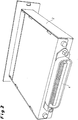
- a distributor module according to the invention 1 is shown in front view, wherein the well-connected terminal housing 2 and the front sockets 3, running in this figure as RJ-45 sockets, are shown.
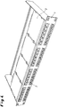
- Fig. 2 shows a distribution module according to the invention 1 with all sides closed housing 2 from the back, whereby the connector 4 can be seen.
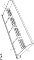
- FIG. 3 an inventive distribution module is shown with removed housing top, from which the nature of the internal connection of the front sockets 3 with the connector 4 can be seen.
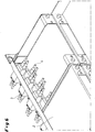
- Fig. 4 shows a distributor panel 5 according to the invention with 8 distributor modules 1 according to the invention with housing 2 closed on all sides, wherein the distributor modules are arranged in two rows one above the other and each have six connection sockets 3 on the front side.
- Fig. 5 the distribution panel 5 is shown in rear view, which in turn the connector 4 are clearly visible. Also recognizable is the installation of the distributor modules 1 with the housing 2 closed on all sides.
- Fig. 6 shows an inventive distribution module 1 with connection sockets 3 and 4 connectors on the back for connection and connection of optical fiber cables.
- This in Fig. 6 Distributor module 1 shown is installed in a distribution panel 5.
- the connectors 4 on the back of the distribution modules 1 may already be provided with fixed connection cables, but it is also possible to subsequently attach appropriate cables to the connectors 4.
- a connection of the front connector sockets with the connector on the back can be done via a circuit board.
- the immovable attachment of the connector 4 and the existing inside the housing fixed connection of the connector 4 with the connection sockets 3 ensures that even with a change of connection cables or a change in the configuration a complete and good contact is achieved. This makes the distribution modules and distribution panels according to the invention very flexible in practical application.
- connection sockets 3 which can be arbitrarily chosen in their design in a manner known to those skilled in the art.
- the distribution systems constructed in this way also have a high degree of flexibility in the case of configuration changes.
Description
Die vorliegende Erfindung betrifft Verteilermodule zur Verwendung in modularen Verteilerfeldern zur Verbindung analog oder digital beschalteter Anschlussbuchsen mit weiteren Verteilerfeldern, weiterführenden Leitungen oder Endgeräten, wobei das Verteilermodul mehrere Anschlussbuchsen an einer Frontseite aufweist. Darüber hinaus betrifft die vorliegende Erfindung modulare Verteilerfelder, die erfindungsgemäße Verteilermodule enthalten.The present invention relates to distribution modules for use in modular distribution panels for connecting analog or digitally wired connection sockets with further distribution fields, continuing lines or terminals, wherein the distribution module has a plurality of connection sockets on a front side. Moreover, the present invention relates to modular distribution panels containing distribution modules according to the invention.
Aus der
Aus der
Das Dokument
Erfindungsgemäß werden diese Nachteile des vorstehend beschriebenen Standes der Technik dadurch überwunden, dass Verteilermodule gemäß Oberbegriff des Anspruchs 1 zur Verfügung gestellt werden, wobei das Verteilermodul (1) mehrere Einzelmodule mit jeweils eigenem allseits geschlossenes Gehäuse oder mehrere Anschlussbuchsen (3) mit allseits geschlossenem Gehäuse (2) um die Mehrheit der Anschlussbuchsen (3) aufweist und auf der der Frontseite gegenüberliegenden Rückseite ein Steckverbinder (4) angeordnet ist, welcher durch eine entsprechende Verkabelung im Gehäuse (2) mit den mehreren Anschlussbuchsen (3) an der Frontseite des Verteilermoduls (1) verbunden istAccording to the invention, these disadvantages of the prior art described above are overcome by providing distributor modules according to the preamble of claim 1, wherein the distributor module (1) comprises a plurality of individual modules, each with its own closed housing or several connection sockets (3) with the housing completely closed on all sides ( 2) around the majority of the connection sockets (3) and on the front side opposite a connector (4) is arranged, which by a corresponding wiring in the housing (2) with the plurality of connection sockets (3) on the front side of the distributor module (1 ) connected is
Durch die Verwendung eines allseits geschlossenen Gehäuses wird die für die Erzielung hoher Datenübertragungsraten zwingend erforderliche gute Abschirmung erreicht. Dies kann noch durch die Verwendung entsprechend hoch abgeschirmter Kabel im Innern des Gehäuses unterstützt werden. Damit lassen sich mit den erfindungsgemäßen Verteilermodulen Übertragungsgeschwindigkeiten erreichen, wie sie in heute üblichen modernen sog. Gigabyte-Netzwerken gefordert werden (Performance nach Klassifizierung Cat. 5 e oder Cat. 6 oder besser).The use of a housing which is closed on all sides achieves the good shielding required for achieving high data transmission rates. This can be further supported by the use of appropriately shielded cables inside the housing. In this way, transmission speeds can be achieved with the distributor modules according to the invention, as required in today's modern so-called gigabyte networks (performance according to classification Cat. 5 e or Cat. 6 or better).
Unter Einzelmodul wird im folgenden ein allseits geschlossenes Element mit einer Anschlussbuchse an einer Frontseite und der Möglichkeit einer Verkabelung an der der Frontseite gegenüberliegenden Rückseite verstanden. Als Verteilermodul wird im Unterschied dazu ein Element verstanden, welches mehrere Anschlussbuchsen an einer Frontseite aufweist und eine gemeinsamen Verkabelung aller Anschlussbuchsen des Verteilermoduls an der der Frontseite entgegengesetzten Rückseite erlaubt. Ein Verteilermodul kann demzufolge aus mehreren entsprechend zueinander angeordneten Einzelmodulen mit jeweils eigenem allseits geschlossenem Gehäuse bestehen, ohne dass um diese Mehrheit an Einzelmodulen noch ein weiteres allseits geschlossenes Gehäuse zwingend erforderlich ist; durch die Verwendung eines solchen allseits geschlossenen Gehäuses können jedoch Vorteile erzielt werden, weshalb dies eine bevorzugte Ausführungsform darstellt. Alternativ kann ein Verteilermodul auch mehrere Anschlussbuchsen ohne eigenes allseits geschlossenes Gehäuse für jede einzelne Anschlussbuchse aufweisen, wobei ein allseits geschlossenes Gehäuse um diese mehrere Anschlussbuchsen des Verteilermoduls vorhanden ist.In the following, a single module is understood to mean an element which is closed on all sides and has a connection socket on a front side and the possibility of cabling on the rear side opposite the front side. In contrast, a distributor module is understood to be an element which has a plurality of connection sockets on a front side and allows common connection of all connection sockets of the distributor module to the rear side opposite the front side. Consequently, a distributor module can consist of a plurality of mutually corresponding individual modules, each with its own closed housing, without the need for this majority of individual modules nor another on all sides closed housing is mandatory; however, advantages can be achieved by the use of such a generally closed housing, which is why this is a preferred embodiment. Alternatively, a distribution module can also have several sockets without own well-closed housing for each individual connection socket, with a housing closed on all sides is present around these multiple connection sockets of the distribution module.
Ein weiterer Gegenstand der vorliegenden Erfindung sind modulare Verteilerfelder, die eines oder mehrere erfindungsgemäße Verteilermodule enthalten.Another object of the present invention are modular distribution panels containing one or more distribution modules according to the invention.
Bevorzugte Ausführungsformen der vorliegenden Erfindung ergeben sich aus der nachfolgenden Beschreibung und den Unteransprüchen.Preferred embodiments of the present invention will become apparent from the following description and subclaims.
Gemäß einer ersten bevorzugten Ausführungsform werden in den erfindungsgemäßen Verteilermodulen Einzelmodule mit einem allseits geschlossenen Gehäuse eingesetzt. Jedes dieser Einzelmodule ist durch sein eigenes allseits geschlossene Gehäuse sehr gut abgeschirmt, was hohe Datenvolumina und Übertragungsgeschwindigkeiten ermöglicht, wie sie in modernen Netzwerken heute verlangt werden. Bei dieser Ausführungsform sind bevorzugt mehrere der Einzelmodule rückseitig derartig zueinander angeordnet, dass der Steckverbinder mit einer Verkabelung mit den Anschlussbuchsen all dieser so zueinander angeordneten Einzelmodule an der Frontseite verbunden ist. Die erwähnte relative Anordnung der Einzelmodule zueinander muss dabei lediglich sicherstellen, dass über einen Steckverbinder eine Verbindung mit den Anschlussbuchsen mehrerer Einzelmodule möglich ist. Von diesem Erfordernis abgesehen, kann die Verknüpfung der Module beliebig erfolgen und an bauliche oder andere Anforderungen flexibel angepasst werden.According to a first preferred embodiment, individual modules with a housing which is closed on all sides are used in the distributor modules according to the invention. Each of these individual modules is very well shielded by its own fully enclosed housing, which allows high data volumes and transmission speeds, as required in modern networks today. In this embodiment, preferably a plurality of the individual modules are arranged on the rear side in such a manner that the plug connector is connected to a cabling with the connection sockets of all these so arranged to each other individual modules on the front. The mentioned relative arrangement of the individual modules to each other must only ensure that a connector with a connection to the sockets of several individual modules is possible. Apart from this requirement, the linking of the modules can be arbitrary and flexibly adapted to structural or other requirements.
Gemäß einer besonders bevorzugten Ausführungsform können mehrere solcher Einzelmodule zusammen beispielsweise in einem eigenen allseits geschlossenen Gehäuse untergebracht werden, was die Abschirmung und damit die anwendungstechnischen Eigenschaften weiter verbessert. Module gemäß dieser Ausführungsform unterscheiden sich rein äußerlich nicht von den erfahrungsgemäßen Verteilermodulen gemäß der nachstehend beschriebenen weiteren bevorzugten Ausführungsform.According to a particularly preferred embodiment, a plurality of such individual modules can be accommodated together, for example, in their own housing which is closed on all sides, which further improves the shielding and thus the performance properties. Modules according to this embodiment do not differ purely externally from the inventive distributor modules according to the further preferred embodiment described below.
Gemäß einer weiteren bevorzugten Ausführungsform weist das erfindungsgemäße Verteilermodul an der Frontseite mehrere Anschlussbuchsen auf (vorzugsweise in Form von dem Fachmann an sich bekannten RJ 45-Anschlussbuchsen). Bevorzugt weisen die erfindungsgemäßen Verteilermodule bei dieser Ausführungsform bis zu 6 Anschlussbuchsen, vorzugsweise bis zu 6 RJ45-Buchsen in einer Reihe auf. Dabei können die Module bei einer Einbauhöhe von 1 HE ein- oder zweireihig gestaltet sein. Weiterhin ist es aufgrund der flachen Bauweise gemäß einer bevorzugten Ausführungsform der erfindungsgemäßen Verteilermodule auch möglich zwei Verteilermodule bei einer Gesamt-Einbauhöhe von 1 HE übereinander anzuordnen. Dabei können zwei gleiche Verteilermodule eingesetzt werden oder aber zwei unterschiedliche Verteilermodule mit unterschiedlichen Anschlusstechniken übereinander angeordnet werden, ohne dass die Gesamthöhe von 1 HE überschritten wird.According to a further preferred embodiment, the distribution module according to the invention on the front side a plurality of connection sockets (preferably in the form of the person skilled in the known RJ 45 connection sockets). In this embodiment, the distributor modules according to the invention preferably have up to 6 connection sockets, preferably up to 6 RJ45 sockets in a row. The modules can be designed with an installation height of 1 U in one or two rows. Furthermore, due to the flat design according to a preferred embodiment of the distributor modules according to the invention also possible to arrange two distribution modules at a total installation height of 1 HE one above the other. Two identical distribution modules can be used or two different distribution modules with different connection techniques can be arranged one above the other without exceeding the total height of 1 U.
Grundsätzlich sind auch Verteilermodule mit einer Einbauhöhe von mehr als 1 HE möglich, was insbesondere bei der Gestaltung von Verteilermodulen mit internen Konvertern zum Übergang zwischen verschiedenartigen Verbindungsmöglichkeiten an Front- und Rückseite der erfindungsgemäßen Verteilermodule von Vorteil sein kann.Basically, distribution modules with an installation height of more than 1 U are possible, which is especially in the design of distribution modules with internal converters for the transition between different types of connection options on the front and back of the distributor modules according to the invention may be advantageous.
Für eine vollständige digitale Beschaltung von RJ45-Anschlussbuchsen werden 8 Anschlussadern benötigt. Daher muss der Steckverbinder entsprechend der Anzahl an zu verbindenden Anschlussbuchsen eine entsprechende Anzahl von Polen aufweisen. Bei einem Modul mit 6 RJ45-Anschlussbuchsen sind zur vollständigen digitalen Beschaltung mindestens 48 Pole erforderlich; es kann jedoch auch jede beliebige andere Zahl von Anschlussbuchsen mit einem Steckverbinder mit der entsprechenden Anzahl von Polen verbunden werden..For complete digital wiring of RJ45 sockets, 8 connection wires are required. Therefore, the connector must have a corresponding number of poles according to the number of connection sockets to be connected. For a module with 6 RJ45 sockets, at least 48 pins are required for complete digital wiring; however, any other number of receptacles may be connected to a connector having the corresponding number of poles.
Eine weitere bevorzugte Ausführungsform der erfindungsgemäßen Verteilermodule weist an der Frontseite mehrere Anschlussmöglichkeiten für optische Lichtwellenleiterkabel auf. Wie vorstehend allgemein beschrieben, kann das Verteilermodul mehrere Einzelmodule mit jeweils eigenem allseits geschlossenen Gehäuse enthalten oder aber eine Mehrheit von Anschlussbuchsen ohne eigenes Gehäuse für jede Buchse, aber allseits geschlossenem Gehäuse um die Gesamtheit der Buchsen.. In diesem Fall handelt es sich bei dem rückwärtigen Steckverbinder im erfindungsgemäßen Verteilermodul entsprechend um eine Anschlussmöglichkeit für optische Lichtwellenleiterkabel. Bei dieser Ausführungsform sind eine Vielzahl von Gestaltungsmöglichkeiten gegeben und es können eine Vielzahl von Lichtwellenleiter-Verbindungen pro Verteilermodul zur Verfügung gestellt werden. In diesem Zusammenhang sind dem Fachmann beispielsweise sogenannte MPO-Steckverbindungen für Lichtwellenleiterkabel bekannt, die es ermöglichen in einem erfindungsgemäßen Verteilermodul der Höhe 1/2 HE 72 und mehr Lichtwellenleiterverbindungen unterzubringen. Bei einer Einbaubreite von 19 " sind vier solcher Verteilermodule nebeneinander platzierbar, so dass in einem einzigen Verteiler mehr als 288 Verbindungen hergestellt werden können bzw. falls zwei Reihen an Verteilermodulen bei Bauhöhe 1 HE übereinander angeordnet werden, sogar bis zu 576 Verbindungen.A further preferred embodiment of the distributor modules according to the invention has on the front side several connection possibilities for optical fiber optic cables. As generally described above, the distribution module may include a plurality of individual modules, each with its own closed housing or a majority of sockets without their own housing for each socket, but on all sides closed housing to the entirety of the sockets .. In this case, it is in the rear Connector in the distribution module according to the invention according to a connection option for optical fiber optic cable. In this embodiment, a variety of design options are given and it can be provided a plurality of optical fiber connections per distribution module. In this context, the person skilled in the art, for example, so-called MPO connectors for optical fiber cables are known, which allow in a distribution module according to the invention the height 1/2 HE 72 and accommodate more fiber optic connections. With a mounting width of 19 ", four such distribution modules can be placed next to each other, so that more than 288 connections can be made in a single distribution box or if two rows of distribution modules are stacked 1U high, even up to 576 connections.
Die erfindungsgemäßen Verteilerfelder weisen ein oder mehrere erfindungsgemäße Verteilermodule auf. Dabei können auch gemischte Verteilerfelder zur Anwendung kommen, die erfindungsgemäße Verteilermodule mit Verbindungsmöglichkeiten über optische Lichtwellenleiter neben Verbindungsmöglichkeiten über konventionelle RJ45-Anschlussbuchsen bieten. Durch die innerhalb des Gehäuses des Verteilermoduls vorhandene feste Verkabelung der frontseitigen Anschlussbuchsen mit der rückseitigen Steckverbindung und der Ausführung des Verteilermoduls mit einem allseits geschlossenen Gehäuse ist diese gemischte Anordnung verschiedener Verteilermodule problemlos möglich, was einen weiteren Vorteil der erfindungsgemäßen Verteilerfelder darstellt. Die Anordnung der unterschiedlichen Verteilermodule im erfindungsgemäßen Verteilerfeld kann dabei nebeneinander oder aber, ohne die Einbauhöhe 1 HE zu überschreiten, auch übereinander erfolgen.The distributor fields according to the invention have one or more distributor modules according to the invention. In this case, mixed distribution panels can be used, provide the distribution module according to the invention with connection options via optical fibers in addition to connectivity options over conventional RJ45 sockets. Due to the existing within the housing of the distribution module fixed wiring of the front sockets with the rear connector and the design of the distribution module with a fully enclosed housing this mixed arrangement of different distribution modules is easily possible, which represents a further advantage of the distribution panels according to the invention. The arrangement of the different distribution modules in the distribution panel according to the invention can be done side by side or else, without exceeding the installation height 1 HE, also one above the other.
Eine weitere vorteilhafte Möglichkeit ist der Einsatz sogenannter Konvertermodule, d.h. erfindungsgemäßen Verteilermodulen, die rückseitig einen Anschluss von Lichtwellenleitern ermöglichen und an der Frontseite RJ 45 Buchsen aufweisen oder aber eine Gestaltung mit RJ 45 Anschlussmöglichkeit, vorzugsweise über Centronics-Kabel an der Rückseite und einer Anschlussmöglichkeit für Lichtwellenleiterkabel an der Frontseite des Moduls. Bei dieser Ausführungsform enthält das Modul im Innern des allseits geschlossenen Gehäuses die erforderlichen aktiven Komponenten zur Realisierung dieser Anschlussmöglichkeit.Another advantageous possibility is the use of so-called converter modules, i. distributor modules according to the invention, the rear side allow a connection of optical fibers and have on the front RJ 45 sockets or a design with RJ 45 connection option, preferably via Centronics cable on the back and a connection option for fiber optic cable on the front of the module. In this embodiment, the module contains the necessary active components in the interior of the generally closed housing for the realization of this connection possibility.
Die erfindungsgemäßen Verteilerfelder können zur Verbindung mehrerer Verteileranlagen, zum Anschluss weiterführender Leitungen oder aber zum Anschluss von Endgeräten dienen. Besonders eignen sie sich zur einfachen Herstellung von festen oder mobilen Gebäudeverkabelungen, da die Zahl der einzubringenden Kabel und der im Verteilerfeld aufzulegenden Kabel minimiert ist.The distributor fields according to the invention can be used to connect a plurality of distribution systems, to connect further lines or to connect terminals. They are particularly suitable for the simple production of fixed or mobile building cabling, since the number of cables to be inserted and the cable to be laid in the distribution panel is minimized.
Als besonderer technisch relevanter Vorteil ist hervorzuheben, dass mit den erfindungsgemäßen Verteilerfeldern unter Verwendung der erfindungsgemäßen Verteilermodule bei einer Einbauhöhe von 1 HE und einer Einbaubreite von 19" aufgrund der guten Abschirmung 48 voll beschaltete RJ45-Verbindungen mit einer Performance gemäß Cat.5 e bzw. Cat.6 oder besser möglich sind, was bislang nicht erreicht werden konnte.As a special technically relevant advantage is to be emphasized that with the distribution panels according to the invention using the distributor modules according to the invention at a height of 1 U and a mounting width of 19 "due to the good shield 48 fully wired RJ45 connections with a Performance according to Cat.5 e or Cat.6 or better are possible, which could not be achieved so far.
Um die mit dem Verteilermodul bzw. den Verteilerfeldern, die die erfindungsgemäßen Verteilermodule enthalten, erreichten hohen Abschirmungsgrad auch bei der weiterführenden Verkabelung aufrecht zu erhalten, ist es vorteilhaft, hochwertig abgeschirmte Verteilerkabel mit den entsprechenden Kabelverbindungen zu verwenden. Entsprechende Kabel dieser Art sind dem Fachmann an sich bekannt und im Handel erhältlich.In order to maintain the high degree of shielding achieved with the distributor module or the distributor fields, which contain the distributor modules according to the invention, also in the case of the continuing cabling, it is advantageous to use high-quality shielded distribution cables with the corresponding cable connections. Corresponding cables of this type are known in the art and commercially available.
Vorzugsweise werden zur Verbindung von Verteilermodulen mit RJ45-Anschlussbuchsen sog. Centronic-Verbindungskabel verwendet, die mindestens 48 Pole aufweisen und darüber hinaus einen hohen Abschirmungsgrad.Preferably, to connect distributor modules with RJ45 sockets, so-called Centronic connection cables are used which have at least 48 poles and moreover a high degree of shielding.
Die erfindungsgemäßen Verteilermodule und Verteilerfelder können auf vielfältige Weise in bestehende Einrichtungen zur Verkabelung integriert werden. So ist eine Montage auf sogenannten Hutschienen ebenso denkbar wie die einfache Integration in Standard Baugruppenträgern, insbesondere solchen mit der Breite 19 ". Die Anordnung der erfindungsgemäßen Verteilermodule bzw. Verteilerfelder kann dabei horizontal oder vertikal erfolgen, abhängig von den vorgegebenen baulichen Gegebenheiten. Entsprechende Montagesyteme und Möglichkeiten sind dem Fachmann an sich bekannt. Nur beispielhaft seien hier Befestigungssysteme mit sogenannten Clip-Verbindern genannt, die ein einfaches wechseln von Modulen möglich machen.The distributor modules and distribution panels according to the invention can be integrated in many ways into existing devices for cabling. Thus, an assembly on so-called top hat rails is just as conceivable as the simple integration in standard racks, especially those with the width 19 ".The arrangement of the distribution modules according to the invention distribution panels or can be done horizontally or vertically, depending on the given structural conditions Possibilities are known per se to the person skilled in the art, for example fastening systems with so-called clip connectors, which make a simple exchange of modules possible.
Durch den geringen Raumbedarf der erfindungsgemäßen Verteilermodule und der Verteilerfelder lassen diese sich auch insbesondere in sogenannten Bodentanks oder in Kabelkanälen einsetzen. Auch in sogenannten Consolidation points können die erfindungsgemäßen Verteilermodule bzw. Verteilerfelder vorteilhaft eingesetzt werden. Bei all diesen Anwendungen wirkt sich die Flexibilität, die mit den erfindungsgemäßen Modulen bei gleichzeitig geringem Raumbedarf erreicht wird, wirtschaftlich vorteilhaft für die Kosten einer Systemverkabelung aus. Zudem können in Bodentanks oder Kabelkanälen bei gleichem Raumbedarf eine höhere Anzahl von Anschlussbuchsen platziert werden, als dies bislang der Fall war. Auch dies hat wirtschaftliche Vorteile, da damit mehr Teilnehmer bei gleichem Platz- und Raumbedarf vernetzt werden können, als dies bislang möglich war. Bodentanks und Kabelkanäle sind dem Fachmann an sich bekannt und in der einschlägigen Literatur beschrieben, so dass sich hier weitere Ausführungen erübrigen. Prinzipiell sind die erfindungsgemäßen Verteilermodule bzw. Verteilerfelder in jeder beliebigen Art von Kabelkanal oder Bodentank verwendbar.Due to the small space requirement of the distributor modules according to the invention and the distribution fields, these can also be used in particular in so-called floor tanks or in cable ducts. Even in so-called consolidation points, the distributor modules or distribution panels according to the invention can be used advantageously. In all these applications, the flexibility that is achieved with the modules according to the invention with low space requirements, economically advantageous for the cost of a system cabling from. In addition, you can In floor tanks or cable channels with the same space requirements, a higher number of connection sockets are placed, as was previously the case. This also has economic advantages, since it allows more participants to be networked with the same space and space requirements than was previously possible. Floor tanks and cable ducts are known per se to those skilled in the art and described in the relevant literature, so that further explanations are unnecessary here. In principle, the distributor modules or distribution panels according to the invention can be used in any type of cable channel or floor tank.
Auch Systeme mit sogenannten Consolidation points sind dem Fachmann an sich bekannt und in der Literatur beschrieben, so dass sich nähere Angaben hier erübrigen. Wiederum können die erfindungsgemäßen Verteilermodule bzw. Verteilerfelder in beliebigen derartigen Systemlösungen eingesetzt werden.Even systems with so-called consolidation points are known per se to the person skilled in the art and described in the literature, so that further details are unnecessary here. Again, the distributor modules or distribution panels according to the invention can be used in any such system solutions.
Die Erfindung wird nachstehend anhand der beigefügten Abbildungen näher erläutert. Dabei zeigen:
- Fig 1 -
- die Frontansicht eines erfindungsgemäßen Verteilermoduls
- Fig. 2 -
- die Rückansicht eines erfindungsgemäßen Verteilermoduls
- Fig. 3 -
- ein Verteilermodul mit abgenommener Gehäuseoberseite
- Fig. 4 -
- ein Verteilerfeld mit 8 erfindungsgemäßen Verteilermodulen von der Vorderseite betrachtet
- Fig. 5 -
- ein Verteilerfeld mit 8 erfindungsgemäßen Verteilermodulen von der Rückseite betrachtet und
- Fig. 6 -
- ein Verteilermodul zur Verbindung mit optischen Lichtwellenleiterkabeln.
- Fig. 1 -
- the front view of a distributor module according to the invention
- Fig. 2 -
- the rear view of a distributor module according to the invention
- Fig. 3 -
- a distributor module with removed housing top
- Fig. 4 -
- a distribution panel with 8 distributor modules according to the invention viewed from the front
- Fig. 5 -
- a distribution panel with 8 distribution modules of the invention viewed from the back and
- Fig. 6 -
- a distributor module for connection to optical fiber cables.
In
In
In
Die Steckverbinder 4 an der Rückseite der Verteilermodule 1 können bereits mit festen Anschlusskabeln versehen sein, es ist jedoch auch genauso möglich, entsprechende Kabel nachträglich an den Steckverbindern 4 anzubringen. Alternativ kann auch eine Verbindung der frontseitigen Anschlussbuchsen mit dem Steckverbinder an der Rückseite über eine Platine erfolgen. Durch die unverrückbare Anbringung der Steckverbinder 4 und die im Gehäuseinneren vorhandene feste Verbindung der Steckverbindung 4 mit den Anschlussbuchsen 3 ist sichergestellt, dass auch bei einem Wechsel von Anschlusskabeln oder einer Änderung der Konfiguration eine vollständige und gute Kontaktierung erreicht wird. Dies macht die erfindungsgemäßen Verteilermodule und Verteilerfelder in der praktischen Anwendung sehr flexibel.The
Die Erfindung ist vorstehend anhand einiger Ausführungsformen beschrieben; sie ist aber nicht auf diese Ausführungsformen beschränkt. Wesentlich ist, dass durch die gehäuseinnere Verbindung von Steckverbindern 4 mit Anschlussbuchsen 3, die in ihrer Gestaltung beliebig in dem Fachmann bekannter Weise gewählt werden können, eine einfache und schnelle Verkabelung auch bei komplexen Verkabelungssituationen erreicht werden kann. Auch besitzen die so aufgebauten Verteilersysteme eine hohe Flexibilität bei Änderungen der Konfiguration.The invention is described above with reference to some embodiments; but it is not limited to these embodiments. It is essential that a simple and fast cabling can be achieved even in complex cabling situations by the inner housing connection of
Claims (10)
- Distribution module for the use in modular distribution panels (5) for connecting analogously or digitally switched connection sockets (3) with other distribution panels (5) or continuing lines or terminal devices, the distribution module comprising a plurality of connection sockets (3) at one front side characterised in that the distribution module (1) has a plurality of single modules with each having a housing (2) which is closed at all sides or a plurality of connection sockets (3) with a housing (2) which is closed at all sides, around the plurality of the connection sockets (3) and in that on the back side opposite to the front side a connector (4) is arranged which is connected by way of a corresponding wiring in the housing (2) with the plurality of the connection sockets (3) at the front side of the distribution module (1).
- Distribution module as claimed in claim 1 comprising a plurality of single modules with each having a connecting socket at the front side.
- Distribution module as claimed in claim 1 comprising a plurality of connection sockets at the front side.
- Distribution module as claimed in any of claims 1 - 3, characterised in that the connection sockets (3) are RJ 45 connection sockets.
- Distribution module as claimed in any of claims 1 to 4 characterised in that the connector (4) is a connector of the type Centronics with at least 48 poles.
- Distribution module as claimed in any of claims 1- 3, characterised in that the connection sockets (3) are connection sockets for the connection of optical fibre cables.
- Distribution module as claimed in claim 6, characterised in that the connector (4) is a connector for the connection of optical fibre cables.
- Modular Distribution panel for the connection with other modular distribution panels or continuing lines or terminal devices characterised in that it comprises one or more distribution modules according to any of claims 1 to 7.
- Distribution panel as claimed in claim 8, characterised in that at a paving width of 19 inches and an installation height of 1 HE it comprises up to 8 distribution modules as claimed in any of claims 1 to 7.
- Use of the distribution modules as claimed in any of claims 1 to 7 or of the distribution panels according to any of claims 8 or 9 in cable channels, ground tanks or consolidation points at the immobile or mobile structured cabling.
Applications Claiming Priority (2)
| Application Number | Priority Date | Filing Date | Title |
|---|---|---|---|
| DE202008001740U DE202008001740U1 (en) | 2008-02-07 | 2008-02-07 | Distribution module and modular distribution panel |
| PCT/EP2009/051382 WO2009098293A1 (en) | 2008-02-07 | 2009-02-06 | Distribution module, and modular distribution panel |
Publications (2)
| Publication Number | Publication Date |
|---|---|
| EP2241114A1 EP2241114A1 (en) | 2010-10-20 |
| EP2241114B1 true EP2241114B1 (en) | 2017-05-17 |
Family
ID=39587672
Family Applications (2)
| Application Number | Title | Priority Date | Filing Date |
|---|---|---|---|
| EP09708494.1A Active EP2241115B1 (en) | 2008-02-07 | 2009-02-06 | Distribution module, and modular distribution panel |
| EP09707334.0A Active EP2241114B1 (en) | 2008-02-07 | 2009-02-06 | Distribution module, and modular distribution panel |
Family Applications Before (1)
| Application Number | Title | Priority Date | Filing Date |
|---|---|---|---|
| EP09708494.1A Active EP2241115B1 (en) | 2008-02-07 | 2009-02-06 | Distribution module, and modular distribution panel |
Country Status (3)
| Country | Link |
|---|---|
| EP (2) | EP2241115B1 (en) |
| DE (2) | DE202008001740U1 (en) |
| WO (2) | WO2009098293A1 (en) |
Families Citing this family (3)
| Publication number | Priority date | Publication date | Assignee | Title |
|---|---|---|---|---|
| DE102012102242B3 (en) * | 2012-03-16 | 2013-09-12 | Phoenix Contact Gmbh & Co. Kg | Arrangement as a modular distribution panel and method for its assembly |
| DE202017105561U1 (en) | 2017-09-14 | 2017-11-24 | Tde - Trans Data Elektronik Gmbh | Arrangement of distribution modules |
| CN114156773B (en) * | 2021-11-18 | 2022-12-30 | 国网安徽省电力有限公司滁州供电公司 | High-voltage distribution network cable inspection device |
Citations (1)
| Publication number | Priority date | Publication date | Assignee | Title |
|---|---|---|---|---|
| DE102004043763B3 (en) * | 2004-09-10 | 2006-02-02 | Adc Gmbh | Distribution module for conversion between balanced and unbalanced data transmission links |
Family Cites Families (9)
| Publication number | Priority date | Publication date | Assignee | Title |
|---|---|---|---|---|
| ES2197902T3 (en) * | 1993-09-06 | 2004-01-16 | Quante Aktiengesellschaft | DISTRIBUTOR FOR TELEPHONE, SIGNAL, CONTROL OR SIMILAR CABLES. |
| DE29510185U1 (en) | 1995-06-23 | 1995-11-30 | Tkm Telekommunikation Und Elek | Distribution field |
| DE29913731U1 (en) | 1999-08-06 | 2000-01-05 | Tkm Telekommunikation Und Elek | Modular distribution panel |
| GB2402269A (en) * | 2003-04-28 | 2004-12-01 | Nigel Weepers | Switched telecommunications connection device |
| DE10339844B3 (en) * | 2003-08-29 | 2005-01-27 | Krone Gmbh | Splitter connection module for telecommunications and data technology has a casing accessible from outside to hold input/output contacts to connect wires and cables |
| US7453706B2 (en) * | 2003-11-13 | 2008-11-18 | Adc Telecommunications, Inc. | Module with interchangeable card |
| DE10355017B4 (en) * | 2003-11-25 | 2007-05-24 | Adc Gmbh | Distribution device for communication and data technology |
| US7362590B2 (en) * | 2004-03-31 | 2008-04-22 | Adc Telecommunications, Inc. | Patch panel with modules |
| US7570487B2 (en) * | 2005-03-02 | 2009-08-04 | Adc Telecommunications, Inc. | Patch panel module and chassis |
-
2008
- 2008-02-07 DE DE202008001740U patent/DE202008001740U1/en not_active Expired - Lifetime
-
2009
- 2009-02-06 DE DE202009009969U patent/DE202009009969U1/en not_active Expired - Lifetime
- 2009-02-06 WO PCT/EP2009/051382 patent/WO2009098293A1/en active Application Filing
- 2009-02-06 EP EP09708494.1A patent/EP2241115B1/en active Active
- 2009-02-06 EP EP09707334.0A patent/EP2241114B1/en active Active
- 2009-02-06 WO PCT/EP2009/051381 patent/WO2009098292A1/en active Application Filing
Patent Citations (1)
| Publication number | Priority date | Publication date | Assignee | Title |
|---|---|---|---|---|
| DE102004043763B3 (en) * | 2004-09-10 | 2006-02-02 | Adc Gmbh | Distribution module for conversion between balanced and unbalanced data transmission links |
Also Published As
| Publication number | Publication date |
|---|---|
| WO2009098293A1 (en) | 2009-08-13 |
| DE202009009969U1 (en) | 2009-11-19 |
| WO2009098292A1 (en) | 2009-08-13 |
| DE202008001740U1 (en) | 2008-07-03 |
| EP2241115B1 (en) | 2017-05-17 |
| EP2241114A1 (en) | 2010-10-20 |
| EP2241115A1 (en) | 2010-10-20 |
Similar Documents
| Publication | Publication Date | Title |
|---|---|---|
| DE4402002B4 (en) | I / O modules / for a data bus | |
| EP1290901B1 (en) | Distribution device in a data signal processing installation, and data signal processing installation | |
| DE102006012730B3 (en) | An attachment system for attaching a cabin trim element to a support structure of an aircraft | |
| DE102014108847B4 (en) | connector module | |
| DE102011101686B4 (en) | System cabling for multiple relay arrangement | |
| EP0243296A1 (en) | Divider device, particularly for the main divider of telecommunication installations | |
| DE102010033545A1 (en) | Contacting devices i.e. displacement terminal-plug connectors, for contacting e.g. flat strip cable in bus system for motor car, has displacement terminal needed for address coding and clamped at electric conductors | |
| EP2862364B1 (en) | Distributor connection module | |
| EP2241114B1 (en) | Distribution module, and modular distribution panel | |
| EP3570392B1 (en) | Surge arrester arrangement with multiple surge arresters arranged in a housing and internal wiring for protecting low voltage power supply systems | |
| EP3323176A1 (en) | Plug connector assembly with coding | |
| EP0461454A2 (en) | Distribution device | |
| DE102020123465B4 (en) | Optoelectronic module, optoelectronic connector and optoelectronic sub-distribution | |
| DE10357468B4 (en) | Shunting or device connection cable for communication systems for use in networks | |
| EP3457708B1 (en) | Arrangement of distributor modules | |
| EP3048868B1 (en) | Communication unit | |
| DE202010008678U1 (en) | Socket for the electrical and mechanical connection of electrical conductors | |
| EP2710809B1 (en) | Distributor unit and a distributor block which comprises at least two distributor units | |
| DE102013009809A1 (en) | Modular device of electrical installation | |
| DE4337924A1 (en) | Apparatus for enabling multiple connection of data-processing terminals, in particular Ethernet hub | |
| EP1069784A2 (en) | Variable distributing connector | |
| WO2016162017A1 (en) | Connector module for a modular plug connector | |
| EP0720393A2 (en) | Communication system | |
| DE202015101777U1 (en) | Connector module for a modular connector | |
| DE202012102525U1 (en) | Patch field element |
Legal Events
| Date | Code | Title | Description |
|---|---|---|---|
| PUAI | Public reference made under article 153(3) epc to a published international application that has entered the european phase |
Free format text: ORIGINAL CODE: 0009012 |
|
| 17P | Request for examination filed |
Effective date: 20100830 |
|
| AK | Designated contracting states |
Kind code of ref document: A1 Designated state(s): AT BE BG CH CY CZ DE DK EE ES FI FR GB GR HR HU IE IS IT LI LT LU LV MC MK MT NL NO PL PT RO SE SI SK TR |
|
| AX | Request for extension of the european patent |
Extension state: AL BA RS |
|
| DAX | Request for extension of the european patent (deleted) | ||
| RAP3 | Party data changed (applicant data changed or rights of an application transferred) |
Owner name: TRANS DATA ELEKTRONIK GMBH |
|
| 17Q | First examination report despatched |
Effective date: 20150722 |
|
| GRAP | Despatch of communication of intention to grant a patent |
Free format text: ORIGINAL CODE: EPIDOSNIGR1 |
|
| STAA | Information on the status of an ep patent application or granted ep patent |
Free format text: STATUS: GRANT OF PATENT IS INTENDED |
|
| INTG | Intention to grant announced |
Effective date: 20161215 |
|
| GRAS | Grant fee paid |
Free format text: ORIGINAL CODE: EPIDOSNIGR3 |
|
| GRAA | (expected) grant |
Free format text: ORIGINAL CODE: 0009210 |
|
| STAA | Information on the status of an ep patent application or granted ep patent |
Free format text: STATUS: THE PATENT HAS BEEN GRANTED |
|
| AK | Designated contracting states |
Kind code of ref document: B1 Designated state(s): AT BE BG CH CY CZ DE DK EE ES FI FR GB GR HR HU IE IS IT LI LT LU LV MC MK MT NL NO PL PT RO SE SI SK TR |
|
| REG | Reference to a national code |
Ref country code: GB Ref legal event code: FG4D Free format text: NOT ENGLISH |
|
| REG | Reference to a national code |
Ref country code: CH Ref legal event code: EP |
|
| REG | Reference to a national code |
Ref country code: IE Ref legal event code: FG4D Free format text: LANGUAGE OF EP DOCUMENT: GERMAN |
|
| REG | Reference to a national code |
Ref country code: AT Ref legal event code: REF Ref document number: 895428 Country of ref document: AT Kind code of ref document: T Effective date: 20170615 |
|
| REG | Reference to a national code |
Ref country code: DE Ref legal event code: R096 Ref document number: 502009013976 Country of ref document: DE |
|
| REG | Reference to a national code |
Ref country code: NL Ref legal event code: MP Effective date: 20170517 |
|
| REG | Reference to a national code |
Ref country code: LT Ref legal event code: MG4D |
|
| PG25 | Lapsed in a contracting state [announced via postgrant information from national office to epo] |
Ref country code: ES Free format text: LAPSE BECAUSE OF FAILURE TO SUBMIT A TRANSLATION OF THE DESCRIPTION OR TO PAY THE FEE WITHIN THE PRESCRIBED TIME-LIMIT Effective date: 20170517 Ref country code: LT Free format text: LAPSE BECAUSE OF FAILURE TO SUBMIT A TRANSLATION OF THE DESCRIPTION OR TO PAY THE FEE WITHIN THE PRESCRIBED TIME-LIMIT Effective date: 20170517 Ref country code: NO Free format text: LAPSE BECAUSE OF FAILURE TO SUBMIT A TRANSLATION OF THE DESCRIPTION OR TO PAY THE FEE WITHIN THE PRESCRIBED TIME-LIMIT Effective date: 20170817 Ref country code: GR Free format text: LAPSE BECAUSE OF FAILURE TO SUBMIT A TRANSLATION OF THE DESCRIPTION OR TO PAY THE FEE WITHIN THE PRESCRIBED TIME-LIMIT Effective date: 20170818 Ref country code: HR Free format text: LAPSE BECAUSE OF FAILURE TO SUBMIT A TRANSLATION OF THE DESCRIPTION OR TO PAY THE FEE WITHIN THE PRESCRIBED TIME-LIMIT Effective date: 20170517 Ref country code: FI Free format text: LAPSE BECAUSE OF FAILURE TO SUBMIT A TRANSLATION OF THE DESCRIPTION OR TO PAY THE FEE WITHIN THE PRESCRIBED TIME-LIMIT Effective date: 20170517 |
|
| PG25 | Lapsed in a contracting state [announced via postgrant information from national office to epo] |
Ref country code: LV Free format text: LAPSE BECAUSE OF FAILURE TO SUBMIT A TRANSLATION OF THE DESCRIPTION OR TO PAY THE FEE WITHIN THE PRESCRIBED TIME-LIMIT Effective date: 20170517 Ref country code: SE Free format text: LAPSE BECAUSE OF FAILURE TO SUBMIT A TRANSLATION OF THE DESCRIPTION OR TO PAY THE FEE WITHIN THE PRESCRIBED TIME-LIMIT Effective date: 20170517 Ref country code: IS Free format text: LAPSE BECAUSE OF FAILURE TO SUBMIT A TRANSLATION OF THE DESCRIPTION OR TO PAY THE FEE WITHIN THE PRESCRIBED TIME-LIMIT Effective date: 20170917 Ref country code: BG Free format text: LAPSE BECAUSE OF FAILURE TO SUBMIT A TRANSLATION OF THE DESCRIPTION OR TO PAY THE FEE WITHIN THE PRESCRIBED TIME-LIMIT Effective date: 20170817 Ref country code: NL Free format text: LAPSE BECAUSE OF FAILURE TO SUBMIT A TRANSLATION OF THE DESCRIPTION OR TO PAY THE FEE WITHIN THE PRESCRIBED TIME-LIMIT Effective date: 20170517 Ref country code: PL Free format text: LAPSE BECAUSE OF FAILURE TO SUBMIT A TRANSLATION OF THE DESCRIPTION OR TO PAY THE FEE WITHIN THE PRESCRIBED TIME-LIMIT Effective date: 20170517 |
|
| PG25 | Lapsed in a contracting state [announced via postgrant information from national office to epo] |
Ref country code: SK Free format text: LAPSE BECAUSE OF FAILURE TO SUBMIT A TRANSLATION OF THE DESCRIPTION OR TO PAY THE FEE WITHIN THE PRESCRIBED TIME-LIMIT Effective date: 20170517 Ref country code: EE Free format text: LAPSE BECAUSE OF FAILURE TO SUBMIT A TRANSLATION OF THE DESCRIPTION OR TO PAY THE FEE WITHIN THE PRESCRIBED TIME-LIMIT Effective date: 20170517 Ref country code: DK Free format text: LAPSE BECAUSE OF FAILURE TO SUBMIT A TRANSLATION OF THE DESCRIPTION OR TO PAY THE FEE WITHIN THE PRESCRIBED TIME-LIMIT Effective date: 20170517 Ref country code: CZ Free format text: LAPSE BECAUSE OF FAILURE TO SUBMIT A TRANSLATION OF THE DESCRIPTION OR TO PAY THE FEE WITHIN THE PRESCRIBED TIME-LIMIT Effective date: 20170517 Ref country code: RO Free format text: LAPSE BECAUSE OF FAILURE TO SUBMIT A TRANSLATION OF THE DESCRIPTION OR TO PAY THE FEE WITHIN THE PRESCRIBED TIME-LIMIT Effective date: 20170517 |
|
| REG | Reference to a national code |
Ref country code: DE Ref legal event code: R097 Ref document number: 502009013976 Country of ref document: DE |
|
| PG25 | Lapsed in a contracting state [announced via postgrant information from national office to epo] |
Ref country code: IT Free format text: LAPSE BECAUSE OF FAILURE TO SUBMIT A TRANSLATION OF THE DESCRIPTION OR TO PAY THE FEE WITHIN THE PRESCRIBED TIME-LIMIT Effective date: 20170517 |
|
| PLBE | No opposition filed within time limit |
Free format text: ORIGINAL CODE: 0009261 |
|
| STAA | Information on the status of an ep patent application or granted ep patent |
Free format text: STATUS: NO OPPOSITION FILED WITHIN TIME LIMIT |
|
| 26N | No opposition filed |
Effective date: 20180220 |
|
| PG25 | Lapsed in a contracting state [announced via postgrant information from national office to epo] |
Ref country code: SI Free format text: LAPSE BECAUSE OF FAILURE TO SUBMIT A TRANSLATION OF THE DESCRIPTION OR TO PAY THE FEE WITHIN THE PRESCRIBED TIME-LIMIT Effective date: 20170517 |
|
| PG25 | Lapsed in a contracting state [announced via postgrant information from national office to epo] |
Ref country code: MC Free format text: LAPSE BECAUSE OF FAILURE TO SUBMIT A TRANSLATION OF THE DESCRIPTION OR TO PAY THE FEE WITHIN THE PRESCRIBED TIME-LIMIT Effective date: 20170517 Ref country code: MT Free format text: LAPSE BECAUSE OF FAILURE TO SUBMIT A TRANSLATION OF THE DESCRIPTION OR TO PAY THE FEE WITHIN THE PRESCRIBED TIME-LIMIT Effective date: 20170517 |
|
| REG | Reference to a national code |
Ref country code: IE Ref legal event code: MM4A |
|
| REG | Reference to a national code |
Ref country code: BE Ref legal event code: MM Effective date: 20180228 |
|
| PG25 | Lapsed in a contracting state [announced via postgrant information from national office to epo] |
Ref country code: LU Free format text: LAPSE BECAUSE OF NON-PAYMENT OF DUE FEES Effective date: 20180206 |
|
| REG | Reference to a national code |
Ref country code: FR Ref legal event code: ST Effective date: 20181031 |
|
| PG25 | Lapsed in a contracting state [announced via postgrant information from national office to epo] |
Ref country code: IE Free format text: LAPSE BECAUSE OF NON-PAYMENT OF DUE FEES Effective date: 20180206 |
|
| REG | Reference to a national code |
Ref country code: DE Ref legal event code: R082 Ref document number: 502009013976 Country of ref document: DE Representative=s name: MEISSNER BOLTE PATENTANWAELTE RECHTSANWAELTE P, DE |
|
| PG25 | Lapsed in a contracting state [announced via postgrant information from national office to epo] |
Ref country code: BE Free format text: LAPSE BECAUSE OF NON-PAYMENT OF DUE FEES Effective date: 20180228 Ref country code: FR Free format text: LAPSE BECAUSE OF NON-PAYMENT OF DUE FEES Effective date: 20180228 |
|
| REG | Reference to a national code |
Ref country code: AT Ref legal event code: MM01 Ref document number: 895428 Country of ref document: AT Kind code of ref document: T Effective date: 20180206 |
|
| PG25 | Lapsed in a contracting state [announced via postgrant information from national office to epo] |
Ref country code: AT Free format text: LAPSE BECAUSE OF NON-PAYMENT OF DUE FEES Effective date: 20180206 |
|
| PG25 | Lapsed in a contracting state [announced via postgrant information from national office to epo] |
Ref country code: TR Free format text: LAPSE BECAUSE OF FAILURE TO SUBMIT A TRANSLATION OF THE DESCRIPTION OR TO PAY THE FEE WITHIN THE PRESCRIBED TIME-LIMIT Effective date: 20170517 |
|
| PG25 | Lapsed in a contracting state [announced via postgrant information from national office to epo] |
Ref country code: PT Free format text: LAPSE BECAUSE OF FAILURE TO SUBMIT A TRANSLATION OF THE DESCRIPTION OR TO PAY THE FEE WITHIN THE PRESCRIBED TIME-LIMIT Effective date: 20170517 Ref country code: HU Free format text: LAPSE BECAUSE OF FAILURE TO SUBMIT A TRANSLATION OF THE DESCRIPTION OR TO PAY THE FEE WITHIN THE PRESCRIBED TIME-LIMIT; INVALID AB INITIO Effective date: 20090206 |
|
| REG | Reference to a national code |
Ref country code: DE Ref legal event code: R082 Ref document number: 502009013976 Country of ref document: DE Representative=s name: MEISSNER BOLTE PATENTANWAELTE RECHTSANWAELTE P, DE |
|
| PG25 | Lapsed in a contracting state [announced via postgrant information from national office to epo] |
Ref country code: MK Free format text: LAPSE BECAUSE OF NON-PAYMENT OF DUE FEES Effective date: 20170517 Ref country code: CY Free format text: LAPSE BECAUSE OF FAILURE TO SUBMIT A TRANSLATION OF THE DESCRIPTION OR TO PAY THE FEE WITHIN THE PRESCRIBED TIME-LIMIT Effective date: 20170517 |
|
| REG | Reference to a national code |
Ref country code: DE Ref legal event code: R055 Ref document number: 502009013976 Country of ref document: DE |
|
| PLCP | Request for limitation filed |
Free format text: ORIGINAL CODE: EPIDOSNLIM1 |
|
| PLCQ | Request for limitation of patent found admissible |
Free format text: ORIGINAL CODE: 0009231 |
|
| LIM1 | Request for limitation found admissible |
Free format text: SEQUENCE NO: 1; FILED AFTER OPPOSITION PERIOD Filing date: 20220408 Effective date: 20220414 |
|
| PLCR | Communication despatched that request for limitation of patent was allowed |
Free format text: ORIGINAL CODE: 0009245 |
|
| REG | Reference to a national code |
Ref country code: DE Ref legal event code: R056 Ref document number: 502009013976 Country of ref document: DE |
|
| PGFP | Annual fee paid to national office [announced via postgrant information from national office to epo] |
Ref country code: CH Payment date: 20230307 Year of fee payment: 15 |
|
| PGFP | Annual fee paid to national office [announced via postgrant information from national office to epo] |
Ref country code: GB Payment date: 20230214 Year of fee payment: 15 Ref country code: DE Payment date: 20230227 Year of fee payment: 15 |
|
| PLCM | Reason for rejection of request for limitation recorded |
Free format text: ORIGINAL CODE: EPIDOSNRJL1 |
|
| PLCL | Despatch of rejection of request for limitation |
Free format text: ORIGINAL CODE: EPIDOSNRJL2 |
|
| REG | Reference to a national code |
Ref country code: DE Ref legal event code: R451 Ref document number: 502009013976 Country of ref document: DE |
|
| REG | Reference to a national code |
Ref country code: DE Ref legal event code: R451 Ref document number: 502009013976 Country of ref document: DE |
|
| PLCV | Request for limitation of patent rejected |
Free format text: ORIGINAL CODE: 0009240 |
|
| RJL4 | Request for limitation rejected because rall (request allowed) requirements not fulfilled |
Free format text: SEQUENCE NO. 1; DECISION DESPATCHED ON 20230908 Effective date: 20230918 |