DE202008009847U1 - base support - Google Patents
base support Download PDFInfo
- Publication number
- DE202008009847U1 DE202008009847U1 DE200820009847 DE202008009847U DE202008009847U1 DE 202008009847 U1 DE202008009847 U1 DE 202008009847U1 DE 200820009847 DE200820009847 DE 200820009847 DE 202008009847 U DE202008009847 U DE 202008009847U DE 202008009847 U1 DE202008009847 U1 DE 202008009847U1
- Authority
- DE
- Germany
- Prior art keywords
- post
- foot
- screw
- plate
- support element
- Prior art date
- Legal status (The legal status is an assumption and is not a legal conclusion. Google has not performed a legal analysis and makes no representation as to the accuracy of the status listed.)
- Expired - Lifetime
Links
- 125000006850 spacer group Chemical group 0.000 claims abstract description 7
- 239000000758 substrate Substances 0.000 claims 1
- 238000011161 development Methods 0.000 description 3
- 230000018109 developmental process Effects 0.000 description 3
- BUHVIAUBTBOHAG-FOYDDCNASA-N (2r,3r,4s,5r)-2-[6-[[2-(3,5-dimethoxyphenyl)-2-(2-methylphenyl)ethyl]amino]purin-9-yl]-5-(hydroxymethyl)oxolane-3,4-diol Chemical compound COC1=CC(OC)=CC(C(CNC=2C=3N=CN(C=3N=CN=2)[C@H]2[C@@H]([C@H](O)[C@@H](CO)O2)O)C=2C(=CC=CC=2)C)=C1 BUHVIAUBTBOHAG-FOYDDCNASA-N 0.000 description 1
- 230000001419 dependent effect Effects 0.000 description 1
- 238000003780 insertion Methods 0.000 description 1
- 230000037431 insertion Effects 0.000 description 1
Classifications
-
- E—FIXED CONSTRUCTIONS
- E04—BUILDING
- E04H—BUILDINGS OR LIKE STRUCTURES FOR PARTICULAR PURPOSES; SWIMMING OR SPLASH BATHS OR POOLS; MASTS; FENCING; TENTS OR CANOPIES, IN GENERAL
- E04H12/00—Towers; Masts or poles; Chimney stacks; Water-towers; Methods of erecting such structures
- E04H12/22—Sockets or holders for poles or posts
- E04H12/2253—Mounting poles or posts to the holder
Landscapes
- Engineering & Computer Science (AREA)
- Architecture (AREA)
- Civil Engineering (AREA)
- Structural Engineering (AREA)
- Ladders (AREA)
Abstract
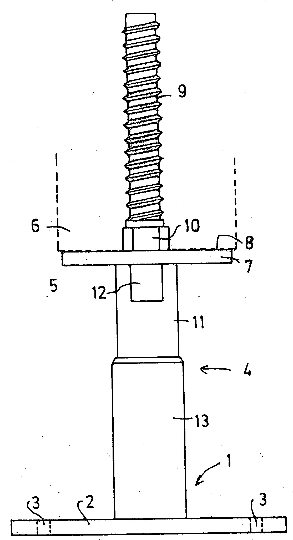
Stützenfuß zur
Abstützung von Holzpfosten (6), mit
1.1 einem Abstützelement
(5) zur Anbringung an dem unteren Ende des Pfostens (6),
1.2
einem Fußelement (1) zur Anbringung an dem Boden, sowie
mit
1.3 eine Abstandseinrichtung (4), die
1.4 einerseits
an der dem Pfosten (6) abgewandten Seite des Abstützelements
(5) und
1.5 andererseits an der Oberseite des Fußelements
(1) befestigt ist, wobei
1.6 das Abstützelement (5)
an seiner dem Pfosten (6) zugeordneten Oberseite (8) eine Schraube
(9) zum Einschrauben in ein von der Stirnfläche des Pfostens
(6) ausgehendes Loch und/oder
1.7 das Fußelement (1)
an seiner Bodenseite eine zum Einschrauben in ein Loch in einem
Untergrund bestimmte Schraube, insbesondere eine Betonschraube (15)
aufweist.Column foot for supporting wooden posts (6), with
1.1 a support element (5) for attachment to the lower end of the post (6),
1.2 a foot element (1) for attachment to the ground, as well as with
1.3 a spacer device (4), the
1.4 on the one hand on the post (6) facing away from the supporting element (5) and
1.5 on the other hand at the top of the foot member (1) is fixed, wherein
1.6 the support element (5) on its the post (6) associated upper side (8) has a screw (9) for screwing into a of the end face of the post (6) outgoing hole and / or
1.7, the foot element (1) on its bottom side a certain for screwing into a hole in a ground screw, in particular a concrete screw (15).
Description
Die Erfindung betrifft einen Stützenfuß, wie er zur Abstützung von Holzpfosten üblicherweise verwendet wird. Holzpfosten sollen an dem Boden einerseits ausreichend befestigt sein, andererseits auch einen gewissen Abstand von dem Boden aufweisen. Zu diesem Zweck sind Stützenfüße bekannt, die diesen Abstand bewirken und einerseits mit dem unteren Bereich des Holzpfostens und andererseits mit dem Boden verbunden sind. Der Boden ist normalerweise betoniert, so dass der Stützenfuß dort ein Fundament vorfindet. Am unteren Ende des Stützenfußes ist normalerweise eine Platte befestigt, die dann mit Schrauben, gegebenenfalls auch mit Dübeln, an dem Boden angeschraubt werden kann.The The invention relates to a column foot, as it relates to Support of wooden posts commonly used becomes. Wooden posts should be sufficiently attached to the ground on the one hand on the other hand also have a certain distance from the ground. To Column feet are known for this purpose. which cause this distance and on the one hand with the lower area the wooden post and on the other hand connected to the ground. The floor is usually concreted, leaving the column foot there finds a foundation. At the bottom of the column foot is usually a plate attached, which then with screws, possibly also with dowels, bolted to the ground can be.
Bei
einem bekannten Stützenfuß dieser Art ist ein
Abstützteil für den Holzpfosten vorgesehen, das
eine Platte mit einem senkrecht von der Platte nach oben ragenden
Zapfen aufweist. In eine Bohrung in der Stirnfläche des
Pfostens wird dieser Zapfen eingeschoben, bis die Pfostenstirnseite
auf der Platte aufliegt. Axial wird der Zapfen dann durch einen
Querzapfen gesichert, der durch den Pfosten hindurch in eine Öffnung
des Zapfens eingreift (
Die Befestigung des Abstützelements und damit des Stützenfußes ist bei den bekannten Lösungen aufwändig. Es sind mehrere Schrauben zur Fixierung nötig, außerdem muss ein Querloch gebohrt werden.The Fixing the support element and thus the column foot is complex in the known solutions. There are several screws needed for fixation, as well a transverse hole must be drilled.
Der Erfindung liegt die Aufgabe zu Grunde, einen Stützenfuß zu schaffen, der sich einfacher montieren lässt und der es ermöglicht, dass der Stützenfuß optisch wenig auffällt.Of the Invention is based on the object to a column foot create, which is easier to assemble and which it allows the column foot optically little noticeable.
Zur Lösung dieser Aufgabe schlägt die Erfindung einen Stützenfuß mit den im Anspruch 1 genannten Merkmalen vor. Weiterbildungen der Erfindung sind Gegenstand von Unteransprüchen.to Solution to this problem, the invention proposes a Column foot with the features mentioned in claim 1 in front. Further developments of the invention are the subject of dependent claims.
Zur Befestigung des Abstützelements des Stützenfußes an dem Holzpfosten wird etwa in der gleichen Art wie bisher ein Loch durch die Stirnfläche des Holzpfostens gebohrt. Anschließend kann das Abstützelement mithilfe der an ihm vorhandenen Schraube an der Stirnfläche des Holzpfostens festgeschraubt werden. Ein nachträgliches Sichern durch einen durch den Pfosten hindurchzuführenden Querzapfen ist nicht mehr erforderlich, da diese axiale Sicherung durch das Gewinde der Schraube gewährleistet wird.to Attachment of the support element of the column foot on the wooden post is about in the same way as before Hole drilled through the end face of the wooden post. Subsequently can the support element using the existing screw on it be screwed to the end face of the wooden post. A subsequent belay by one through the post to be passed through transverse pin is no longer necessary because this axial securing ensured by the thread of the screw becomes.
Bei dem Fußelement kann in ähnlicher Weise eine Befestigung an dem Untergrund erfolgen.at The foot element may similarly have a fastening done on the ground.
In Weiterbildung der Erfindung kann vorgesehen sein, dass das Abstützelement eine Platte aufweist, die eine der Stirnfläche des Pfostens entsprechende Form aufweist. Beim Festschrauben des Abstützelements kann auf diese Weise dafür gesorgt werden, dass das Abstützelement mit dieser Platte soweit mit den Pfosten verbunden wird, dass dessen Stirnfläche flächig auf der Oberseite dieser Platte aufliegt.In Further development of the invention can be provided that the support element a plate having one of the end face of the post has corresponding shape. When tightening the support element can be ensured in this way that the support element with this plate as far as the post is connected, that its end face flat on the top of this plate rests.
Da die Schraube, die das Abstützelement mit dem Pfosten verbindet, eine axiale Sicherung in beiden Richtungen gewährleistet, kann erfin dungsgemäß die Platte des Abstützelements kleiner sein als die Stirnfläche des Pfostens, so dass die Platte an keiner Seite über die Außenkontur des Pfostens vorsteht. Die Platte ist damit praktisch unsichtbar. Wenn man berücksichtigt, dass die Augenhöhe des normalen Betrachters, sei es im Stehen oder im Sitzen, deutlich über dem unteren Ende solcher Holzpfosten liegt, ist für ihn die Platte nicht zu sehen.There the screw that connects the support element to the post, ensures axial securing in both directions, can inven tion according to the plate of the support element be smaller than the end face of the post, so that the plate on each side of the outer contour projecting the post. The plate is thus virtually invisible. Taking into account that the eye level of the normal viewer, be it standing or sitting, well above the lower end of such wooden posts is for him not to see the plate.
In Weiterbildung der Erfindung kann vorgesehen sein, dass die erwähnte Schraube das einzige Befestigungsmittel zur Befestigung des Holzpfostens an dem Abstützelement ist.In Development of the invention can be provided that the mentioned Screw the only fastener for fixing the wooden post the support element is.
Bei der Anbringung des Fußelements am Boden, beispielsweise einem Betonboden, kann ebenfalls dafür gesorgt werden, dass das Fußelement nur geringfügig über die an ihm befestigte Abstandseinrichtung vorspringt. Es lässt sich also auch hier eine verkleinerte Größe des Fußelements verwirklichen, ohne dass darunter die Befestigung an dem Boden leidet. Auch hier kann vorgesehen sein, dass die an der Unterseite des Fußelements vorgesehene Betonschraube das einzige Befestigungsmittel für das Fußelement an dem Boden ist.at the attachment of the foot element to the ground, for example a concrete floor, can also be ensured that the foot element only slightly above the distance device attached to it protrudes. It leaves so also here a smaller size of the Implement foot element, without including the attachment suffers from the ground. Again, it can be provided that at the Bottom of the foot element provided concrete screw the only fastening means for the foot element is on the ground.
Stützenfüße dieser Art dienen beispielsweise dazu, die Pfosten von Carports oder ähnlichen Einrichtungen anzubringen. Hier ist es häufig erforderlich, dass der Abstand zwischen dem unteren Ende und dem Fußboden korrigiert werden muss. Daher schlägt die Erfindung in Weiterbildung vor, die Abstandseinrichtung zwischen dem Abstützelement und dem Fußelement derart auszubilden, dass der Abstand zwischen beiden verändert werden kann, insbesondere stufenlos.column bases This type is used, for example, the posts of carports or similar devices. Here it is common required that the distance between the lower end and the Floor needs to be corrected. Therefore, beats the invention in training before, the spacer device between form the support element and the foot element in such a way that the distance between the two can be changed, in particular continuously.
Weitere Merkmale, Einzelheiten und Vorzüge der Erfindung ergeben sich aus den Ansprüchen, deren Wortlaut durch Bezugnahme zum Inhalt der Beschreibung gemacht wird, der folgenden Beschreibung bevorzugter Ausführungsformen der Erfindung sowie anhand der Zeichnung.Further Features, details and advantages of the invention result arising from the claims, their wording by reference is made to the content of the description, the following description preferred embodiments of the invention and based the drawing.
Hierbei zeigen:in this connection demonstrate:
Der
in
An
der Oberseite des Fußelements
Mittig
an der Platte
Die
Abstandseinrichtung
Während
bei der Ausführungsform nach
Das
Abstützelement zur Verbindung mit dem Pfosten
Die
jetzt zu behandelnde Ausführungsform nach
Zur
Fixierung der Schrauben
ZITATE ENTHALTEN IN DER BESCHREIBUNGQUOTES INCLUDE IN THE DESCRIPTION
Diese Liste der vom Anmelder aufgeführten Dokumente wurde automatisiert erzeugt und ist ausschließlich zur besseren Information des Lesers aufgenommen. Die Liste ist nicht Bestandteil der deutschen Patent- bzw. Gebrauchsmusteranmeldung. Das DPMA übernimmt keinerlei Haftung für etwaige Fehler oder Auslassungen.This list The documents listed by the applicant have been automated generated and is solely for better information recorded by the reader. The list is not part of the German Patent or utility model application. The DPMA takes over no liability for any errors or omissions.
Zitierte PatentliteraturCited patent literature
- - EP 915219 [0002] - EP 915219 [0002]
Claims (7)
Priority Applications (1)
| Application Number | Priority Date | Filing Date | Title |
|---|---|---|---|
| DE200820009847 DE202008009847U1 (en) | 2008-07-16 | 2008-07-16 | base support |
Applications Claiming Priority (1)
| Application Number | Priority Date | Filing Date | Title |
|---|---|---|---|
| DE200820009847 DE202008009847U1 (en) | 2008-07-16 | 2008-07-16 | base support |
Publications (1)
| Publication Number | Publication Date |
|---|---|
| DE202008009847U1 true DE202008009847U1 (en) | 2008-09-25 |
Family
ID=39778017
Family Applications (1)
| Application Number | Title | Priority Date | Filing Date |
|---|---|---|---|
| DE200820009847 Expired - Lifetime DE202008009847U1 (en) | 2008-07-16 | 2008-07-16 | base support |
Country Status (1)
| Country | Link |
|---|---|
| DE (1) | DE202008009847U1 (en) |
Cited By (2)
| Publication number | Priority date | Publication date | Assignee | Title |
|---|---|---|---|---|
| FR2941244A1 (en) * | 2009-01-21 | 2010-07-23 | Heaven Climber Invest H C Inve | Wooden support post for fabricating protection barrier against natural risk e.g. fall of stones, has sleeve fixed in bore at end of shaft so as to cooperate with bar by screwing, while assuring axial positioning of shaft along bar |
| DE102017206376A1 (en) | 2017-04-13 | 2018-10-18 | Bb-Stanz- Und Umformtechnik Gmbh | base support |
Citations (1)
| Publication number | Priority date | Publication date | Assignee | Title |
|---|---|---|---|---|
| EP0915219A1 (en) | 1997-11-10 | 1999-05-12 | Günter Hiemer | Column base |
-
2008
- 2008-07-16 DE DE200820009847 patent/DE202008009847U1/en not_active Expired - Lifetime
Patent Citations (1)
| Publication number | Priority date | Publication date | Assignee | Title |
|---|---|---|---|---|
| EP0915219A1 (en) | 1997-11-10 | 1999-05-12 | Günter Hiemer | Column base |
Cited By (3)
| Publication number | Priority date | Publication date | Assignee | Title |
|---|---|---|---|---|
| FR2941244A1 (en) * | 2009-01-21 | 2010-07-23 | Heaven Climber Invest H C Inve | Wooden support post for fabricating protection barrier against natural risk e.g. fall of stones, has sleeve fixed in bore at end of shaft so as to cooperate with bar by screwing, while assuring axial positioning of shaft along bar |
| DE102017206376A1 (en) | 2017-04-13 | 2018-10-18 | Bb-Stanz- Und Umformtechnik Gmbh | base support |
| DE102017206376B4 (en) | 2017-04-13 | 2019-02-28 | Bb-Stanz- Und Umformtechnik Gmbh | base support |
Similar Documents
| Publication | Publication Date | Title |
|---|---|---|
| DE3833875C2 (en) | ||
| DE202020104196U1 (en) | Scaffolding | |
| DE3524558A1 (en) | Device for fastening a superstructure which is provided with supporting feet, especially a roof rail for a roof rack on a vehicle roof | |
| AT514293A1 (en) | base support | |
| DE202008009847U1 (en) | base support | |
| DE20114229U1 (en) | Device for the vertical positioning and fixing of a rod or post-shaped object | |
| DE3301478C2 (en) | Device for attaching a tubular or rod-shaped component to a mounting surface | |
| DE1942604A1 (en) | Device for anchoring one part to another part of a building structure | |
| DE29816703U1 (en) | Clamping and holding element for attaching fence mesh to posts | |
| EP0918115A2 (en) | Exhibition or shop system | |
| DE202007013678U1 (en) | Mounting device for a tombstone of a tomb | |
| DE3443269A1 (en) | Wall element | |
| DE102012100968B4 (en) | Device for setting a desired common plane with respect to an uneven ground plane | |
| DE20313190U1 (en) | Metal foundation post for carport or similar structure has two threaded pegs end-to-end linked by threaded bush with hexagonal outer profile | |
| DE29605758U1 (en) | Cantilever rack | |
| DE102024104920A1 (en) | balcony | |
| DE3818895A1 (en) | DOUBLE FLOOR PANEL AND SUPPLEMENT | |
| CH220387A (en) | Bicycle stand. | |
| DE7727412U1 (en) | SUPPORT AND ADJUSTMENT DEVICE FOR SHOWER TRAYS AND THE like. | |
| DE202020107054U1 (en) | Platform edge element | |
| AT514383B1 (en) | Device for storing urns | |
| AT380053B (en) | STAND TO BE FASTENED BY MEANS OF AN ASSEMBLY ANGLE FOR A BALCONY LANDING OR THE LIKE. | |
| DE8434779U1 (en) | WALL ELEMENT | |
| DE3940626A1 (en) | Balcony side panel attachment to supporting beam - involves several screws with ends of different dia. | |
| DE9308609U1 (en) | shelf |
Legal Events
| Date | Code | Title | Description |
|---|---|---|---|
| R207 | Utility model specification |
Effective date: 20081030 |
|
| R163 | Identified publications notified | ||
| R150 | Utility model maintained after payment of first maintenance fee after three years | ||
| R150 | Utility model maintained after payment of first maintenance fee after three years |
Effective date: 20111130 |
|
| R151 | Utility model maintained after payment of second maintenance fee after six years | ||
| R151 | Utility model maintained after payment of second maintenance fee after six years |
Effective date: 20140806 |
|
| R152 | Utility model maintained after payment of third maintenance fee after eight years | ||
| R071 | Expiry of right |