Die vorliegende Erfindung bezieht
sich auf ein rotationsmäßig betätigbares
elektrisches Bauteil gemäß Oberbegriff
des Anspruchs 1.The present invention relates
on a rotationally operable
electrical component according to the generic term
of claim 1.
Unter Bezugnahme auf die 9 und 10 wird nun ein her kömmliches, rotationsmäßig betätigbares
elektrisches Bau teil erläutert,
bei dem es sich um einen variablen Widerstand handelt, der durch
die Rotationsbew egung einer Antriebswelle
angetrieben bzw. betätigt
wird.With reference to the 9 and 10 is now a conventional, rotationally operable
electrical construction part explained
which is a variable resistor, which by
the rotation movement drive shaft
driven or actuated
becomes.
9 zeigt
eine Frontansicht unter Darstellung eines variablen Widerstands
als ein Beispiel eines herkömmlichen,
rotationsmäßig betätigbaren elektrischen
Bau teils, und 10 zeigt
eine auseinandergezogene Perspektivansicht unter Darstellung eines
beweglichen Bereichs des variablen Widerstands. 9 Fig. 12 is a front view showing a variable resistor as an example of a conventional rotary type electrical construction, and 10 Fig. 12 is an exploded perspective view showing a movable area of the variable resistor.
Wie in diesen beiden Figuren zu sehen
ist, besitzt ein Gehäuse 51 ein
Paar Halterungsblöcke 51a,
die durch Formen eines formbaren Materials gebildet sind und einander
gegenüberliegend
angeordnet sind.As can be seen in these two figures, has a housing 51 a pair of mounting blocks 51a which are formed by molding a moldable material and are arranged opposite to each other.
Eine Widerstandsplatte 52 ist
in Form einer ebenen Platte unter Verwendung eines isolierenden Materials
ausgebildet, wobei auf der Oberfläche derselben ein Widerstand
(nicht gezeigt) ausgebildet ist, und die Widerstandsplatte bzw. das
Substrat 52 ist brückenartig
zwischen den Halterungsblöcken 51a angebracht.A resistance plate 52 is formed in the form of a flat plate using an insulating material with a resistor (not shown) formed on the surface thereof, and the resistance plate or the substrate 52 is like a bridge between the mounting blocks 51a appropriate.
Eine Antriebswelle 53 ist
aus einem Metallmaterial gebildet und ist einer zerspanenden Bearbeitung
unterzogen worden, so daß sie
einen Gewindebereich 53a für Betätigungs- und für Antriebszwecke sowie
einen Halterungsbereich 53b aufweist. Die Antriebswelle 53 erstreckt
sich parallel zu der Widerstandsplatte 52 und ist an den
Halterungsblöcken 51a des
Gehäuses 51 befestigt.
Ein Ende des Halterungsbereichs 53b erstreckt sich durch
den einen Halterungsblock 51a hindurch und ragt von diesem nach
außen.A drive shaft 53 is made of a metal material and has undergone machining so that it has a threaded portion 53a for actuation and drive purposes as well as a mounting area 53b having. The drive shaft 53 extends parallel to the resistance plate 52 and is on the mounting blocks 51a of the housing 51 attached. One end of the bracket area 53b extends through the one mounting block 51a through and protrudes from it.
Wie in 10 gezeigt
ist, ist der bewegliche Block 54 aus einem elektrisch isolierenden
Material mit einer allgemein rechteckigen Formgebung gebildet und
besitzt ein Paar allgemein rechteckiger Laschen 60, die
an seinen beiden Seitenflächen
ausgebildet sind, eine Nut 54a, die in einer oberen Oberfläche desselben
ausgebildet ist, sowie einen Aussparungsbereich 54b, der
in einer unteren Oberfläche desselben
ausgebildet ist.As in 10 is shown is the movable block 54 formed of an electrically insulating material with a generally rectangular shape and has a pair of generally rectangular tabs 60 , which are formed on its two side surfaces, a groove 54a , which is formed in an upper surface thereof, and a recess area 54b formed in a lower surface thereof.
Ein Gleitstück 56, im folgenden auch als Schleifer
bezeichnet, ist unter Verwendung einer Elastizität aufweisenden Metallplatte
durch Pressenbearbeitung allgemein U-förmig ausgebildet und besitzt
Kontaktbereiche 57 in etwaan zentralen Stellen. Die beiden
Endbereiche des Gleitstücks 56 befinden sich
in Eingriff mit dem Aussparungsbereich 54b des beweglichen
Blocks 54. Die Kontaktbereiche 57 des Gleitstücks 56 befinden
sich in elastischem Kontakt mit dem auf der Widerstandsplatte 52 gebildeten
Widerstand.A slider 56, hereinafter also referred to as a grinder, is generally U-shaped using an elastic metal plate by press machining and has contact areas 57 in roughly central locations. The two end areas of the slider 56 are in engagement with the recess area 54b of the moving block 54 , The contact areas 57 of the slider 56 are in elastic contact with that on the resistance plate 52 formed resistance.
Ein Halterelement 55 ist
durch Biegen eines geradlinigen Metallmaterials mit Elastizität gebildet und
besitzt ein Paar allgemein U-förmiger
Festhaltebereiche 58
die an den beiden
Enden ausgebildet sind, sowie einen geradlinigen Verbindungsbereich 59,
der die Festhaltebereiche 58 miteinander verbindet. Die
beiden Festhaltebereiche 58 sind jeweils in elastischen
Eingriff mit den Laschen 60 gebracht, die an den beiden
Seitenflächen
des beweglichen Blocks 54 ausgebildet sind, und der Verbindungsbereich 59 ist
zwischen einander benachbarte Gewindeerhebungen des Gewindebereichs 53a der
Antriebswelle 53 an der oberen Oberfläche des beweglichen Blocks 54 gepaßt, um die
Rotationsbewegung der Antriebswelle 53 auf den beweglichen
Block 54 zu übertragen und
dadurch den beweglichen Block 54 dazu zu veranlassen, sich
in Axialrichtung (in Längsrichtung)
der Antriebswelle 53 zu bewegen. Bei dieser Bewegung des
beweglichen Blocks 54 kommen die Kontaktbereiche 57 des
mit dem beweglichen Block 54 in Eingriff befindlichen Gleitstücks 56 in
Gleitberührung
mit einer oberen Oberfläche
des Widerstands, wodurch ein Anstieg (oder eine Reduzierung) des
Widerstandswerts hervorgerufen wird. Da die Festhaltebereiche 58 und
die Verbindungsbereiche 59 in verschiedene Richtungen gebogen
sind, besitzt das Halterelement 55 eine komplizierte Konstruktion,
und aus diesem Grund sind die Bearbeitungsvorgänge zum Herstellen des Halterelements
kompliziert.A holder element 55 is
formed by bending a linear metal material with elasticity and
has a pair of generally U-shaped
Retaining portions 58
the one on the two
Ends are formed, as well as a rectilinear connection area 59 .
the the capture areas 58 connects with each other. The
two retention areas 58 are each in elastic
Engagement with the tabs 60 brought that to the two
faces
of the moving block 54 are formed, and the connection area 59 is
between adjacent thread elevations of the thread area 53a the
drive shaft 53 on the top surface of the movable block 54 fit to the
Rotational movement of the drive shaft 53 on the moving
block 54 to transfer and
thereby the movable block 54 to cause yourself
in the axial direction (in the longitudinal direction)
the drive shaft 53 to move. With this movement of the
moving blocks 54 come the contact areas 57 of
with the moving block 54 engaged slider 56 in
sliding
with an upper surface
of resistance, causing an increase (or decrease) in
Resistance value is caused. Because the capture areas 58 and
the connection areas 59 bent in different directions
are the holder element 55 a complicated construction,
and for this reason, the machining operations for manufacturing the holder member
complicated.
Es folgt nun eine Beschreibung der
Montage des vorstehend beschriebenen, herkömmlichen, rotationsmäßig betätigbaren
elektrischen Bauteils.There now follows a description of the
Assembly of the conventional rotary actuation described above
electrical component.
Zuerst wird die Antriebswelle 53 zwischen dem
Paar der Halterungsblöcke 51a des
Gehäuses 51 brückenartig
sowie drehbar angebracht. Als nächstes
wird das Gleitstück 56 mit
dem Aussparungsbereich 54b des beweglichen Blocks 54 in
Eingriff gebracht. Danach wird die Nut 54a des beweglichen
Blocks 54 zusammen mit dem damit verriegelten Gleitstück 56 mittels
einer nicht gezeigten Vorrichtung mit dem Gewindebereich 53a der
Antriebswelle 53 in Eingriff gebracht. In diesem Zustand
ist der Verbindungsbereich 59 des Halterelements 55 von
oberhalb der angebrachten Antriebswelle 53 her zwischen
benachbarte Gewindeerhebungen des Gewindebereichs 53a gepaßt, so daß die Festhaltebereiche 58 des
Halterelements 55 mit den Laschen 60 des beweglichen
Blocks 54 in Eingriff gelangen können.First, the drive shaft 53 between the pair of bracket blocks 51a of the housing 51 attached like a bridge and rotatable. Next is the slider 56 with the recess area 54b of the moving block 54 engaged. Then the groove 54a of the moving block 54 together with the slider locked with it 56 by means of a device, not shown, with the threaded area 53a the drive shaft 53 engaged. The connection area is in this state 59 of the holder element 55 from above the attached drive shaft 53 forth between adjacent thread elevations of the thread area 53a fit so that the holding areas 58 of the holder element 55 with the tabs 60 of the moving block 54 can engage.
Anschließend wird die Widerstandsplatte 52 an
den Halterungsblöcken 51a parallel
zu der Achse der Antriebswelle 53 angebracht. Dabei wird
die Widerstandsplatte 52 derart befestigt, daß der Widerstand
auf der Widerstandsplatte 52 in elastischem Kontakt mit
den Kontaktbereichen 57 des Gleitstücks 56 steht. Zum
Schluß wird
eine obere Öffnung
des Gehäuses 51 geschlossen,
und es wird ein nicht gezeigter Rahmen zum Halten der Widerstandsplatte 52 angebracht.Then the resistance plate 52 on the mounting blocks 51a parallel to the axis of the drive shaft 53 appropriate. The resistance plate 52 attached so that the resistor on the resistor plate 52 in elastic contact with the contact areas 57 of the slider 56 stands. Finally, an upper opening of the housing 51 closed, and it becomes a frame, not shown, for holding the resistance plate 52 appropriate.
Auf diese Weise ist die Montage des
elektrischen Bauteils abgeschlossen.In this way, the assembly of the
electrical component completed.
Bei dem herkömmlichen, rotationsmäßig betätigbaren,
elektrischen Bauteil ist das Halterelement 55 zum antriebsmäßigen Bewegen
des beweglichen Blocks 54 durch Biegen eines Elastizität aufweisenden,
linearen Metallmaterials gebildet, und es besitzt ein Paar allgemein
U-förmiger
Festhaltebereiche 58, die an den beiden Enden ausgebildet
sind, sowie einen geradlinigen Verbindungsbereich 59, der
die Festhaltebereiche 58 miteinander verbindet. Der Verbindungsbereich 59 des
Halterelements 55 ist zwischen benachbarte, an der Oberseite
des Gewindebereichs 53a der Antriebswelle 53 befindliche
Gewindeerhebungen gepaßt,
und die Antriebswelle ist zwischen dem Halterelement 55 und
dem beweglichen Block 54 eingeschlossen. Wenn das Halterelement 55 an
der Antriebswelle 53 und dem bewegli chen Block 54 montiert
werden soll, ist es somit erforderlich, daß die Antriebswelle 53 und
der bewegliche Block 54 unter Verwendung einer Vorrichtung
oder dgl. gleichzeitig in vorbestimmten relativen Positionen gehalten
werden und daß in
diesem Zustand das Halterelement 55 entgegen seiner Federwirkung
mit den Laschen 60 in Eingriff gebracht wird. Dies ist
jedoch ein mühsames
Unterfangen.In the conventional, rotatable electrical component, the holder element 55 for driving the movable block 54 formed by bending an elastic linear metal material and has a pair of generally U-shaped retention areas 58 , which are formed at the two ends, and a rectilinear connection area 59 that the clinging areas 58 connects with each other. The connection area 59 of the holder element 55 is between adjacent, at the top of the thread area 53a the drive shaft 53 located thread elevations, and the drive shaft is between the holder member 55 and the moving block 54 locked in. If the holder element 55 on the drive shaft 53 and the movable block 54 is to be installed, it is therefore necessary that the drive shaft 53 and the moving block 54 can be held in predetermined relative positions simultaneously using a device or the like, and that in this state the holder member 55 against its spring action with the tabs 60 is engaged. However, this is a tedious task.
Da ferner dieser Eingriff von oberhalb
des Gehäuses 51 her
erfolgt, ist es erforderlich, daß eine Öffnung in dem Gehäuse ausgebildet
wird, was wiederum zu dem Problem führt, daß ein zusätzliches Element, wie z.B.
ein Rahmen, zum Verschließen dieser Öffnung erforderlich
ist.Furthermore, since this engagement from above the housing 51 forth, it is necessary to form an opening in the housing, which in turn leads to the problem that an additional element, such as a frame, is required to close this opening.
In Übereinstimmung mit dem Oberbegriff
des Anspruchs 1 zeigt die DE
15 40 338 B ein durch Drehen betätigbares elektrisches Bauteil,
welches dem oben beschriebenen, bekannten Bauteil ähnelt, bei dem
jedoch die Feder an der dem isolierenden Substrat mit den elektrisch
leitfähigen
Strukturen abgewandten Seite des beweglichen Blocks angeordnet ist,
eine dem Substrat abgewandte Wand des beweglichen Blocks von einem
Stift durchsetzt ist, dessen inneres Ende in die Antriebswelle eingreift,
und dessen äußeres Ende
mittig eine gebogene Blattfeder fixiert, deren von dem beweglichen
Block wegstehende Enden sich an der Innenwand des Gehäuses abstützen.In accordance with the preamble of claim 1 shows the DE 15 40 338 B a rotary actuatable electrical component which is similar to the known component described above, but in which the spring is arranged on the side of the movable block facing away from the insulating substrate with the electrically conductive structures, a wall of the movable block facing away from the substrate from a pin is penetrated, the inner end engages in the drive shaft, and the outer end centrally fixes a curved leaf spring, the ends of which protrude from the movable block are supported on the inner wall of the housing.
Die DE 2148234 B zeigt ein durch Drehen betätigbares
elektrisches Bauteil, bei dem von dem beweglichen Block eine im
Grundriss rhomische Feder gehalten wird, die an den beiden Enden
der kurzen Diagonalen einerseits einen mit der Antriebswelle in
Eingriff stehenden spitzen Vorsprung und andererseits eine Abrundung
trägt,
welche mit den elektrische leitenden Strukturen eines Substrats
in Eingriff steht. Das DE
7331048 U zeigt ein solches Bauteil, bei dem ein als Federträger ausgebildeter
elastischer Block einen Vorsprung besitzt, der mit der Antriebswelle
in Eingriff steht, wobei an der der Antriebswelle abgewandten Seite
eine elastische Kontaktfeder gehalten wird, deren Ende mit elektrisch
leitenden Strukturen eines Substrats in Kontakt steht.The DE 2148234 B shows an electrical component which can be actuated by rotation, in which a movable rhomic spring is held by the movable block, which on the two ends of the short diagonals, on the one hand, has a pointed projection which engages with the drive shaft and, on the other hand, carries a rounding which corresponds to the electrical ones conductive structures of a substrate is engaged. The DE 7331048 U shows such a component in which an elastic block designed as a spring support has a projection which is in engagement with the drive shaft, an elastic contact spring being held on the side facing away from the drive shaft, the end of which is in contact with electrically conductive structures of a substrate.
Eine Aufgabe der vorliegenden Erfindung besteht
daher in der Schaffung eines rotationsmäßig betätigbaren elektrischen Bauteils,
das sich in einfacherer Weise montieren läßt.An object of the present invention is
therefore in the creation of a rotationally actuable electrical component,
that is easier to assemble.
Das rotationsmäßig betätigbare elektrische Bauteil
gemäß der vorliegenden
Erfindung weist die Merkmale des Anspruchs 1 auf.The rotating electrical component
according to the present
Invention has the features of claim 1.
Bei dem Bauteil gemäß der Erfindung
kann der bewegliche Block mit nur einem Haltebereich versehen sein,
wobei in dem Haltebereich eine Öffnung zum
Einsetzen der Antriebswelle ausgebildet ist und wobei die Antriebswelle
in die Öffnung
des Haltebereichs eingesetzt ist.In the component according to the invention
the movable block can be provided with only one holding area,
an opening for
Inserting the drive shaft is formed and wherein the drive shaft
into the opening
of the holding area is inserted.
Bei dem Bauteil gemäß der Erfindung
kann der bewegliche Block auch mit einem Paar einander gegenüberliegender
Haltebereiche ausgebildet sein, wobei in den beiden Haltebe reichen Öffnungen
zum Einsetzen der Antriebswelle ausgebildet sind und die Antriebswelle
in die Öffnungen
der Haltebereiche eingesetzt ist.In the component according to the invention
the movable block can also be provided with a pair of opposing ones
Holding areas are formed, with openings in the two Haltbe rich
are designed to insert the drive shaft and the drive shaft
into the openings
the holding areas is inserted.
Ferner ist bei dem Bauteil gemäß der Erfindung
die plattenförmige
Feder durch den Haltebereich oder die Haltebereiche des beweglichen
Blocks festgehalten.Furthermore, the component according to the invention
the plate-shaped
Spring through the holding area or the holding areas of the movable
Blocks held.
Weiterhin ist bei dem Bauteil gemäß der Erfindung
eine Öffnung
in dem beweglichen Block ausgebildet, und der Vor sprung der plattenartigen
Feder sowie Kontaktbereiche des Gleitstücks befinden sich in der Öffnung gegenüberliegen
den Positionen.Furthermore, the component according to the invention
an opening
formed in the movable block, and the jump before the plate-like
The spring and contact areas of the slide are located opposite each other in the opening
the positions.
Die Erfindung und Weiterbildungen
der Erfindung sind im folgenden anhand der zeichnerischen Darstellungen
von mehreren Ausführungsbeispielen noch
näher erläutert. In
den Zeichnungen zeigen:The invention and further developments
The invention are based on the drawings
of several embodiments
explained in more detail. In
the drawings show:
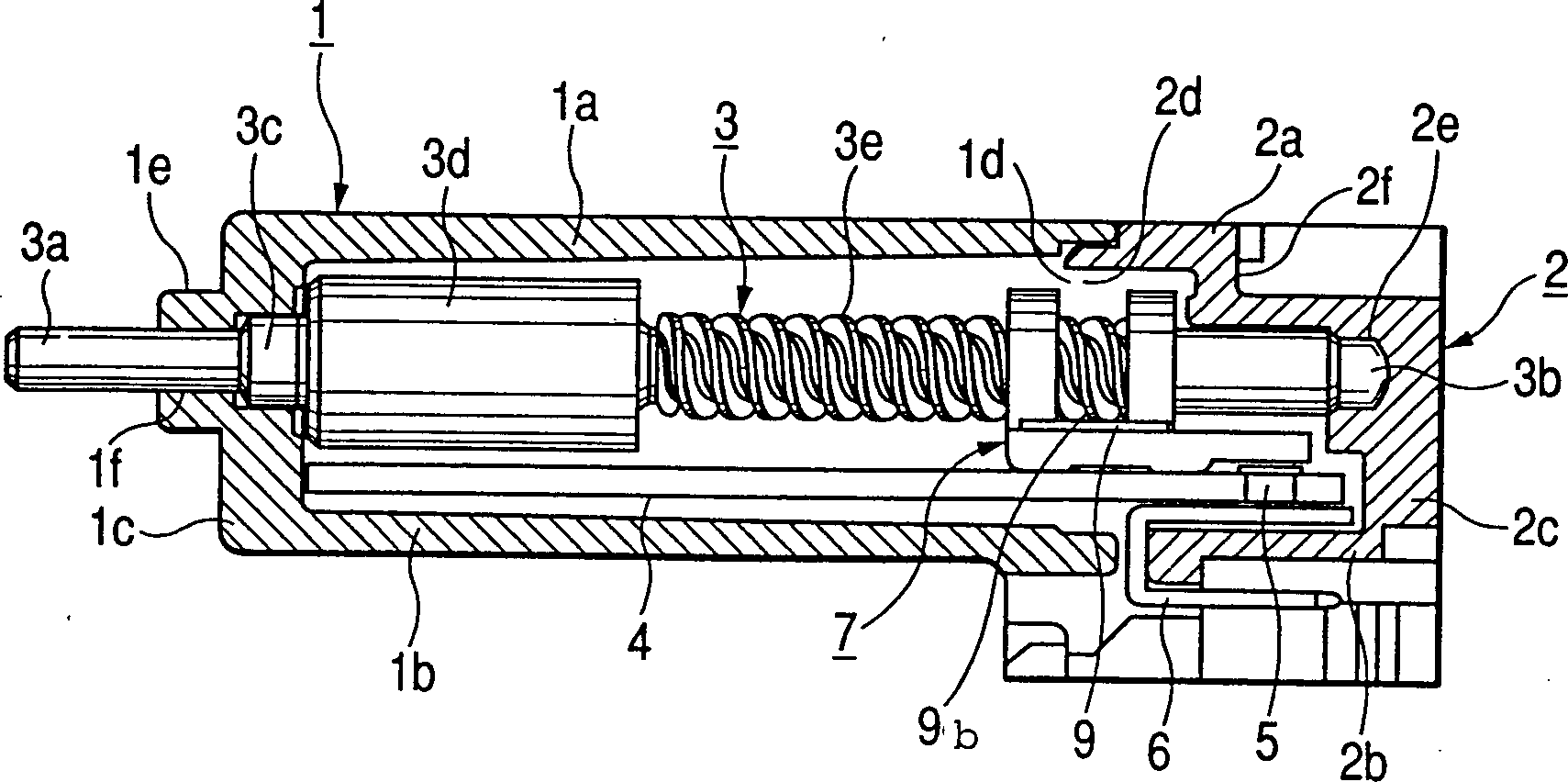
1 eine
Schnittansicht eines rotationsmäßig betätigbaren
elektrischen Bauteils gemäß einem ersten
Ausführungsbeispiel
der vorliegenden Erfindung; 1 a sectional view of a rotationally actuatable electrical component according to a first embodiment of the present invention;
2 eine
Frontansicht unter Darstellung eines beweglichen Blocks mit einem
daran angebrachten Gleitstück,
wie er bei dem elektrischen Bauteil des ersten Ausführungsbeispiels
verwendet wird; 2 a front view showing a movable block with an attached slider, as used in the electrical component of the first embodiment;
3 eine
Draufsicht auf die Darstellung der 2; 3 a plan view of the representation of 2 ;
4 eine
Seitenansicht der Darstellung der 2; 4 a side view of the illustration of the 2 ;
5 eine
Draufsicht auf eine plattenförmige
Feder, die bei dem elektrischen Bauteil des ersten Ausführungsbeispiels
verwendet wird; 5 a plan view of a plate-shaped spring, which is used in the electrical component of the first embodiment;
6 eine
Seitenansicht der Darstellung der 5; 6 a side view of the illustration of the 5 ;
7 eine
Draufsicht auf eine plattenförmige
Feder, die bei einem rotationsmäßig betätigbaren elektrischen
Bauteil gemäß einem
zweiten Ausführungsbeispiel
der vorliegenden Erfindung verwendet wird; 7 a plan view of a plate-shaped spring, the rotationally actuatable electrical component according to a second embodiment Example of the present invention is used;
8 eine
Draufsicht auf eine plattenförmige
Feder, die bei einem rotationsmäßig betätigbaren elektrischen
Bauteil gemäß einem
dritten Ausführungsbeispiel
der vorliegenden Erfindung verwendet wird; 8th a plan view of a plate-shaped spring, which is used in a rotationally actuatable electrical component according to a third embodiment of the present invention;
9 eine
Frontansicht eines herkömmlichen
rotationsmäßig betätigbaren,
elektrischen Bauteils; und 9 a front view of a conventional rotationally actuatable electrical component; and
10 eine
auseinandergezogene Perspektivansicht unter Darstellung eines beweglichen
Bereichs bei dem herkömmlichen
elektrischen Bauteil. 10 an exploded perspective view showing a movable area in the conventional electrical component.
Im folgenden werden rotationsmäßig angetriebene
bzw. betätigbare
elektrische Bauteile, die die vorliegende Erfindung verkörpern, unter
Bezugnahme auf die Begleitzeichnungen erläutert.The following are driven in rotation
or actuatable
electrical components embodying the present invention
Reference to the accompanying drawings explained.
Bei dem rotationsmäßig betätigbaren
elektrischen Bauteil gemäß dem ersten
Ausführungsbeispiel,
wie es in den 1 bis 6 dargestellt ist, ist ein erstes
Gehäuseelement 1 durch
Formen aus einem isolierenden, formbaren Material gebildet und besitzt eine
obere Wand 1a sowie eine untere Wand 1b, die einander
gegenüberliegend
angeordnet sind, eine Seitenwand 1c, die eine Verbindung
zwischen der oberen und der unteren Wand 1a, 1b herstellt
und sich in Querrichtung bzw. quer zu der oberen und unteren Wand
erstreckt, ein Paar einander gegenüberliegender Seitenwände (nicht
gezeigt), die sich in Längsrichtung
erstrecken, sowie einen der Seitenwand 1c gegenüberliegenden
offenen Teil 1d. Die Seitenwand 1c ist mit einem
nach außen
ragenden konvexen Bereich 1e und einer Öffnung if mit kreisförmigem Querschnitt
ausgebildet, wobei die Öffnung if
durch den konvexen Bereich 1e hindurch ausgebildet ist
und einen Öffnungsbereich
mit kleinem Durchmesser sowie einen Öffnungsbereich mit mittlerem Durchmesser
aufweist.In the case of the rotatable electrical component according to the first exemplary embodiment, as shown in FIGS 1 to 6 is shown is a first housing element 1 formed by molding from an insulating, moldable material and has an upper wall 1a as well as a lower wall 1b , which are arranged opposite to each other, a side wall 1c that connect between the top and bottom walls 1a . 1b and extends transversely to the top and bottom walls, a pair of opposed side walls (not shown) that extend longitudinally, and one of the side wall 1c opposite open part 1d , The side wall 1c is with an outwardly convex area 1e and an opening if formed with a circular cross section, the opening if through the convex region 1e is formed therethrough and has an opening area with a small diameter and an opening area with a medium diameter.
Ein zweites Gehäuseelement 2 ist durch
Formen aus einem isolierenden, formbaren Material gebildet und besitzt
eine obere Wand 2a mit einem Stufenbereich 2f,
eine der oberen Wand 2a gegenüberliegende untere Wand 2b,
eine Seitenwand 2c, die eine Verbindung zwischen der oberen
und der unteren Wand 2a, 2b herstellt, ein Paar
einander gegenüberliegender
Seitenwände
(nicht gezeigt) sowie einen der Seitenwand 2c gegenüberliegenden
offenen Teil 2d. Eine Öffnung 2e mit
kreisförmigem
Querschnitt ist in der Innenseite der Seitenwand 2c ausgebildet.
Das erste und das zweite Gehäuseelement 1, 2 sind
derart angeordnet, daß die
jeweiligen offenen Teile 1d und 2d miteinander
in Ver bindung stehen. In diesem Zustand sind das erste und das zweite
Gehäuseelement
durch ein geeignetes Verfahren, wie z.B. ein Einschnappverfahren,
miteinander gekoppelt, um auf diese Weise ein einziges Gehäuse zu bilden,
das im wesentlichen hermetisch abgeschlossen ist.A second housing element 2 is formed by molding from an insulating, moldable material and has an upper wall 2a with a step range 2f , one of the top wall 2a opposite bottom wall 2 B , a side wall 2c that connect between the top and bottom walls 2a . 2 B produces a pair of opposing side walls (not shown) and one of the side wall 2c opposite open part 2d , An opening 2e with a circular cross-section is in the inside of the side wall 2c educated. The first and the second housing element 1 . 2 are arranged so that the respective open parts 1d and 2d communicate with each other. In this state, the first and second housing members are coupled together by a suitable method, such as a snap-in method, to form a single housing that is substantially hermetically sealed.
Eine Antriebswelle 3 ist
z.B. durch zerspanende Bearbeitung eines Metallmaterials in eine
im wesentlichen stangenförmige
Gestalt gebildet und besitzt zylindrische Bereiche 3a und 3b mit
kleinem Durchmesser, die an den beiden Enden der Welle ausgebildet
sind, einen zylindrischen Bereich 3c mit mittlerem Durchmesser,
der sich an den einen Bereich 3a mit kleinem Durchmesser
anschließt
und einen etwas größeren Durchmesser
als dieser aufweist, einen zylindrischen Bereich 3d mit
großem Durchmesser,
der sich an den Bereich 3c mit mittlerem Durchmesser anschließt und einen
etwas größeren Durchmesser
aufweist, sowie einen Gewindebereich 3e, der sich an den
Bereich 3d mit großem Durchmesser
anschließt.
Der Gewindebereich 3e schließt sich an den anderen Bereich 3b mit
kleinem Durchmesser an. Der eine Bereich 3a mit kleinem Durchmesser
und der Bereich 3c mit mittlerem Durchmesser der Antriebswelle 3 sind
derart ausgebildet, daß sie
sich durch die in dem konvexen Bereich 1e des ersten Gehäuseelements 1 ausgebildete Öffnung 2f hindurcherstrecken,
wobei die Spitze des Bereichs 3a mit kleinem Durchmesser
von der Seitenwand 1c nach außen ragt, während die Spitze des anderen
Bereichs 3b mit kleinem Durchmesser in der in der Seitenwand 2c des
zweiten Gehäuseelements 2 ausgebildeten Öffnung 2e festgehalten
ist. Der Bereich 3d mit großem Durchmesser und der Gewindebereich 3e sind
im Inneren des ersten und des zweiten Gehäuseelements 1, 2 aufgenommen. Auf
diese Weise ist die Antriebswelle 3 durch die beiden Gehäuseelemente
drehbar gehalten.A drive shaft 3 is formed, for example, by machining a metal material into a substantially rod-like shape and has cylindrical areas 3a and 3b with a small diameter, which are formed at the two ends of the shaft, a cylindrical portion 3c with a medium diameter that extends to one area 3a connects with a small diameter and has a slightly larger diameter than this, a cylindrical region 3d with a large diameter that adjusts to the area 3c connects with a medium diameter and has a slightly larger diameter, and a threaded area 3e that is related to the area 3d with a large diameter. The thread area 3e joins the other area 3b with a small diameter. One area 3a small diameter and the area 3c with medium diameter of the drive shaft 3 are designed so that they are in the convex area 1e of the first housing element 1 trained opening 2f extend through, the top of the area 3a with a small diameter from the side wall 1c protrudes outward while the top of the other area 3b with a small diameter in the in the side wall 2c of the second housing element 2 trained opening 2e is captured. The area 3d with large diameter and the thread area 3e are inside the first and second housing members 1 . 2 added. In this way the drive shaft 3 held rotatably by the two housing elements.
Ein isolierendes Substrat 4 ist
in Form einer ebenen Platte unter Verwendung eines isolierenden Formmaterials
gebildet, und eine Mehrzahl elektrisch leitfähiger Strukturen ist auf einer
oberen Oberfläche des
isolierenden Substrats 4 durch Aufdrucken eines Widerstands-Farbmaterials
oder dergleichen gebildet, wobei dies jedoch in der Zeichnung nicht
dargestellt ist. An Endbereichen der elektrisch leitfähigen Strukturen
sind ösenartige
Kontakteinrichtungen 5 in Anlage an den elektrisch leitfähigen Strukturen
angeordnet. In diesem Zusammenhang ist eine Mehrzahl U-förmiger Anschlüsse 6,
die ösenartige
Kontakteinrichtungen 5 aufweisen, mit der Unterseite des
isolierenden Substrats 4 durch die Kontakteinrichtungen 5 vernietet
sowie daran befestigt.An insulating substrate 4 is formed in the form of a flat plate using an insulating molding material, and a plurality of electrically conductive structures are on an upper surface of the insulating substrate 4 by printing a resistive color material or the like, but this is not shown in the drawing. At the end areas of the electrically conductive structures are eye-like contact devices 5 arranged in contact with the electrically conductive structures. In this connection there is a plurality of U-shaped connections 6 who have favourited Eyelet-type Contacts 5 have, with the underside of the insulating substrate 4 through the contact devices 5 riveted and attached to it.
Das isolierende Substrat 4 ist
durch Nuten geführt
und gehalten, die in zwei Seitenwänden (nicht gezeigt) des Gehäuseelements 1 ausgebildet
sind. In diesem Zustand sind die U-förmigen Anschlüsse 6 von
dem offenen Teil 2d des zweiten Gerhäuseelements 2 nach
außen
auf die Außenseite
dieses Gehäuseelements
geführt,
wobei ihre Spitzen entlang des äußeren Wandbereichs
der unteren Wand 2b des zweiten Gehäuseelements 2 in Richtung
auf die Seitenwand 2c des zweiten Gehäuseelements 2 ragen.
Die Spitzen bzw. freien Enden der Anschlüsse 6 bilden steckerartige
Verbinderbereiche.The insulating substrate 4 is guided and held by grooves in two side walls (not shown) of the housing element 1 are trained. The U-shaped connections are in this state 6 from the open part 2d of the second housing element 2 led outwards to the outside of this housing element, with their tips along the outer wall area of the lower wall 2 B of the second housing element 2 towards the side wall 2c of the second housing element 2 protrude. The tips or free ends of the connections 6 form connector-like connector areas.
Ein beweglicher Block 7,
wie er in den 2 bis 4 dargestellt ist, ist durch
Formen eines isolierenden Kunstharzmaterials gebildet und besitzt
einen allgemein rechteckigen Substratbereich 7a sowie ein Paar
paralleler Haltebereiche 7e, die einander gegenüberliegend
angeordnet sind und von dem Substratbereich 7a nach oben
ragen.A moving block 7 as he in the 2 to 4 is formed by molding an insulating resin material and has one generally rectangular substrate area 7a and a pair of parallel holding areas 7e which are arranged opposite to each other and from the substrate region 7a protrude upwards.
Der Substratbereich 7a besitzt
eine rechteckige Öffnung 7b,
die sich in einem nahezu zentralen Teil befindet, so wie einen rechteckigen
Aussparungsbereich 7c, der an dem einen Ende des Substratbereichs
ausgebildet ist. Die Haltebereiche 7e sind jeweils mit
einer kreisförmigen Öffnung 7d ausgebildet, die
eine zu der Oberfläche
des Substratbereichs 7a parallele Achse besitzen.The substrate area 7a has a rectangular opening 7b which is located in an almost central part, such as a rectangular recess area 7c , which is formed at one end of the substrate region. The stopping areas 7e are each with a circular opening 7d formed one to the surface of the substrate region 7a have parallel axis.
Die beiden Haltebereiche 7e sind
beidseits der rechteckigen Öffnung 7b einander
gegenüber
angeordnet. An der unteren Oberfläche des Substratbereichs 7a ist
ein zylindrischer konvexer Bereich (nicht gezeigt) ausgebildet,
und an beiden Seiten der unteren Oberfläche sind Vorsprünge bzw.
Ausbauchungen 7f ausgebildet.The two stopping areas 7e are on both sides of the rectangular opening 7b arranged opposite each other. On the lower surface of the substrate area 7a a cylindrical convex portion (not shown) is formed, and protrusions are formed on both sides of the lower surface 7f educated.
Der Gewindebereich 3e der
Antriebswelle 3 ist durch die Öffnungen 7d der beiden
Haltebereiche 7e hindurchgeführt, so daß sich der bewegliche Block 7 in
derartigem Eingriff mit der Antriebswelle 3 befindet, daß er in
Axialrichtung der Antriebswelle beweglich ist.The thread area 3e the drive shaft 3 is through the openings 7d of the two stopping areas 7e passed so that the movable block 7 in such engagement with the drive shaft 3 is that it is movable in the axial direction of the drive shaft.
Ein Schleifer 8 ist durch
Stanzen und Biegen einer Elastizität aufweisenden Metallplatte,
wie z.B. einer Platte aus Phosphorbronze, gebildet und besitzt eine
Mehrzahl allgemein halbkreisförmiger
Kontaktbereiche 8a, die an dem einen Ende des Gleitstücks ausgebildet
sind, sowie einen Haltebereich 8b, der an dem gegenüberliegenden
Ende des Schleifers vorgesehen ist, um die Kontaktbereiche 8a zu
halten. Eine kreisförmige Öffnung (nicht
gezeigt) ist nahezu in der Mitte des Haltebereichs 8b ausgebildet.
Diese Öffnung
des Haltebereichs 8b ist auf den an der Unterseite des
Substratbereichs 7a des beweglichen Blocks 7 ausgebildeten
konvexen Bereich gepaßt,
wonach ein VerA grinder 8th is formed by stamping and bending an elastic metal plate, such as a phosphor bronze plate, and has a plurality of generally semicircular contact areas 8a , which are formed at one end of the slider, and a holding area 8b , which is provided at the opposite end of the grinder, around the contact areas 8a to keep. A circular opening (not shown) is almost in the middle of the holding area 8b educated. This opening of the holding area 8b is on the bottom of the substrate area 7a of the moving block 7 trained convex area, after which a Ver
stemm- bzw. Vernietvorgang folgt,
wodurch dem Schleifer 8 an dem beweglichen Block 7 festgelegt
ist. In diesem festgelegten Zustand befinden sich die Kontaktbereiche 8a des
Schleifers 8 ist Positionen gegenüber äer in dem Substratbereich 7a des beweglichen
Blocks 7 ausgebildeten Öffnung
7b. Wenn
die Kontaktbereiche 8a verlagert und nach oben gedrückt werden,
sind sie in der Öffnung 7b positioniert.Caulking or riveting follows, causing the grinder 8th on the moving block 7 is set. The contact areas are in this defined state 8a the grinder 8th is positions opposite to each other in the substrate area 7a of the moving block 7 trained opening 7b , If the contact areas 8a moved and pushed upwards, they are in the opening 7b positioned.
Eine plattenförmige Feder 9, wie
sie in den 5 und 6 gezeigt ist, ist durch
Stanzen und Biegen einer Elastizität aufweisenden Metallplatte,
wie z.B. einer Platte aus Phosphorbronze, allgemein doppel-T-förmig bzw.
I-förmig
ausgebildet und besitzt einen Haltebereich 9a, einen nach
oben ragenden, halbkugelförmigen
Vorsprung 9b, der im wesentlichen im Zentrum des Haltebereichs 9a ausgebildet ist,
sowie nach innen ragende halbkreisförmige Festhaltebereiche 9c,
die jeweils an den vier Enden der allgemeinen I-Form ausgebildet
sind. Die plattenförmige
Feder 9 ist derart ausgebildet, daß sie insgesamt bogenförmig gewölbt ist,
wobei der Vorsprung 9b an dem Scheitel der bogenförmigen Gestalt
ausgebildet ist. Die plattenförmige
Feder 9 wird mit ihrem Vorsprung 9b an der oberen
Oberflächenseite
auf dem Substratbereich 7a des beweglichen Blocks 7 angeordnet,
so daß sie
die Öffnung 7b des
Substratbereichs überdeckt.
Dabei werden die Festhaltebereiche 9c der plattenförmigen Feder 9 derart
festgehalten, daß sie
sich in die Seitenwände
der Festhaltebereiche 7e hineindrücken. In diesem festgehaltenen
Zustand ist der nach oben ragende Vorsprung 9b über der Öffnung 7b des
Substratbereichs 7a positioniert.A plate-shaped spring 9 as in the 5 and 6 is shown, is formed by punching and bending an elastic metal plate, such as a plate made of phosphor bronze, generally double T-shaped or I-shaped and has a holding area 9a , a protruding hemispherical projection 9b which is essentially at the center of the holding area 9a is formed, and inwardly projecting semicircular holding areas 9c each formed at the four ends of the general I-shape. The plate-shaped spring 9 is designed such that it is arched as a whole, the projection 9b is formed on the apex of the arcuate shape. The plate-shaped spring 9 with their head start 9b on the upper surface side on the substrate area 7a of the moving block 7 arranged so that they have the opening 7b of the substrate area covered. The holding areas 9c the plate-shaped spring 9 held in such a way that they fit into the side walls of the holding areas 7e Push. In this state, the upward projection is 9b over the opening 7b of the substrate area 7a positioned.
Die Herstellung für die plattenförmige Feder 9 ist
einfach, da es sich bei ihr im allgemeinen um eine flache Plattenform
handelt, wie dies bereits erwähnt
wurde.The manufacture for the plate-shaped spring 9 is simple since it is generally a flat plate shape, as mentioned earlier.
Der bewegliche Block 7,
an dem das Gleitstück 8 und
die plattenförmige
Feder 9 in der vorstehend beschriebenen Weise verriegelt
sind, ist in Axialrichtung der Antriebswelle 3 hin- und
herbeweglich, wenn der Gewindebereich 3b der Antriebswelle
in die Öffnungen 7d eingeführt ist,
die jeweils in den beiden Haltebereichen 7e des beweglichen Blocks 7 ausgebildet
sind. In diesem Zustand ist die mit dem beweglichen Block 7 in
Eingriff befindliche plattenförmige Feder 9 zwischen
dem beweglichen Block und der Antriebswelle 3 angeordnet;
und ihr Vorsprung 9b befindet sich in elastischem Eingriff
mit einem Gewindefußbereich
bzw. Gewindeerhebungsbereich des Gewindebereichs 3e, während die
Vorsprünge 7f an dem
isolierenden Substrat 4 anliegen, um eine Rotationsbewegung
des beweglichen Blocks 7 um die Antriebswelle 3 zu
verhindern. Aufgrund der Vorsprünge 7f kommen
nur die Kontaktbereiche 8a des Schleifers 8 in
elastischen Kontakt mit den elektrisch leitfähigen Strukturen (nicht gezeigt)
auf dem isolierenden Substrat 4.The moving block 7 on which the slider 8th and the plate-shaped spring 9 are locked in the manner described above, is in the axial direction of the drive shaft 3 back and forth when the thread area 3b the drive shaft into the openings 7d is introduced, each in the two holding areas 7e of the moving block 7 are trained. In this state it is the one with the movable block 7 engaged plate-shaped spring 9 between the movable block and the drive shaft 3 arranged; and their lead 9b is in elastic engagement with a thread foot area or thread elevation area of the thread area 3e while the ledges 7f on the insulating substrate 4 apply to a rotational movement of the movable block 7 around the drive shaft 3 to prevent. Because of the ledges 7f come only the contact areas 8a the grinder 8th in elastic contact with the electrically conductive structures (not shown) on the insulating substrate 4 ,
Im nachfolgenden wird die Montage
des rotationsmäßig betätigbaren
elektrischen Bauteils mit der vorstehend beschriebenen Ausbildung
erläutert.The following is the assembly
of the rotatable
electrical component with the training described above
explained.
Zuerst wird das isolierende Substrat 4,
an dem elektrisch leitfähige
Strukturen und Anschlüsse 6 ausgebildet
sind, in die Führungsnuten
eingepaßt, die
in den Seitenwänden
(nicht gezeigt) des ersten Gehäuseelements 1 ausgebildet
sind. Als nächstes wird
Schleifer 8 an der unteren Oberfläche des Substratbereichs 7a des
beweglichen Blocks 7 befestigt, und die plattenförmige Feder 9 wird
auf der oberen Oberfläche
des Substratbereichs 7a derart plaziert, daß ihr Vorsprung 9b nach
oben ragt, und die plattenförmige
Feder 9 wird mit den Haltebereichen 7e in Eingriff
gebracht. Danach wird der Gewindebereich 3e der Antriebswelle 3 in
die in den Haltebereichen 7e des beweglichen Blocks 7 ausgebildeten Öffnungen 7d eingeführt. Die
Antriebswelle 3 ist somit in dem beweglichen Block 7 montiert.
Zu diesem Zeitpunkt befindet sich der durch den beweglichen Block 7 festgehaltene
Vorsprung 9b der plattenförmigen Feder 9 in
Eingriff mit einem Gewindefußbereich
des Gewindebereichs 3e.First, the insulating substrate 4 , on the electrically conductive structures and connections 6 are formed, fitted in the guide grooves, which in the side walls (not shown) of the first housing element 1 are trained. Next is grinder 8th on the lower surface of the substrate area 7a of the moving block 7 attached, and the plate-shaped spring 9 is on the top surface of the substrate area 7a placed in such a way that their lead 9b protrudes upwards, and the plate-shaped spring 9 comes with the holding areas 7e engaged. Then the thread area 3e the drive shaft 3 in the in the holding areas 7e of the moving block 7 trained openings 7d introduced. The drive shaft 3 is thus in the moving block 7 assembled. At this point in time it is through the moving block 7 fixed lead 9b the plate-shaped spring 9 in engagement with a threaded foot portion of the threaded region 3e ,
Wenn die Antriebswelle 3 in
den beweglichen Block 7 eingeführt ist, werden als nächstes die Bereiche 3a, 3c mit
kleinem und mittlerem Durchmesser der Antriebswelle ist die Öffnung 1f eingeführt, die
in der Seitenwand 1c des ersten Gehäuseelements 1 ausgebildet
ist. Dabei wird die Spitze des Bereichs 3a mit kleinem
Durchmesser der Antriebswelle 3 von der Seitenwand 1c nach
außen
ragend angeordnet.If the drive shaft 3 in the moving block 7 the next are the areas 3a . 3c with a small and medium diameter of the drive shaft is the opening 1f introduced that in the side wall 1c of the first housing element 1 is trained. The top of the range 3a with a small diameter of the drive shaft 3 from the side wall 1c arranged protruding outwards.
In diesem Zustand sind die an dem
beweglichen Block 7 festgelegten Kontaktbereiche 8a des Schleifer 8 in
elastischer Berührung
mit den elektrisch leitfähigen
Strukturen angeordnet, die auf dem isolierenden Substrat 4 ausgebildet
sind.In this state they are on the movable block 7 defined contact areas 8a of the grinder 8th arranged in elastic contact with the electrically conductive structures on the insulating substrate 4 are trained.
Danach wird der zweite, offene Teil 2d des zweiten
Gehäuseelements 2 in überlappender
Beziehung mit dem offenen Teil 1d des ersten Gehäuseelements 1 angeordnet,
wodurch beide Gehäuseelemente
miteinander in Eingriff gebracht werden sowie einstöckig miteinander
ausgebildet werden. Gleichzeitig ist der Bereich 3b mit
kleinem Durchmesser der Antriebswelle 3 in der in der Seitenwand 2c des
zweiten Gehäuseelements 2 ausgebildeten Öffnung 2e festgehalten.
Ferner liegt die untere Wand 2b des zweiten Gehäuseelements 2 den
U-förmigen
Anschlüssen 6 gegenüber, woäurch das
isolierende Substrat 4 mit den daran befestigten Anschlüssen 6 in
dem Gehäuse
festgelegt ist.After that, the second, open part 2d of the second housing element 2 in an overlapping relationship with the open part 1d of the first housing element 1 arranged, whereby both housing elements are brought into engagement with one another and are formed in one piece with one another. At the same time, the area 3b with a small diameter of the drive shaft 3 in the in the side wall 2c of the second housing element 2 trained opening 2e recorded. The lower wall is also located 2 B of the second housing element 2 the U-shaped connections 6 opposite, through which the insulating substrate 4 with the connectors attached to it 6 is set in the housing.
Dabei sind die Spitzen bzw. freien
Enden der Anschlüsse 6 außerhalb
des Gehäuses
angeordnet. Die Montage des rotationsmäßig betätigbaren elektrischen Bauteils
ist damit abgeschlossen.The tips or free ends of the connections 6 arranged outside the housing. The assembly of the electrical component which can be actuated in terms of rotation is thus completed.
Es folgt nun eine Beschreibung der
Arbeitsweise. dieses elektrischen Bauteils.There now follows a description of the
Operation. of this electrical component.
Wenn der Bereich 3a mit
kleinem Durchmesser der Antriebswelle 3 , der aus der in
der Seitenwand 1c des ersten Gehäuseelements 1 ausgebildeten Öffnung 1f herausragt,
z.B. im Uhrzeigersinn verdreht wird, dreht sich der Gewindebereich 3e der
Antriebswelle 3 ebenfalls in derselben Richtung. Bei dieser
Rotationsbewegung des Gewindebereichs 3e im Uhrzeigersinn
wird der Vorsprung 9b der plattenförmigen Feder 9, der
sich in Eingriff mit einem Gewindefußbereich des Gewindebereichs 34 befindet,
in Axialrichtung (in 1 nach
links) der Antriebswelle 3 bewegt, mit dem Ergebnis, daß der bewegliche Block 7 zusammen
mit der damit verriegelten plattenförmigen Feder 9 in
Axialrichtung der Antriebswelle 3 bewegt wird und die Kontaktbereiche 8a des
an dem beweglichen Block 7 befestigten Schleifers 8 auf
den elektrisch leitfähigen
Strukturen, die auf dem isolierenden Substrat 4 ausgebildet
sind, eine Gleitbewegung ausführen.
Bei dieser Gleitbewegung der Kontaktbereiche 8a auf den
elektrisch leitfähigen
Strukturen wird beispielsweise der Widerstandswert, der von den
Anschlüssen 6 abgegeben
wird, erhöht
(oder reduziert).If the area 3a with a small diameter of the drive shaft 3 that from the in the side wall 1c of the first housing element 1 trained opening 1f protrudes, e.g. if it is turned clockwise, the thread area turns 3e the drive shaft 3 also in the same direction. During this rotational movement of the thread area 3e clockwise is the lead 9b the plate-shaped spring 9 that engages with a threaded foot portion of the threaded portion 34 located in the axial direction (in 1 to the left) of the drive shaft 3 moved, with the result that the movable block 7 together with the plate-shaped spring locked with it 9 in the axial direction of the drive shaft 3 is moved and the contact areas 8a of the moving block 7 attached grinder 8th on the electrically conductive structures on the insulating substrate 4 are trained to perform a sliding movement. With this sliding movement of the contact areas 8a on the electrically conductive structures, for example, the resistance value is that of the connections 6 delivered, increased (or reduced).
Bei weiteregehender Rotationsbewegung des
Bereichs 3a mit kleinem Durchmesser im Uhrzeigersinn wird
der bewegliche Block 7 weiter in Axialrichtung (in 1 nach links) bewegt und
wird schließlich
in Anlage an dem Bereich 3d mit großem Durchmesser der Antriebswelle 3 gebracht,
wodurch eine weitere Bewegung des beweglichen Blocks ver- hindert
wird. In diesem Anlagezustand des beweglichen Blocks 7 an
dem Bereich 3d mit großem
Durchmesser wird im Fall einer Rotationsbewegung des Bereichs 3a mit
kleinem Durchmesser im Uhrzeigersinn der Vorsprung 9b der
mit dem beweglichen Block 7 verriegelten plattenförmigen Feder 9 derart betätigt, daß er sich über Gewindespitzen
des Gewindebereichs 3e hinwegbewegt, wodurch sich der Bereich 3a mit
kleinem Durchmesser ohne Bewegung des beweglichen Blocks drehen
kann. Bei der Bewegung über
die Gewinde spitzen des Gewindebereichs 3e wird der Vorsprung 9b der
plattenförmigen Feder 9 entgegen
der Federkraft der plattenförmigen Feder
nach unten gedrückt
und dadurch innerhalb der Öffnung 7b des
beweglichen Blocks 7 positioniert. Nach dem Überwinden
der Gewindespitzen kommt der Vorsprung 9b wiederum in Eingriff
mit Gewindefußbereichen
des Gewindebereichs 3e.As the area continues to rotate 3a with a small diameter clockwise the moving block 7 further in the axial direction (in 1 to the left) and eventually attaches to the area 3d with large diameter of the drive shaft 3 brought, which prevents further movement of the movable block. In this condition of the movable block 7 on the area 3d with a large diameter in the case of a rotational movement of the area 3a with a small diameter clockwise the projection 9b the one with the moving block 7 locked plate-shaped spring 9 actuated such that it extends over thread tips of the thread area 3e moved away, causing the area to move 3a can rotate with a small diameter without moving the movable block. When moving over the threads, tip the thread area 3e becomes the lead 9b the plate-shaped spring 9 pressed against the spring force of the plate-shaped spring and thereby within the opening 7b of the moving block 7 positioned. After overcoming the thread tips, the protrusion comes 9b again in engagement with threaded foot areas of the threaded area 3e ,
Die Öffnung 7b des beweglichen
Blocks 7 ist somit derart ausgebildet, daß sie die
nach unten gehende Bewegung des Vorsprungs 9b der plattenförmigen Feder 9 nicht
behindert.The opening 7b of the moving block 7 is thus designed to prevent the downward movement of the projection 9b the plate-shaped spring 9 not disabled.
Bei dem vorliegenden Ausführungsbeispiel handelt
es sich bei dem Gewindebereich 3e um eine zweigängige Konstruktion,
so daß bei
einer Drehung des Bereichs 3a mit kleinem Durchmesser der
Antriebswelle 3 um höchstens
eine halbe Umdrehung im Uhrzeigersinn der bewegliche Block 7 mit
den Gewindeeinrichtungen in Eingriff gelangt und bei einer weitergehenden
Rotationsbewegung des Bereichs 3a mit kleinem Durchmesser
der bewegliche Block 7 in der zu der vorstehend angegebenen
Richtung entgegengesetzten Richtung bewegt wird, nämlich in Axialrichtung
nach rechts in 1, wonach
schließlich
die Haltebereiche 7e des beweglichen Blocks 7 an
dem Stufenbereich 2f der oberen Wand 2a des zweiten
Gehäuseelements 2 in
Anlage gelangen, so daß sich
der bewegliche Block nicht weiter bewegen läßt. Bei einer weitergehenden
Rotationsbewegung des Bereichs 3a mit kleinem Durchmesser
der Antriebswelle 3 wird in derselben Weise, wie dies zuvor beschrieben
wurde, der Vorsprung 9b der plattenförmigen Feder 9 derart
bewegt, daß er
sich über
Gewindespitzen des Gewindebereichs 3e der Antriebswelle 3 hinwegbewegt,
so daß der
bewegliche Block 7 unbeweglich gehalten wird.In the present exemplary embodiment, the thread area is concerned 3e around a two-flight construction, so that when the range rotates 3a with a small diameter of the drive shaft 3 the movable block by a maximum of half a turn clockwise 7 comes into engagement with the threaded devices and with a further rotational movement of the area 3a with small diameter the moving block 7 is moved in the opposite direction to the above direction, namely in the axial direction to the right in 1 , after which the stopping areas 7e of the moving block 7 at the step area 2f the top wall 2a of the second housing element 2 come into contact so that the moving block cannot be moved any further. If the area continues to rotate 3a with a small diameter of the drive shaft 3 becomes the protrusion in the same manner as previously described 9b the plate-shaped spring 9 so that it moves over thread tips of the thread area 3e the drive shaft 3 moved away so that the moving block 7 is held immobile.
Selbst wenn der Bereich 3a mit
kleinem Durchmesser der Antriebswelle 3 über den
Betätigungsbereich
des beweg- 1ichen
Blocks 7 hinaus rotationsmäßig bewegt wird, besteht somit
keine Gefahr, daß das
rotationsmäßig betätigbare
elektrische Bauteil gemäß dem vorliegenden
Ausführungsbeispiel
durch eine übermäßige Rotationsbewegung
der Antriebswelle 3 zerbricht, da sich der Vorsprung 9b der
mit dem beweglichen Block 7 in Eingriff befindlichen, plattenförmigen Feder 9 in
vertikaler Richtung bewegt, um sich über die Gewindespitzen des
Gewindebereichs 3e hinwegzubewegen.Even if the area 3a with a small diameter of the drive shaft 3 over the operating range of the movable block 7 is also rotated, there is no risk that the rotationally actuatable electrical component according to the present embodiment by an excessive rotational movement of the drive shaft 3 breaks up because of the lead 9b the one with the moving block 7 engaged chen, plate-shaped spring 9 moved in the vertical direction to over the thread tips of the thread area 3e away move.
Durch Verändern des dimensionsmäßigen Verhältnisses
zwischen dem Bereich 3d mit großem Durchmesser und dem Gewindebereich 3e ist
es ferner möglich,
unterschiedlichen Hubbewegungsstrecken Rechnung zu tragen.By changing the dimensional relationship between the area 3d with large diameter and the thread area 3e it is also possible to take into account different stroke movements.
Es wird nun auf eine plattenförmige Feder Bezug
genommen, die bei einem rotationsmäßig betätigbaren elektrischen Bauteil
gemäß dem zweiten Ausführungsbeispiel
der vorliegenden Erfindung verwendet wird, wie dies in 7 in einer Draufsicht dargestellt
ist.Reference is now made to a plate-shaped spring which is used in a rotationally actuatable electrical component according to the second exemplary embodiment of the present invention, as shown in FIG 7 is shown in a plan view.
In dem nachfolgend genannten Punkt
unterscheidet sich die Konstruktion der plattenförmigen Feder bei diesem zweiten
Ausführungsbeispiel
von der der plattenförmigen
Feder bei dem vorausgehenden ersten Ausführungsbeispiel. Die bei dem
ersten Ausführungsbeispiel
verwendete plattenförmige
Feder 9 ist insgesamt im allgemeinen doppel-T-förmig, und
die halbkreisförmigen
Festhaltebereiche (insgesamt vier) sind jeweils an den vier Enden
der Doppel-T-Form ausgebildet, während
bei der plattenförmigen
Feder 10, wie sie bei diesem zweiten Ausführungsbeispiel
verwendet wird, die beiden auf der rechten Seite der plattenförmigen Feder 9 des
ersten Ausführungsbeispiels
angeordneten Festhaltebereiche 9c weggelassen sind.In the following point, the construction of the plate-shaped spring in this second embodiment differs from that of the plate-shaped spring in the previous first embodiment. The plate-shaped spring used in the first embodiment 9 is generally double T-shaped, and the semicircular retention areas (four in total) are each formed at the four ends of the double T-shape, while the plate-shaped spring 10 , as used in this second embodiment, the two on the right side of the plate-shaped spring 9 of the first embodiment arranged holding areas 9c are omitted.
Die plattenförmige Feder 10 wird
durch Stanzen und Biegen einer Elastizität aufweisenden Metallplatte,
wie z.B. einer Platte aus Phosphorbronze, allgemein U-förmig ausgebildet
und besitzt einen Haltebereich 10a, einen halbkugelförmigen Vorsprung 10b,
der im wesentlichen im Zentrum des Haltebereichs 10a ausgebildet
ist, sowie halbkreisförmige
Festhaltebereiche 10c, die an Enden des Haltebereichs ausgebildet
sind und in Richtung nach innen ragen. Die plattenförmige Feder 10 ist
insgesamt bogenförmig
gekrümmt
ausgebildet, wobei sich der Vorsprung 10b an dem Scheitel
der Bogenform befindet.The plate-shaped spring 10 is generally formed into a U-shape by punching and bending an elastic metal plate, such as a plate made of phosphor bronze, and has a holding area 10a , a hemispherical projection 10b which is essentially at the center of the holding area 10a is formed, and semicircular retention areas 10c which are formed at ends of the holding area and protrude inward. The plate-shaped spring 10 is curved in the shape of an arc, the projection 10b located at the apex of the arch shape.
Die plattenförmige Feder 10 wird
auf dem Substratbereich 7a derart angeordnet, daß der Haltebereich 10a die
in dem Substratbereich 7a des beweglichen Blocks 7 ausgebildete Öffnung 7b überdeckt
und daß seine
Festhaltebereiche 10b sich in eine Seitenwand von einem
der Haltebereiche 7e hineindrücken.The plate-shaped spring 10 is on the substrate area 7a arranged such that the holding area 10a those in the substrate area 7a of the moving block 7 trained opening 7b covered and that its holding areas 10b into a side wall from one of the holding areas 7e Push.
Als nächstes folgt eine Beschreibung
einer plattenförmigen
Feder, die bei einem rotationsmäßig betätigbaren
elektrischen Bauteil gemäß dem dritten Ausführungsbeispiel
der vorliegenden Erfindung verwendet wird, wobei dies in 8 in einer Draufsicht dargestellt
ist.Next, a description will be given of a plate-shaped spring used in a rotary electric component according to the third embodiment of the present invention, which is shown in FIG 8th is shown in a plan view.
Die Konstruktion der bei diesem dritten
Ausführungsbeispiel
verwendeten plattenförmigen
Feder unterscheidet sich von der der bei dem ersten Ausführungsbeispiel
verwendeten plattenförmigen
Feder in dem nachfolgend genannten Punkt. Die plattenförmige Feder 9 bei
dem ersten Ausführungsbeispiel
ist insgesamt allgemein doppel-T-förmig, und die halbkreisförmigen Festhaltebereiche 9c (insgesamt
vier) sind jeweils an den vier Enden der Doppel-T-Form ausgebildet,
wogegen die bei dem vorliegenden dritten Ausführungsbeispiel verwendete plattenförmige Feder 11 allgemein
S-förmig ausgebildet
ist und halbkreisförmige
Festhaltebe reiche (insgesamt zwei) jeweils an einem der beiden Endbereiche
der S-Form ausgebildet sind.The construction of the plate-shaped spring used in this third embodiment differs from that of the plate-shaped spring used in the first embodiment in the following point. The plate-shaped spring 9 in the first embodiment is generally double T-shaped, and the semicircular retention areas 9c (a total of four) are respectively formed at the four ends of the double-T shape, whereas the plate-shaped spring used in the present third embodiment 11 is generally S-shaped and semicircular areas Festhaltbe (a total of two) are each formed on one of the two end regions of the S-shape.
Die plattenförmige Feder 11 ist
durch Stanzen und Biegen einer Elastizität aufweisenden Metallplatte,
wie z.B. einer Platte aus Phosphorbronze, gebildet und besitzt einen
Haltebereich 11a, einen halbkugelförmigen Vorsprung 11b,
der im wesentlichen im Zentrum des Haltebereichs 11a ausgebildet ist,
sowie halbkreisförmige
Festhaltebereiche 11c, die in Bezug auf den Vorsprung 11b an
punktsymetrischen Positionen ausgebildet sind und nach innen ragen.
Die plattenförmige
Feder 11 ist insgesamt bogenförmig gekrümmt ausgebildet, wobei sich
der Vorsprung 11b an dem Scheitel der Bogenform befindet.The plate-shaped spring 11 is formed by stamping and bending an elastic metal plate, such as a plate made of phosphor bronze, and has a holding area 11a , a hemispherical projection 11b which is essentially at the center of the holding area 11a is formed, and semicircular retention areas 11c that in terms of the lead 11b are formed at point-symmetrical positions and protrude inwards. The plate-shaped spring 11 is curved in the shape of an arc, the projection 11b located at the apex of the arch shape.
Der bei jedem der vorstehend erläuterten Ausführungsbeispiele
verwendete bewegliche Block 7 besitzt zwar ein Paar paralleler
Haltebereiche 7e, die einander gegenüberliegend angeordnet sind,
jedoch stellt dies keine Einschränkung
dar. Der bewegliche Block 7 kann auch nur mit einem solchen
Haltebereich ausgebildet sein.The movable block used in each of the above-described embodiments 7 has a pair of parallel holding areas 7e , which are arranged opposite to each other, but this is not a limitation. The movable block 7 can also be formed only with such a holding area.
Wie vorstehend erläutert wurde,
besitzt das rotationsmäßig betätigbare
elektrische Bauteil gemäß der vorliegenden
Erfindung eine Gehäuseeinrichtung,
eine Antriebswelle, die von der Gehäuseeinrichtung gehalten ist
und einen Gewindebereich aufweist, ein isolierendes Substrat, das
von der Gehäuseeinrichtung
gehalten ist und elektrisch leitfähige Strukturen aufweist, ein
Schleifer, der mit den elektrisch leitfähigen Strukturen in Gleitkontakt
tritt, einen beweglichen Block, der den Schleifer hält, sowie
eine plattenförmige
Feder, die zwischen dem beweglichen Block und der Antriebswelle
angeordnet ist und mit dem beweglichen Block gekoppelt bzw. verriegelt
ist, wobei die plattenförmige
Feder einen nach Art einer Erhebung ausgebildeten Vorsprung aufweist,
wobei der Vorsprung der plat tenförmigen Feder
mit dem Gewindebereich der Antriebswelle in elastische Berührung gebracht
ist, so daß sich
der bewegliche Block bei einer Rotationsbewegung der Antriebswelle
bewegt. Da die plattenförmige
Feder zwischen dem beweglichen Block und der Antriebswelle angeordnet
ist, läßt sich
somit der Vorgang zum Verriegeln der plattenförmigen Feder mit dem beweglichen
Block einfach sowie unabhängig
von der Anordnung der Antriebswelle ausführen.As explained above
has the rotationally operable
electrical component according to the present
Invention a housing device
a drive shaft which is held by the housing device
and has a threaded portion, an insulating substrate that
from the housing device
is held and has electrically conductive structures
Grinder in sliding contact with the electrically conductive structures
occurs, a movable block that holds the grinder, and
a plate-shaped
Spring between the movable block and the drive shaft
is arranged and coupled or locked to the movable block
is, the plate-shaped
Spring has a projection designed in the manner of an elevation,
the projection of the plat-shaped spring
brought into elastic contact with the threaded area of the drive shaft
is so that
the movable block when the drive shaft rotates
emotional. Since the plate-shaped
Spring arranged between the movable block and the drive shaft
is, can
thus the process of locking the plate-shaped spring with the movable
Block simple as well as independent
from the arrangement of the drive shaft.
Bei dem rotationsmäßig betätigbaren
elektrischen Bauteil gemäß der vorliegenden
Erfindung kann der bewegliche Block mit einem einzigen Haltebereich
versehen sein, wobei in dem Haltebereich eine Öffnung zum Einführen der
Antriebswelle ausgebildet ist und die Antriebswelle in diese Öffnung eingeführt ist.
Der bewegliche Block und die Antriebswelle lassen sich somit in
integraler Weise miteinander ausbilden, und diese integrale Kombination
aus beweglichem Block und Antriebswelle läßt sich in einfacher Weise
in die Gehäuseeinrichtung
integrieren.In the rotationally actuatable electrical component according to the present invention, the movable block can be provided with a single holding area, an opening for introducing the drive shaft being formed in the holding area and the drive shaft being inserted into this opening. The moving block and the drive Shafts can thus be formed in an integral manner with one another, and this integral combination of a movable block and drive shaft can be easily integrated into the housing device.
Bei dem rotationsmäßig betätigbaren
elektrischen Bauteil gemäß der vorliegenden
Erfindung kann der bewegliche Block auch mit einem Paar einander
gegenüberliegender
Haltebereiche versehen sein, wobei in den beiden Haltebereichen Öffnungen zum
Einführen
der Antriebswelle ausgebildet sind und die Antriebswelle in diese Öffnungen
eingesetzt ist. Auf diese Weise läßt sich der bewegliche Block
in stabiler Weise an der Antriebswelle anbringen, und er kann in
stabiler Weise durch die Antriebswelle bewegt werden.With the rotatable
electrical component according to the present
The movable block can also be invented with a pair of each other
opposed
Be holding areas provided, openings in the two holding areas
Introduce
the drive shaft are formed and the drive shaft in these openings
is used. In this way, the movable block can be
attach to the drive shaft in a stable manner and it can be in
be moved in a stable manner by the drive shaft.
Bei dem rotationsmäßig betätigbaren
elektrischen Bauteil gemäß der vorliegenden
Erfindung ist die plattenförmige
Feder durch einen Haltebereich des beweglichen Blocks festgehalten,
und somit wird der Haltebereich, der die Antriebswelle und den beweglichen
Block in integraler Weise miteinander vereinigt, auch zum Festhalten
der plat tenförmigen
Feder verwendet. Somit reduziert sich die Anzahl der verwendeten
Teile.With the rotatable
electrical component according to the present
Invention is the plate-shaped
Spring held by a holding area of the movable block,
and thus the holding area that the drive shaft and the movable
Block integrated in an integral manner, also for holding on
the plate-shaped
Spring used. This reduces the number of used
Parts.
Bei dem rotationsmäßig betätigbaren
elektrischen Bauteil gemäß der vorliegenden
Erfindung ist eine Öffnung
in dem beweglichen Block ausgebildet, und der Vorsprung der plattenförmigen Feder
sowie Kontaktbereiche des Gleitstücks befinden sich an der Öffnung gegenüberliegenden
Stellen. Selbst wenn der Vorsprung der plattenförmigen Feder und die Kontaktbereiche
des Gleitstücks
durch ihre jeweilige Elastizität
gebogen werden und sich in Richtung auf die Öffnung bewegen, können beide
innerhalb der Öffnung
angeordnet werden, so daß es
nicht erforderlich ist, irgendeinen zusätzlichen Raum proportional
zu dem Ausmaß einer
derartigen Bewegung vorzusehen, wodurch eine Größenreduzierung des elektrischen
Bauteils ermöglicht
ist.With the rotatable
electrical component according to the present
Invention is an opening
formed in the movable block, and the projection of the plate-shaped spring
and contact areas of the slider are located opposite the opening
Put. Even if the projection of the plate-shaped spring and the contact areas
of the slider
through their respective elasticity
both can be bent and move towards the opening
inside the opening
be arranged so that it
no additional proportional space is required
to the extent of a
to provide such movement, thereby reducing the size of the electrical
Component
is.