DE19850552B4 - Actuation for an axially effective clutch pressure plate and disengagement unit for a vehicle clutch - Google Patents
Actuation for an axially effective clutch pressure plate and disengagement unit for a vehicle clutch Download PDFInfo
- Publication number
- DE19850552B4 DE19850552B4 DE19850552A DE19850552A DE19850552B4 DE 19850552 B4 DE19850552 B4 DE 19850552B4 DE 19850552 A DE19850552 A DE 19850552A DE 19850552 A DE19850552 A DE 19850552A DE 19850552 B4 DE19850552 B4 DE 19850552B4
- Authority
- DE
- Germany
- Prior art keywords
- force
- pressure plate
- spring
- unit according
- plunger
- Prior art date
- Legal status (The legal status is an assumption and is not a legal conclusion. Google has not performed a legal analysis and makes no representation as to the accuracy of the status listed.)
- Expired - Fee Related
Links
Classifications
-
- F—MECHANICAL ENGINEERING; LIGHTING; HEATING; WEAPONS; BLASTING
- F16—ENGINEERING ELEMENTS AND UNITS; GENERAL MEASURES FOR PRODUCING AND MAINTAINING EFFECTIVE FUNCTIONING OF MACHINES OR INSTALLATIONS; THERMAL INSULATION IN GENERAL
- F16D—COUPLINGS FOR TRANSMITTING ROTATION; CLUTCHES; BRAKES
- F16D13/00—Friction clutches
- F16D13/58—Details
- F16D13/583—Diaphragm-springs, e.g. Belleville
- F16D13/585—Arrangements or details relating to the mounting or support of the diaphragm on the clutch on the clutch cover or the pressure plate
-
- F—MECHANICAL ENGINEERING; LIGHTING; HEATING; WEAPONS; BLASTING
- F16—ENGINEERING ELEMENTS AND UNITS; GENERAL MEASURES FOR PRODUCING AND MAINTAINING EFFECTIVE FUNCTIONING OF MACHINES OR INSTALLATIONS; THERMAL INSULATION IN GENERAL
- F16D—COUPLINGS FOR TRANSMITTING ROTATION; CLUTCHES; BRAKES
- F16D25/00—Fluid-actuated clutches
- F16D25/08—Fluid-actuated clutches with fluid-actuated member not rotating with a clutching member
- F16D25/082—Fluid-actuated clutches with fluid-actuated member not rotating with a clutching member the line of action of the fluid-actuated members co-inciding with the axis of rotation
- F16D25/087—Fluid-actuated clutches with fluid-actuated member not rotating with a clutching member the line of action of the fluid-actuated members co-inciding with the axis of rotation the clutch being actuated by the fluid-actuated member via a diaphragm spring or an equivalent array of levers
-
- F—MECHANICAL ENGINEERING; LIGHTING; HEATING; WEAPONS; BLASTING
- F16—ENGINEERING ELEMENTS AND UNITS; GENERAL MEASURES FOR PRODUCING AND MAINTAINING EFFECTIVE FUNCTIONING OF MACHINES OR INSTALLATIONS; THERMAL INSULATION IN GENERAL
- F16D—COUPLINGS FOR TRANSMITTING ROTATION; CLUTCHES; BRAKES
- F16D25/00—Fluid-actuated clutches
- F16D25/08—Fluid-actuated clutches with fluid-actuated member not rotating with a clutching member
- F16D25/082—Fluid-actuated clutches with fluid-actuated member not rotating with a clutching member the line of action of the fluid-actuated members co-inciding with the axis of rotation
- F16D25/083—Actuators therefor
Landscapes
- Engineering & Computer Science (AREA)
- General Engineering & Computer Science (AREA)
- Mechanical Engineering (AREA)
- Mechanical Operated Clutches (AREA)
Abstract
Betätigung für eine axial wirksame Kupplungsdruckplatte (1) mit Mitteln (2) zum Aufbringen einer axial gerichteten Kraft auf die Druckplatte (3), dadurch gekennzeichnet, daß die Mittel (2) zum Aufbringen der axial gerichteten Kraft radial von einer Kraft mit einer radialen Komponente angetrieben wird, und die Betätigung einen Kraftwandler (2) aufweist, der eine Kraft mit einer radialen Komponente in eine axial gerichtete Kraft wandeln kann und der Kraftwandler (2) einen Winkelhebel (2) mit einem axial gerichteten Hebelarm und mit einem radial gerichteten Hebelarm umfaßt.Actuation for an axially acting clutch pressure plate (1) with means (2) for applying an axially directed force to the pressure plate (3), characterized in that the means (2) for applying the axially directed force radially from a force with a radial component is driven, and the actuator comprises a force transducer (2) which can convert a force with a radial component into an axially directed force and the force transducer (2) comprises an angle lever (2) with an axially directed lever arm and with a radially directed lever arm ,
Description
Die Erfindung betrifft eine Betätigung für eine axial wirksame Kupplungsdruckplatte mit Mitteln zum Aufbringen einer im Wesentlichen axial gerichteten Kraft auf die Druckplatte sowie eine Ausrückeeinheit für eine Fahrzeugkupplung mit einer auf eine Druckplatte wirkenden Tellerfeder und mit einem mit der Tellerfeder wirkverbundenen Zentralausrücker.The The invention relates to an actuation for an axial effective clutch pressure plate with means for applying an im Essentially axially directed force on the pressure plate as well as a Release unit for a vehicle clutch with a plate spring acting on a pressure plate and with a with the diaphragm spring operatively connected Zentralausrücker.
Derartige
Ausrückeeinheiten
für Kupplungsdruckplatten
umfassen in der Regel eine zwischen der Kupplungsdruckplatte und
einem Kupplungsgehäuse
verspannte Tellerfeder, welche die Kupplungsdruckplatte gegen eine
Reibscheibe einer Kupplung presst, und sind beispielsweise in de
Wegen
der hierbei vorhandenen Hebellängen
der Zungen weisen derartige Kupplungen verhältnismäßig große Baulängen auf. Zu dieser durch die
Hebel bedingten Baulänge
kommt noch hinzu, dass durch einen Belagverschleiß die Tellerfeder eine
Winkelbewegung ausführt,
die ebenfalls durch die Baulänge
der Kupplung vorgehalten werden muss. Darüber hinaus weist die Gesamtordnung
der Kupplung Toleranzen zwischen Kupplungsgehäuse und Zentralausrücker auf,
die ebenfalls über
die Baulänge
aufgefangen werden müssen.
Auch die Kupplungen aus der
Es ist Aufgabe vorliegender Erfindung, eine möglichst schmale Bauweise einer entsprechenden Kupplung zu ermöglichen.It Object of the present invention, the smallest possible construction of a allow appropriate coupling.
Als erste Lösung schlägt die Erfindung eine Betätigung für eine axial wirksame Kupplungsdruckplatte mit den Merkmalen des Anspruchs 1 vor.When first solution beats the invention an actuation for one axially effective clutch pressure plate with the features of the claim 1 ago.
Dadurch, dass die Mittel zum Aufbringen der im Wesentlichen axial gerichteten Kraft einen radialen Antrieb umfassen, erfolgt dementsprechend eine radiale Verlagerung der Anordnung, wenn ein derartiger Antrieb erfolgt. Insofern braucht bei der erfindungsgemäßen Anordnung eine axiale Baulänge für diesen Antrieb nicht bereitgestellt zu werden. Es wird darüber hinaus auch dementsprechend weniger Bauraum in axialer Richtung für eine Verschleißnachstellung benötigt. Insbesondere lassen sich auch große Hebel an der Tellerfeder vermeiden, die ebenso zu einer großen Baulänge beitragen.Thereby, in that the means for applying the substantially axially directed Force include a radial drive, is accordingly a radial Displacement of the assembly when such a drive is made. In this respect, in the inventive arrangement needs an axial length for this Drive not to be provided. It gets beyond that also correspondingly less space in the axial direction for a wear adjustment needed. In particular, it is also possible to use large levers on the diaphragm spring avoid, which also contribute to a great length.
Die Erfindung kann bspw. dadurch umgesetzt werden, dass die Druckplattenbetätigung einen Kraftwandler und einen Kraftgeber umfasst. Hierbei ist der Kraftwandler derart ausgestaltet, dass er eine Kraft mit einer radialen Komponente in eine im Wesentlichen axial gerichtete, auf die Druckplatte aufgebracht Kraft wandeln kann.The For example, the invention can be implemented by the pressure plate actuation being a force transducer and a force transmitter. Here, the force transducer is like this designed to have a force with a radial component in it a substantially axially directed, applied to the printing plate Can transform power.
Insbesondere kann der Kraftwandler Bestandteil der Mittel zum Aufbringen der im Wesentlichen axial gerichteten Kraft sein und bspw. einen Winkelhebel mit einem im Wesentlichen axial gerichteten Hebelarm und mit einem im Wesentlichen radial gerichteten Hebelarm umfassen. Hierdurch wird eine besonders einfache konstruktive Ausgestaltung des Kraftwandlers sowie eine nur minimale Änderung der an sich bekannten und bewährten Anordnung nach dem Stand der Technik bedingt, bei welchen der bekannte, axial zu betätigende Hebelarm lediglich durch einen erfindungsgemäßen Winkelhebel ersetzt werden braucht.Especially The force transducer can be part of the means of applying the be substantially axially directed force and, for example, an angle lever with a substantially axially directed lever arm and with a comprise substantially radially directed lever arm. hereby is a particularly simple structural design of the force transducer as well as a minimal change the well-known and proven Arrangement according to the prior art, in which the known, axially actuated Lever be replaced only by an angle lever according to the invention needs.
Der Kraftgeber realisiert hierbei den radialen Antrieb der Mittel zum Aufbringen der im Wesentlichen axial gerichteten Kraft und ist dementsprechend derart ausgestaltet, dass er mit einer Kraft, die eine radiale Komponente aufweist, auf den Kraftwandler wirken kann.Of the Force transmitter realized here the radial drive of the means for Applying the substantially axially directed force and is accordingly so He designed that with a force that is a radial component can act on the force transducer.
Der Kraftgeber kann einen im Wesentlichen axial angeordneten Stößel umfassen, der durch einen Zentralausrücker betätigbar ist. Dieses ermöglicht einen verhältnismäßig einfachen konstruktiven Aufbau des Kraftgebers.Of the Force transmitter may comprise a substantially axially disposed plunger, by a Zentralausrücker actuated is. This allows a relatively simple one constructive structure of the force transmitter.
In der Regel sind derartige Kupplungsdruckplatten bzw. derartige Kupplungen im Wesentlichen radialsymmetrisch ausgestaltet. Dementsprechend ist es vorteilhaft, wenn auch die Mittel zum Aufbringen der im Wesentlichen axial gerichteten Kraft bzw. der Kraftwandler sowie der Kraftgeber eine entsprechende Symmetrie aufweisen. So kann beispielsweise der Kraftwandler eine Tellerfeder sein, die einen im Wesentlichen radial gerichteten Bereich aufweist, welcher auf die Druckplatte in bekannter Weise eine axial gerichtete Kraft ausübt, und die axial abgewinkelte Bereiche aufweist, durch die ein erfindungsgemäßer im Wesentlichen radialsymmetrischer Winkelhebel realisiert wird. Ebenso kann der Stößel radialsymmetrisch, beispielsweise als Tellerfeder, ausgebildet sein und sich beim Betätigen radial ausdehnen.In As a rule, such clutch pressure plates or such couplings designed substantially radially symmetrical. Accordingly is it is advantageous, although the means for applying the substantially axially directed force or the force transducer and the force transmitter have a corresponding symmetry. For example, the Force transducer will be a diaphragm spring, which is a substantially radial directed area, which on the pressure plate in known Way exerts an axially directed force, and the axially angled Having areas through which an inventive substantially radially symmetrical Angle lever is realized. Likewise, the plunger may be radially symmetrical, for example as a plate spring, be formed and when pressed radially expand.
Dementsprechend schlägt die Erfindung eine Ausrückeeinheit für eine Fahrzeugkupplung mit einer auf diene Druckplatte wirkenden Tellerfeder und mit einem mit der Tellerfeder wirkverbundenen Zentralausrücker vor, bei welchem die Tellerfeder einen in Axialrichtung abgebogenen Bereich aufweist, an welchem ein durch den Zentralausrücker radial betätigbarer Stößel angreift.Accordingly beats the invention is a disengagement unit for one Vehicle clutch with an acting on diene pressure plate plate spring and with a Zentralerrücker operatively connected to the plate spring, in which the plate spring has a bent region in the axial direction at which a radially actuated by the Zentralausrücker Pestle attacks.
Wie bereits vorstehend angedeutet, kann zwischen der Tellerfeder mit dem in Axialrichtung abgebogenen Bereich und dem Zentralausrücker eine im Wesentlichen radial wirksame Tellerfeder vorgesehen sein. Diese wirkt als Stößel, indem sie radial auf den in Axialrichtung abgebogenen Bereich der auf die Druckplatte wirkenden Tellerfeder wirkt. Insofern dient diese im Wesentlichen radial wirksame Tellerfeder in diesem Falle als Stößel.As already indicated above, can with between the plate spring the axially bent portion and the Zentralausrücker a in Essentially provided radially effective disc spring. These acts as a ram by they radially on the bent in the axial direction of the area the pressure plate acting disc spring acts. In this respect, this serves essentially radially effective disc spring in this case as Pestle.
Der Zentralausrücker kann einen konischen Bereich aufweisen, an dem der Stößel zumindest im belasteten Zustand anliegt. Diese Anordnung ermöglicht eine radiale Auslenkung, da der Zentralausrücker, wie auch nach dem Stand der Technik bekannt, in axialer Richtung zum Betätigen der Ausrückeeinheit bewegt wird. Hierdurch wird der konische Bereich entsprechend verlagert. Diese Anordnung ermöglicht des Weiteren ein Nachstellen des Stößels, wenn die Kupplung einem Verschleiß unterliegt.Of the CSC may have a conical area, where the plunger at least in the loaded state. This arrangement allows a radial deflection, as the Zentralausrücker, as well as the state known in the art, in the axial direction for actuating the disengaging unit is moved. As a result, the conical region is shifted accordingly. This arrangement allows Furthermore, an adjustment of the plunger when the clutch a Wear is subject.
Radialen Asymmetrien des Stößels bzw. bei dem Kraftgeben kann ein Zentralausrücker oder ein ähnlicher Antrieb für Ausrückeeinheit bzw. die Kupplungsdruckplatten dadurch begegnen, dass zwischen dem Zentralausrücker bzw. dem Antrieb und dem Stößel bzw. dem Kraftgeber eine Baugruppe, die beispielsweise den konischen Bereich umfasst, mit einem radialen Spiel vorgesehen ist. Eine derartige Baugruppe ist auch unabhängig von den übrigen Merkmalen vorteilhaft, solange ein Stößel bzw. ein Kraftgeber durch einen Zentralausrücker bzw. einen Antrieb betätigt werden soll.radial Asymmetries of the plunger or in the power giving can a Zentralausrücker or a similar Drive for disengaging unit or the clutch pressure plates thereby encounter that between the CSC or the drive and the plunger or the power transmitter, an assembly, for example, the conical Area includes, with a radial clearance is provided. Such an assembly is also independent from the other features advantageous as long as a plunger or a force transmitter can be actuated by a Zentralausrücker or a drive should.
Die Ausrückeeinheit kann einen Nachsteller umfassen, der auf den Zentralausrücker zumindest im entlasteten Zustand der Ausrückeeinheit eine Kraft ausübt, so dass der Stößel einer durch Verschleiß bedingten Verlagerung der Tellerfeder folgen kann. Eine derartige Verlagerung folgt aus der Tatsache, dass bei einem Verschleiß die Kupplungsdruckplatte näher an eine Mitnehmerscheibe heranrückt, wodurch die Tellerfeder verla gert wird. Eine derartige Verlagerung ist in der Regel einer Ausrückebewegung der Tellerfeder entgegengerichtet.The disengaging unit may include a Nachsteller on the Zentralausrücker at least in Relieved state of the release unit exerting a force so that the ram of a due to wear Displacement of the diaphragm spring can follow. Such a shift follows from the fact that when worn the clutch pressure plate closer to a driving disk zooming, whereby the diaphragm spring is verla siege. Such a shift is in the rule of a disengagement movement the diaphragm spring directed counter.
Um einer derartigen Verlagerung folgen zu können, benötigt der Stößel somit etwas Raum. Diesen Raum kann der Nachsteller dadurch schaffen, dass er eine Kraft, insbesondere eine axiale Kraft, auf den Zentralausrücker ausübt und diesen auf diese Weise ein wenig von dem Stößel abhebt. Diesen auf diese Weise geschaffenen Raum kann der Stößel nutzen, um einer verschleißbedingten Verlagerung zu folgen.Around To be able to follow such a shift, the plunger thus requires some space. this Space can create the adjuster by having a power, in particular, an axial force on the Zentralausrücker exerts and this in this way a little bit off the ram. This on this The space created by the plunger can be used in a wear-related manner Relocation to follow.
Ausrückeeinheit und Nachsteller können elastisch miteinander verbunden sein. Hierdurch kann das Verhältnis zwischen der durch den Nachsteller auf den Zentralausrücker aufgebrachten Kraft und der verschleißbedingten Verlagerung in geeigneter Weise in Abhängigkeit gesetzt werden.disengaging unit and adjusters can be elastic be connected to each other. This allows the ratio between the force applied to the central release by the adjuster the wear-related Relocation can be set in a suitable manner.
Einerseits kann diese elastische Verbindung im Bereich der Tellerfeder vorgesehen sein. Sollte die hierbei durch den Nachsteller aufgebrachte Kraft nicht ausreichend sein, können zwischen dem Nachsteller und dem Stößel weitere bzw. andere elastische Elemente vorgesehen sein, die entsprechende Kraftverhältnisse bedingen.On the one hand can this elastic connection provided in the region of the plate spring be. Should not the force applied by the adjuster can be sufficient between the adjuster and the plunger further or other elastic Elements be provided, the corresponding power relations require.
Der Nachsteller kann beispielsweise mit dem Stößel in der Nähe der Tellerfeder verbunden sein und an einem konischen Nachstellbereich des Zentralbereichs anliegen, wobei der konische Nachstellbereich stumpfer ausgebildet ist, als der konische Gereicht des Zentralausrückers. Auf diese Weise ist die durch den Nachrücker ausgeübte axiale Kraft etwas stärker als die durch den Stößel auf den Zentralausrücker ausgeübte Kraft und es wird eine leichte axiale Verschiebung des Zentralausrückers gewährleistet.Of the Adjuster can, for example, with the plunger in the vicinity of the plate spring be connected and at a conical adjustment of the central area abut, wherein the conical adjustment formed dull is, as the conical ranks of the central release. That way is the through the follower practiced axial force slightly stronger than through the pestle the central release practiced Force and it is ensured a slight axial displacement of the Zentralausrückers.
Diese leichte Verschiebung reicht aus, dass der Stößel einer verschleißbedingten Verlagerung der Tellerfeder folgen kann.These slight shift is sufficient that the plunger of a wear-related Displacement of the diaphragm spring can follow.
Andererseits kann der Nachtsteller auch unmittelbar an dem konischen Bereich anliegen.on the other hand The nightstand can also be directly at the conical area issue.
Weitere Vorteile, Ziele und Eigenschaften vorliegender Erfindung werden anhand der Beschreibung vorliegender Zeichnungen verdeutlicht, in welcher beispielhaft eine Betätigung für eine axial wirksame Kupplungsdruckplatte bzw. eine Ausrückeeinheit für eine Fahrzeugkupplung dargestellt sind. In der Zeichnung zeigen:Further Advantages, objects and characteristics of the present invention illustrated by the description of the present drawings, in which exemplifies an operation for one axially effective clutch pressure plate or a disengagement unit for one Vehicle coupling are shown. In the drawing show:
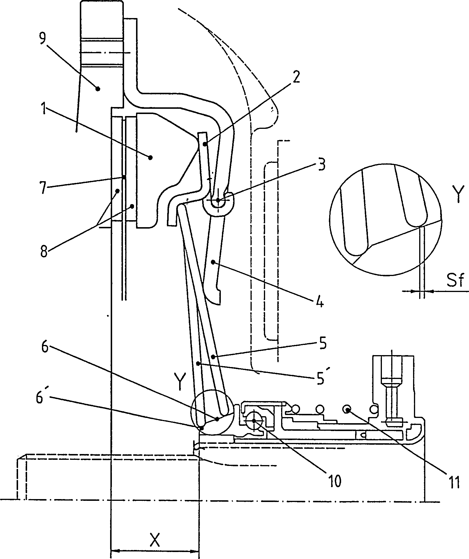
Zum
Auskuppeln wird die Tellerfeder
Die
Tellerfeder
Beim
Einkuppeln verspannt sich die Tellerfeder
Hierdurch wird erreicht, dass die kräftemäßigen und geometrischen Verhältnisse dieser Anordnung trotz Verschleiß der Kupplung nahezu unverändert bleiben.hereby is achieved that the vigorous and geometric relationships this arrangement remain virtually unchanged despite wear of the clutch.
Die
in den Figuren dargestellten Ausführungsbeispiele unterscheiden
sich durch die konkrete Ausgestaltung der Tellerfedern
Bei
dem in den
Das
in
Auch
die in
Bei
dieser Ausführungsform
ist der konische Bereich
Das Ausrücklager kann an Stelle einer hydraulischen Verstellung auch über einen Hebel angetrieben werden.The release bearing can in place of a hydraulic adjustment via a Levers are driven.
Wie
in
Claims (14)
Priority Applications (5)
| Application Number | Priority Date | Filing Date | Title |
|---|---|---|---|
| DE19850552A DE19850552B4 (en) | 1998-04-17 | 1998-11-03 | Actuation for an axially effective clutch pressure plate and disengagement unit for a vehicle clutch |
| DE59909831T DE59909831D1 (en) | 1998-04-17 | 1999-03-24 | Actuation for an axially effective clutch pressure plate and corresponding release unit |
| EP99105922A EP0950826B1 (en) | 1998-04-17 | 1999-03-24 | Actuator for an axially movable clutch pressure plate, and release assembly incorporating same |
| JP10848699A JP4311508B2 (en) | 1998-04-17 | 1999-04-15 | Actuator for clutch pressure plate acting in the axial direction and release unit for vehicle clutch |
| US09/293,710 US6152276A (en) | 1998-04-17 | 1999-04-16 | Actuation mechanism for a clutch pressure plate with axial effect and disengagement unit for a motor vehicle clutch |
Applications Claiming Priority (5)
| Application Number | Priority Date | Filing Date | Title |
|---|---|---|---|
| DE19817171.4 | 1998-04-17 | ||
| DE19817171 | 1998-04-17 | ||
| DE19817838.7 | 1998-04-22 | ||
| DE19817838 | 1998-04-22 | ||
| DE19850552A DE19850552B4 (en) | 1998-04-17 | 1998-11-03 | Actuation for an axially effective clutch pressure plate and disengagement unit for a vehicle clutch |
Publications (2)
| Publication Number | Publication Date |
|---|---|
| DE19850552A1 DE19850552A1 (en) | 1999-10-21 |
| DE19850552B4 true DE19850552B4 (en) | 2009-09-24 |
Family
ID=26045570
Family Applications (2)
| Application Number | Title | Priority Date | Filing Date |
|---|---|---|---|
| DE19850552A Expired - Fee Related DE19850552B4 (en) | 1998-04-17 | 1998-11-03 | Actuation for an axially effective clutch pressure plate and disengagement unit for a vehicle clutch |
| DE59909831T Expired - Lifetime DE59909831D1 (en) | 1998-04-17 | 1999-03-24 | Actuation for an axially effective clutch pressure plate and corresponding release unit |
Family Applications After (1)
| Application Number | Title | Priority Date | Filing Date |
|---|---|---|---|
| DE59909831T Expired - Lifetime DE59909831D1 (en) | 1998-04-17 | 1999-03-24 | Actuation for an axially effective clutch pressure plate and corresponding release unit |
Country Status (1)
| Country | Link |
|---|---|
| DE (2) | DE19850552B4 (en) |
Cited By (1)
| Publication number | Priority date | Publication date | Assignee | Title |
|---|---|---|---|---|
| DE102014216098A1 (en) * | 2014-08-13 | 2016-02-18 | Schaeffler Technologies AG & Co. KG | Actuator arrangement with radial intermediate pressure piece and actuating element displaceable intermediate component |
Families Citing this family (2)
| Publication number | Priority date | Publication date | Assignee | Title |
|---|---|---|---|---|
| FR2834024B1 (en) * | 2001-12-20 | 2004-01-30 | Valeo | CLUTCH MECHANISM, ESPECIALLY FOR A MOTOR VEHICLE |
| JP5278260B2 (en) * | 2009-09-08 | 2013-09-04 | アイシン精機株式会社 | Clutch device |
Citations (6)
| Publication number | Priority date | Publication date | Assignee | Title |
|---|---|---|---|---|
| DE161908C (en) * | ||||
| US2406238A (en) * | 1941-12-08 | 1946-08-20 | Atwood Vacuum Machine Co | Two-way clutch |
| US2682942A (en) * | 1947-07-23 | 1954-07-06 | Greyhound Corp | Clutch mechanism |
| DE4128880A1 (en) * | 1990-09-27 | 1992-04-02 | Valeo | Clutch assembly for motor vehicle - is mounted support flange with cover attached to flywheel, supporting pressure plate actuator |
| DE4243170A1 (en) * | 1992-12-19 | 1994-06-23 | Daimler Benz Ag | Disengagement drive for vehicle clutch |
| DE19613763C1 (en) * | 1996-04-06 | 1997-05-07 | Ortlinghaus Werke Gmbh | Friction brake or friction clutch |
-
1998
- 1998-11-03 DE DE19850552A patent/DE19850552B4/en not_active Expired - Fee Related
-
1999
- 1999-03-24 DE DE59909831T patent/DE59909831D1/en not_active Expired - Lifetime
Patent Citations (6)
| Publication number | Priority date | Publication date | Assignee | Title |
|---|---|---|---|---|
| DE161908C (en) * | ||||
| US2406238A (en) * | 1941-12-08 | 1946-08-20 | Atwood Vacuum Machine Co | Two-way clutch |
| US2682942A (en) * | 1947-07-23 | 1954-07-06 | Greyhound Corp | Clutch mechanism |
| DE4128880A1 (en) * | 1990-09-27 | 1992-04-02 | Valeo | Clutch assembly for motor vehicle - is mounted support flange with cover attached to flywheel, supporting pressure plate actuator |
| DE4243170A1 (en) * | 1992-12-19 | 1994-06-23 | Daimler Benz Ag | Disengagement drive for vehicle clutch |
| DE19613763C1 (en) * | 1996-04-06 | 1997-05-07 | Ortlinghaus Werke Gmbh | Friction brake or friction clutch |
Cited By (2)
| Publication number | Priority date | Publication date | Assignee | Title |
|---|---|---|---|---|
| DE102014216098A1 (en) * | 2014-08-13 | 2016-02-18 | Schaeffler Technologies AG & Co. KG | Actuator arrangement with radial intermediate pressure piece and actuating element displaceable intermediate component |
| DE102014216098B4 (en) * | 2014-08-13 | 2016-03-24 | Schaeffler Technologies AG & Co. KG | Actuator arrangement with radial intermediate pressure piece and actuating element displaceable intermediate component |
Also Published As
| Publication number | Publication date |
|---|---|
| DE19850552A1 (en) | 1999-10-21 |
| DE59909831D1 (en) | 2004-08-05 |
Similar Documents
| Publication | Publication Date | Title |
|---|---|---|
| DE102022133281B4 (en) | clutch with preloaded actuating device | |
| DE69722166T2 (en) | CLUTCH MECHANISM FOR A FRICTION CLUTCH WITH REDUCED SOLVENT EFFORT | |
| WO2010020208A1 (en) | Dual clutch | |
| DE4405344B4 (en) | friction clutch | |
| DE19850552B4 (en) | Actuation for an axially effective clutch pressure plate and disengagement unit for a vehicle clutch | |
| DE19736557C5 (en) | Friction clutch, in particular for motor vehicles | |
| EP2122191B1 (en) | Disengagement arrangement for a clutch with wear adjuster | |
| DE4237623C2 (en) | Clutch mechanism | |
| EP0950826B1 (en) | Actuator for an axially movable clutch pressure plate, and release assembly incorporating same | |
| EP0950825B1 (en) | Release assembly for a clutch pressure plate and actuator therefor | |
| EP1862688A2 (en) | Torque transmission assembly for the power transmission of a vehicle | |
| DE102011011919A1 (en) | Coupling device has housing component, on which hook-shaped fastening unit is provided, where hook-shaped fastening unit has attachment section for supporting lever elements | |
| EP0942190B1 (en) | Actuating device, in particular for a clutch | |
| DE10126776B4 (en) | Pressure plate assembly with contact force reinforcement | |
| EP4118354B1 (en) | Diaphragm clutch | |
| DE3241248A1 (en) | Friction clutch with sprung diaphragm-spring clamping | |
| EP3844412B1 (en) | Actuation mechanism, in particular for a clutch actuator | |
| DE102013221841A1 (en) | release system | |
| DE202008008978U1 (en) | pressure plate | |
| EP1435468B1 (en) | Release assembly for a clutch pressure plate | |
| DE10329194A1 (en) | Torque transmission system for a vehicle driveline | |
| DE102013226470A1 (en) | Adjustment device for a friction clutch and method for producing an adjusting device | |
| DE102014208689A1 (en) | Self-adjusting coupling without sensor spring with targeted adjustment in the second control point | |
| DE102009027225A1 (en) | pressure plate | |
| DE19828198A1 (en) | Release device, in particular for a clutch |
Legal Events
| Date | Code | Title | Description |
|---|---|---|---|
| OM8 | Search report available as to paragraph 43 lit. 1 sentence 1 patent law | ||
| 8110 | Request for examination paragraph 44 | ||
| 8127 | New person/name/address of the applicant |
Owner name: GIF - GESELLSCHAFT FUER INDUSTRIEFORSCHUNG MBH, DE |
|
| 8364 | No opposition during term of opposition | ||
| R119 | Application deemed withdrawn, or ip right lapsed, due to non-payment of renewal fee |
Effective date: 20110601 Effective date: 20110531 |