DE19506552B4 - Floor cleaning device - Google Patents
Floor cleaning device Download PDFInfo
- Publication number
- DE19506552B4 DE19506552B4 DE19506552A DE19506552A DE19506552B4 DE 19506552 B4 DE19506552 B4 DE 19506552B4 DE 19506552 A DE19506552 A DE 19506552A DE 19506552 A DE19506552 A DE 19506552A DE 19506552 B4 DE19506552 B4 DE 19506552B4
- Authority
- DE
- Germany
- Prior art keywords
- cushion
- motor
- pillow
- floor
- cleaning device
- Prior art date
- Legal status (The legal status is an assumption and is not a legal conclusion. Google has not performed a legal analysis and makes no representation as to the accuracy of the status listed.)
- Expired - Fee Related
Links
- 238000004140 cleaning Methods 0.000 title claims abstract description 30
- 238000000748 compression moulding Methods 0.000 claims description 4
- 239000002994 raw material Substances 0.000 claims description 4
- 238000000034 method Methods 0.000 description 6
- 239000000428 dust Substances 0.000 description 4
- 239000000835 fiber Substances 0.000 description 3
- 238000010276 construction Methods 0.000 description 2
- 238000010586 diagram Methods 0.000 description 2
- 238000012423 maintenance Methods 0.000 description 2
- 229920000728 polyester Polymers 0.000 description 2
- 230000002411 adverse Effects 0.000 description 1
- 239000013064 chemical raw material Substances 0.000 description 1
- 239000004020 conductor Substances 0.000 description 1
- 238000011109 contamination Methods 0.000 description 1
- 230000003247 decreasing effect Effects 0.000 description 1
- 230000000694 effects Effects 0.000 description 1
- 210000003746 feather Anatomy 0.000 description 1
- 238000001914 filtration Methods 0.000 description 1
- 238000010097 foam moulding Methods 0.000 description 1
- 238000004519 manufacturing process Methods 0.000 description 1
- 239000000463 material Substances 0.000 description 1
- 239000002245 particle Substances 0.000 description 1
- 230000036316 preload Effects 0.000 description 1
- 238000003825 pressing Methods 0.000 description 1
- 238000007493 shaping process Methods 0.000 description 1
- 239000000126 substance Substances 0.000 description 1
- 230000009747 swallowing Effects 0.000 description 1
Classifications
-
- A—HUMAN NECESSITIES
- A47—FURNITURE; DOMESTIC ARTICLES OR APPLIANCES; COFFEE MILLS; SPICE MILLS; SUCTION CLEANERS IN GENERAL
- A47L—DOMESTIC WASHING OR CLEANING; SUCTION CLEANERS IN GENERAL
- A47L11/00—Machines for cleaning floors, carpets, furniture, walls, or wall coverings
- A47L11/40—Parts or details of machines not provided for in groups A47L11/02 - A47L11/38, or not restricted to one of these groups, e.g. handles, arrangements of switches, skirts, buffers, levers
- A47L11/4011—Regulation of the cleaning machine by electric means; Control systems and remote control systems therefor
-
- A—HUMAN NECESSITIES
- A47—FURNITURE; DOMESTIC ARTICLES OR APPLIANCES; COFFEE MILLS; SPICE MILLS; SUCTION CLEANERS IN GENERAL
- A47L—DOMESTIC WASHING OR CLEANING; SUCTION CLEANERS IN GENERAL
- A47L11/00—Machines for cleaning floors, carpets, furniture, walls, or wall coverings
- A47L11/02—Floor surfacing or polishing machines
- A47L11/10—Floor surfacing or polishing machines motor-driven
- A47L11/14—Floor surfacing or polishing machines motor-driven with rotating tools
-
- A—HUMAN NECESSITIES
- A47—FURNITURE; DOMESTIC ARTICLES OR APPLIANCES; COFFEE MILLS; SPICE MILLS; SUCTION CLEANERS IN GENERAL
- A47L—DOMESTIC WASHING OR CLEANING; SUCTION CLEANERS IN GENERAL
- A47L11/00—Machines for cleaning floors, carpets, furniture, walls, or wall coverings
- A47L11/40—Parts or details of machines not provided for in groups A47L11/02 - A47L11/38, or not restricted to one of these groups, e.g. handles, arrangements of switches, skirts, buffers, levers
- A47L11/4036—Parts or details of the surface treating tools
- A47L11/4038—Disk shaped surface treating tools
-
- A—HUMAN NECESSITIES
- A47—FURNITURE; DOMESTIC ARTICLES OR APPLIANCES; COFFEE MILLS; SPICE MILLS; SUCTION CLEANERS IN GENERAL
- A47L—DOMESTIC WASHING OR CLEANING; SUCTION CLEANERS IN GENERAL
- A47L11/00—Machines for cleaning floors, carpets, furniture, walls, or wall coverings
- A47L11/40—Parts or details of machines not provided for in groups A47L11/02 - A47L11/38, or not restricted to one of these groups, e.g. handles, arrangements of switches, skirts, buffers, levers
- A47L11/4052—Movement of the tools or the like perpendicular to the cleaning surface
- A47L11/4055—Movement of the tools or the like perpendicular to the cleaning surface for lifting the tools to a non-working position
-
- A—HUMAN NECESSITIES
- A47—FURNITURE; DOMESTIC ARTICLES OR APPLIANCES; COFFEE MILLS; SPICE MILLS; SUCTION CLEANERS IN GENERAL
- A47L—DOMESTIC WASHING OR CLEANING; SUCTION CLEANERS IN GENERAL
- A47L11/00—Machines for cleaning floors, carpets, furniture, walls, or wall coverings
- A47L11/40—Parts or details of machines not provided for in groups A47L11/02 - A47L11/38, or not restricted to one of these groups, e.g. handles, arrangements of switches, skirts, buffers, levers
- A47L11/4052—Movement of the tools or the like perpendicular to the cleaning surface
- A47L11/4058—Movement of the tools or the like perpendicular to the cleaning surface for adjusting the height of the tool
Landscapes
- Finish Polishing, Edge Sharpening, And Grinding By Specific Grinding Devices (AREA)
- Nozzles For Electric Vacuum Cleaners (AREA)
Abstract
Bodenreinigungsgerät, bei dem eine Bodenfläche mit einem Kissen (8) gereinigt wird, das innerhalb einer Kissenabdeckung (13) befestigt ist und während des Laufs des Bodengerätes von einem Motor (M) mit einer hohen Geschwindigkeit gedreht wird, wobei das Bodenreinigungsgerät mit einer Funktion zur Einstellung des Kissendruckes ausgestattet ist, dadurch gekennzeichnet, dass das Kissen (8) von einer Tragkraft federnd gelagert ist, die nach oben gerichtet ist, um das Kissen (8) von der Bodenfläche abzuheben, dass innerhalb des Kissens (8) zahlreiche sehr kleine Räume gebildet sind, so dass eine Ansaugkraft zum Absenken des Kissens (8) in Richtung auf die Bodenfläche entgegen der nach oben gerichteten Tragkraft während einer Hochgeschwindigkeitsdrehung des Kissens (8) erzeugt wird, und dass eine Stromwert-Einstelleinrichtung (21) zur automatischen oder manuellen Einstellung des Stromwertes des Motors (M) auf einen Voreinstellwert an einem Steuerteil (20) des Kissenmotors (M) angeordnet ist.Floor cleaning device in which a floor surface is cleaned with a cushion (8) fixed within a cushion cover (13) and rotated at high speed by a motor (M) while the floor unit is running, the floor cleaning device having a function for Adjustment of the cushion pressure is characterized, characterized in that the cushion (8) is resiliently supported by a load which is directed upwards in order to lift the cushion (8) from the floor surface, that numerous very small spaces within the cushion (8) are formed so that a suction force for lowering the cushion (8) towards the floor surface against the upward load-bearing capacity is generated during a high-speed rotation of the cushion (8), and that a current value setting device (21) for automatic or manual adjustment of the current value of the motor (M) to a preset value on a control part (20) of the cushion motor (M) dnet is.
Description
Die Erfindung betrifft ein Bodenreinigungsgerät mit einem Kissen, das mit hoher Geschwindigkeit von einem Motor während des Laufs des Gerätes gedreht wird, und insbesondere ein Bodenreinigungsgerät, das mit einer Funktion zur Einstellung des Kissendruckes ausgestattet ist, wobei eine konstante Kraft um das Kissen gleichmäßig gegen die Bodenfläche zu drücken, aufrechterhalten wird, d.h., dass das Kissen mit der Bodenfläche gleichmäßig in engem Kontakt steht.The invention relates to a floor cleaning device with a Pillow driven by a motor at high speed during the Barrel of the device rotated is, and in particular a floor cleaning device that has a function for Setting the cushion pressure is equipped, being a constant Force around the pillow evenly the floor area to press is maintained, i.e. the pillow is evenly narrow with the floor surface Contact is there.
Bei einem typischen Bodenreinigungsgerät der oben erwähnten Art besteht das Problem, dass sich die Kraft zum Anpressen des Kissens gegen die Bodenfläche während des Betriebs infolge verschiedener Ursachen, wie Abnutzung des Kissens, reduzierte Spannung der Batterien, Zustand der Bodenfläche und dgl., so dass sich das Qualitätsniveau des Reinigungsvorganges der Bodenfläche ändert.In a typical floor cleaning device the one above mentioned Kind of there is the problem that the force to press the pillow against the floor surface while operation due to various causes, such as pillow wear, reduced battery voltage, condition of the floor and Like. So that the quality level the cleaning process of the floor surface changes.
Im Hinblick hierauf wurden bereits
Bodenreinigungsgeräte
entwickelt, wie sie in dem US-Patent 4,910,824 (entsprechend
In der Druckschrift
Da jedoch das obige übliche Bodenreinigungsgerät einen komplizierten Mechanismus zum Auf- und Abwärtsbewegen des Kissens mittels der Leistung eines Motors hat, sind die Herstellungskosten hoch. Außerdem ist es sehr schwierig, den Kissendruck durch einen Motor normalerweise auf einem konstanten Pegel zu halten. Wenn der Kissendruck zu stark ist, besteht die Möglichkeit, daß sich das auf die Bodenfläche aufgebrachte Wachs ablöst, und die mit dem Wachs versehene Bodenfläche zerkratzt wird. Wenn dagegen der Druck zu gering ist, kann keine ausreichende Reinigungswirkung erzielt werden. Es ist daher eine Lösung dieses Problems gefordert.However, since the above common floor cleaning device is one complicated mechanism for moving the cushion up and down by means of the performance of an engine, the manufacturing cost is high. Moreover it is very difficult to pressure the pillow by a motor normally to keep at a constant level. If the pillow pressure is too strong, it is possible, that that on the floor area applied wax peels off, and the floor surface provided with the wax is scratched. If against If the pressure is too low, the cleaning effect cannot be sufficient be achieved. A solution to this problem is therefore required.
Die vorliegende Erfindung beruht auf den o.e. Problemen üblicher Geräte.The present invention is based on the above Problems more common Equipment.
Der Erfindung liegt daher die Aufgabe zugrunde, ein Bodenreinigungsgerät zu schaffen, das mit einer Funktion zur Einstellung des Kissendruckes ausgestattet ist, bei dem eine Kraft zum Anpressen des Kissens gegen die Bodenfläche durch Einstellen der Drehzahl des Kissenmotors und ohne Verwendung einer komplizierten Konstruktion zum Auf- und Abwärtsbewegen des Kissens durch einen Motor normalerweise auf einem konstanten Pegel gehalten werden kann.The invention is therefore the object based on a floor cleaning device to create that equipped with a function to adjust the cushion pressure is a force to press the cushion against the floor surface Setting the speed of the cushion motor and without using a complicated construction for moving the pillow up and down an engine is normally kept at a constant level can.
Zur Lösung dieser Aufgabe werden die nachfolgend aufgeführten Einrichtungen bei einem Bodenreinigungsgerät verwendet, bei dem die Bodenfläche mit einem Kissen gereinigt wird, das in einer Kissenabdeckung befestigt ist und mit hoher Geschwindigkeit von einem Motor während des Laufs des Reinigungsgerätes gedreht wird.To solve this problem those listed below Facilities used in a floor cleaning device in which the floor area with a pillow is cleaned, which is fastened in a pillow cover is and at high speed from an engine during the Run of the cleaning device is rotated.
- Das Kissen wird von einer Tragkraft federnd gelagert, die nach oben gerichtet ist, um das Kissen von der Bodenfläche zu trennen; zahlreiche kleine Räume sind im Kissen ausgebildet, so daß eine Ansaugkraft zum Absenken des Kissens in Richtung auf die Bodenfläche entgegen der nach oben gerichteten Tragkraft während der Hochgeschwindigkeitsdrehung des Kissens erzeugt wird; eine Stromwert-Einstelleinrichtung zur automatischen oder manuellen Einstellung des Stromwertes des Motors auf einen Voreinstellwert ist an einem Steuerteil des Kissenmotors angeordnet.The cushion becomes resilient stored, which is directed upwards to separate the cushion from the floor surface; numerous small rooms are formed in the pillow so that a suction force for lowering of the pillow towards the floor surface against the upward Load capacity during the pillow high speed rotation is generated; a current value setting device for automatic or manual adjustment of the current value of the Motor to a preset value is on a control part of the cushion motor arranged.
- Das mit hoher Geschwindigkeit vom Motor zu drehende Kissen wird von einer Kissentrageinrichtung, die einen Feder-, Hydraulik-, Pneumatikdruck oder ein Gewicht verwendet, federnd nach oben gehalten.The pillow to be rotated by the motor at high speed becomes from a cushion support device that has a spring, hydraulic, pneumatic pressure or used a weight, held up resiliently.
- Das mit hoher Geschwindigkeit vom Motor zu drehende Kissen erhält einen Aufbau, bei dem zahlreiche kleine Öffnungen im Kissen vorhanden sind, indem das Rohmaterial einem Formpressen unterworfen wird, oder indem das Rohmaterial eine schwammähnliche Struktur erhält.The cushion that can be rotated by the motor at high speed receives one Structure with numerous small openings in the pillow, by subjecting the raw material to compression molding, or by the raw material is a sponge-like Maintains structure.
- Ein Stromwert-Einstellteil zur wahlweisen Einstellung des Stromwertes des Motors ist am Steuerteil des Kissenmotors zum Drehen des Kissens mit hoher Geschwindigkeit angeordnet.A current value setting part for the optional setting of the current value of the motor is on the control part of the cushion motor for rotating the cushion with arranged at high speed.
Die obigen Einrichtungen 1–4 arbeiten
wie folgt:
Entsprechend der obigen Einrichtungen (
According to the above facilities (
Aufgrund der obigen Einrichtung
Aufgrund der obigen Einrichtung
Entsprechend der Einrichtung
Entsprechend dem obigen Merkmal
Wie sich aus dem Vorherigen ergibt, können die zuvor erwähnten Probleme des Standes der Technik durch Verwendung der verschiedenen zuvor erwähnten Einrichtungen gelöst werden.As can be seen from the previous, can they previously mentioned Problems of the prior art using the various previously mentioned Facilities solved become.
Die Erfindung wird nachstehend anhand
der
Es zeigt:It shows:
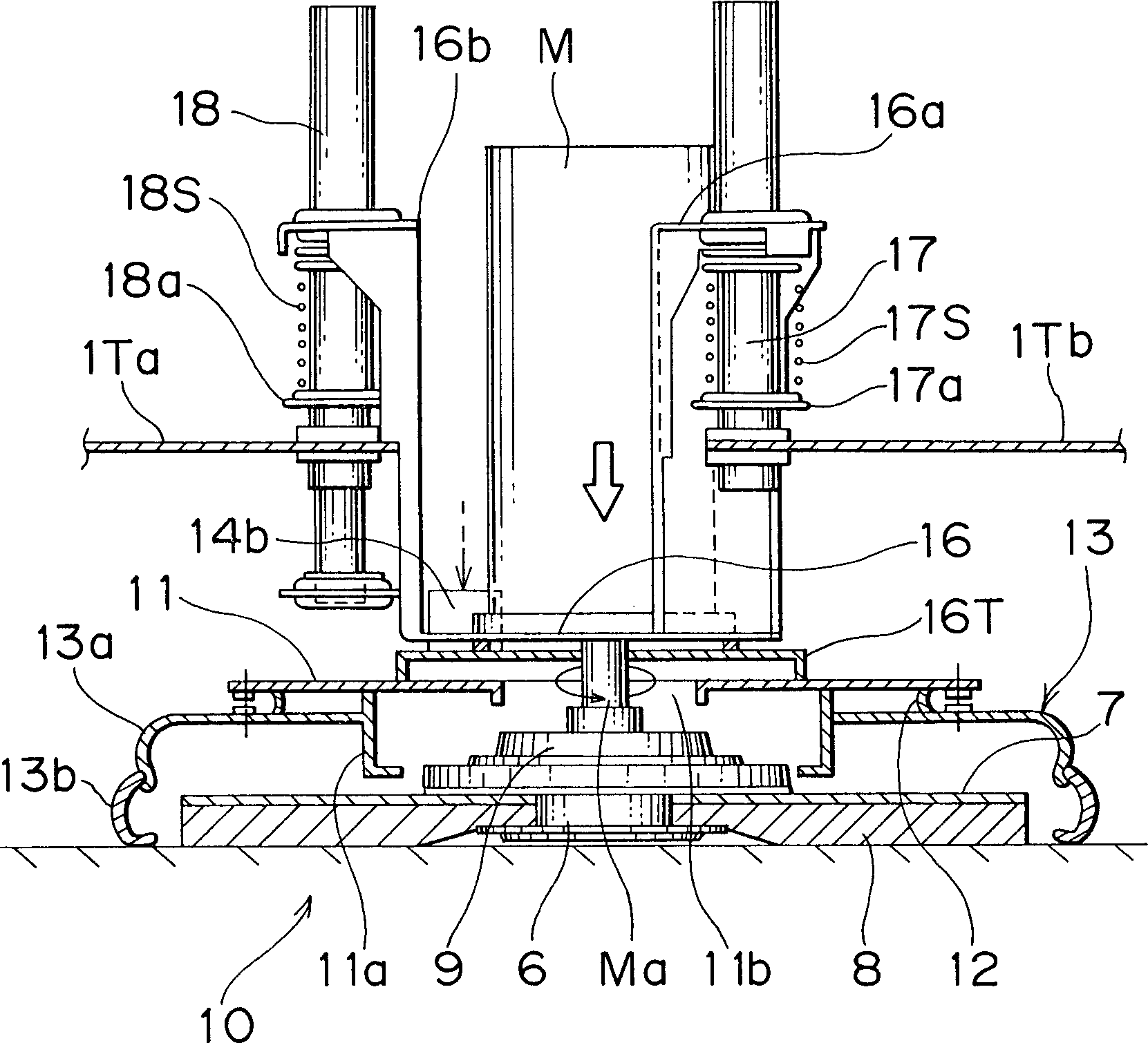
In
In
Das Kissen
In der Stufe
In der Stufe S4 werden der ermittelte
Stromwert und der Voreinstellwert in ähnlicher Weise miteinander
verglichen. Wenn der ermittelte Stromwert gleich dem oder größer als
der Voreinstellwert ist, schreitet das Programm zur Stufe
Das Erhöhen und Absenken des Stromwertes
des Motors M kann entweder durch automatisches Erhöhen oder
Absenken des Pegels Pegel um Pegel entsprechend dem Programm der
Steuereinrichtung
Da das mit einer Funktion zur Einstellung
des Kissendruckes ausgestattete Bodenreinigungsgerät in der
oben erwähnten
Weise aufgebaut ist, kann, wenn der Maschinenkörper
Wenn der Kontaktdruck (die Ansaugkraft) des
Kissens
Wie zuvor beschrieben wurde, kann, da das Bodenreinigungsgerät mit einer Funktion zur Einstellung des Kissendruckes ausgestattet ist, wenn die Druckkraft (Ansaugkraft) des Kissens gegen die Bodenfläche infolge von Ursachen verringert wird, wie eine Abnutzung des Kissens, eine Verringerung der Spannung der Batterien o. dgl., die Anpreßkraft auf ihren ursprünglichen Zustand durch geeignete Steuerung des Stromwertes des Kissenmotors zurückgestellt werden. Da die Bodenfläche daher stets mit einem konstanten Druck gereinigt werden kann, kann die gesamte Bodenfläche gleichmäßig sauber gereinigt werden.As previously described, because the floor cleaning device equipped with a function to adjust the cushion pressure is when the pressure force (suction force) of the cushion against the floor surface as a result of causes, such as wear of the pillow, is reduced Reducing the voltage of the batteries or the like, the contact pressure on their original Condition reset by suitable control of the current value of the cushion motor become. Because the floor area can therefore always be cleaned with a constant pressure entire floor area evenly clean getting cleaned.
Claims (4)
Applications Claiming Priority (2)
| Application Number | Priority Date | Filing Date | Title |
|---|---|---|---|
| JP05467894A JP3202474B2 (en) | 1994-02-28 | 1994-02-28 | Floor polishing machine with pad pressure adjustment function |
| JP6-54678 | 1994-02-28 |
Publications (2)
| Publication Number | Publication Date |
|---|---|
| DE19506552A1 DE19506552A1 (en) | 1995-09-21 |
| DE19506552B4 true DE19506552B4 (en) | 2004-02-12 |
Family
ID=12977455
Family Applications (1)
| Application Number | Title | Priority Date | Filing Date |
|---|---|---|---|
| DE19506552A Expired - Fee Related DE19506552B4 (en) | 1994-02-28 | 1995-02-24 | Floor cleaning device |
Country Status (3)
| Country | Link |
|---|---|
| US (1) | US5615437A (en) |
| JP (1) | JP3202474B2 (en) |
| DE (1) | DE19506552B4 (en) |
Families Citing this family (32)
| Publication number | Priority date | Publication date | Assignee | Title |
|---|---|---|---|---|
| JPH09215644A (en) * | 1996-02-07 | 1997-08-19 | Johnson Kk | Automatic floor cleaner |
| DE69608408T2 (en) * | 1996-02-09 | 2000-09-21 | Unilever N.V., Rotterdam | Device for working a surface with a rotating element |
| GB9703528D0 (en) * | 1996-09-04 | 1997-04-09 | Briscoe William A | Surface working apparatus |
| IT1294137B1 (en) * | 1997-06-25 | 1999-03-22 | Electrolux Euroclean Italia Sp | sweeper |
| US6163915A (en) * | 1997-09-04 | 2000-12-26 | Minuteman International, Inc. | Control system for floor care machine |
| US5928067A (en) * | 1997-10-14 | 1999-07-27 | Beloit Technologies, Inc. | Headbox apron finishing and lapping device |
| USRE39581E1 (en) * | 1997-10-22 | 2007-04-24 | Alto U.S., Inc. | Brush head positioning system |
| DE19857628A1 (en) * | 1998-12-14 | 2000-06-15 | Stein & Co Gmbh | Floor care equipment |
| US20010009047A1 (en) * | 1999-05-06 | 2001-07-26 | Eugene Bernstein | Compact burnisher |
| EP1297608B1 (en) | 2000-05-09 | 2009-08-12 | Tennant Company | Linear actuator control structure |
| AU779644B2 (en) * | 2000-10-31 | 2005-02-03 | Samsung Gwangju Electronics Co., Ltd. | Suction port assembly of vacuum cleaner |
| WO2002094077A1 (en) * | 2001-05-21 | 2002-11-28 | Tennant Company | Control system for a floor maintenance appliance |
| US20020170130A1 (en) * | 2001-05-21 | 2002-11-21 | Kevin Shinler | Suspension for a surface maintenance appliance |
| WO2002094075A2 (en) * | 2001-05-21 | 2002-11-28 | Tennant Company | Suspension device for floor maintenance appliance |
| US7313839B2 (en) | 2001-05-29 | 2008-01-01 | Tennant Company | Sweeping system with front removable hopper |
| AU2002301415B2 (en) * | 2001-10-12 | 2007-10-04 | Karcher North America, Inc. | Scrubbing machine passive recycling |
| US20030192573A1 (en) * | 2002-04-16 | 2003-10-16 | Loi Tran | Floor care machine with counter acting force |
| ATE342685T1 (en) * | 2004-05-07 | 2006-11-15 | Johnson Diversey Inc | SOIL TREATMENT AND CLEANING SYSTEM |
| US7020576B2 (en) * | 2004-05-26 | 2006-03-28 | Tennant Company | Back EMF actuator control |
| DE102005062587A1 (en) * | 2005-12-27 | 2007-06-28 | Robert Bosch Gmbh | Grinding system for grinding workpieces has control unit prepared to provide automatic steering of grinding tool through control of movement device |
| DE102007019947B3 (en) | 2007-04-27 | 2008-07-24 | Stein & Co. Gmbh | Floor care machine e.g. floor polisher, has drive unit consisting of sub units, which have rolling surfaces as opposite surface to rolling surfaces of spoke units and rolling body connected as intermediate element to surfaces |
| DE102009018121A1 (en) * | 2009-04-09 | 2010-10-14 | Alfred Kärcher Gmbh & Co. Kg | Method for operating a cleaning device and cleaning device and cleaning tool for performing the method |
| DE102009033944A1 (en) | 2009-07-14 | 2011-01-20 | Alfred Kärcher Gmbh & Co. Kg | Cleaning device and method for controlling access to a cleaning device |
| US8966693B2 (en) | 2009-08-05 | 2015-03-03 | Karcher N. America, Inc. | Method and apparatus for extended use of cleaning fluid in a floor cleaning machine |
| DE102010042347A1 (en) | 2010-10-12 | 2012-04-12 | Alfred Kärcher Gmbh & Co. Kg | Method for operating a cleaning device and cleaning device for carrying out the method |
| EP3302205A4 (en) * | 2015-06-04 | 2019-04-03 | Nilfisk, Inc. | Scrubber machine |
| CN105133477B (en) * | 2015-07-24 | 2017-06-20 | 吴聪颖 | It is a kind of can quick heat radiating intelligent road construction device |
| CN106264351B (en) * | 2016-09-23 | 2020-04-17 | 广州市白云清洁用品有限公司 | Brush disc mounting and dismounting structure and mounting and dismounting method |
| CN108797478B (en) * | 2018-07-28 | 2020-12-29 | 安徽南博机器人有限公司 | A hand-push type sweeping and washing machine |
| US11187377B2 (en) | 2018-11-15 | 2021-11-30 | Taylor Tools | Overload control device for rotating machinery |
| CN111202473A (en) * | 2020-01-10 | 2020-05-29 | 上海高仙自动化科技发展有限公司 | Adjusting device and cleaning robot with same |
| IT202100008120A1 (en) * | 2021-03-31 | 2022-10-01 | Diversey Inc | FLOOR CLEANING EQUIPMENT |
Citations (3)
| Publication number | Priority date | Publication date | Assignee | Title |
|---|---|---|---|---|
| JPH01131640A (en) * | 1987-11-17 | 1989-05-24 | Amano Corp | Polisher for floor surface |
| JPH0493054U (en) * | 1990-12-27 | 1992-08-13 | ||
| DE3874834T2 (en) * | 1987-07-27 | 1993-03-11 | Tennant Co | TORQUE CONTROL BY MOTOR LOAD IN FLOOR WIPERS. |
Family Cites Families (5)
| Publication number | Priority date | Publication date | Assignee | Title |
|---|---|---|---|---|
| US3496681A (en) * | 1965-11-16 | 1970-02-24 | Fred A Oswald | Floor grinding machine |
| GB8421713D0 (en) * | 1984-08-28 | 1984-10-03 | Unilever Plc | Floor-cleaning machine |
| JPH01131634A (en) * | 1987-11-17 | 1989-05-24 | Toyo Seikan Kaisha Ltd | Metal container for electronic range |
| US5177828A (en) * | 1991-08-20 | 1993-01-12 | Windsor Industries, Inc. | Missing pad detector for a floor polishing tool |
| US5253384A (en) * | 1992-04-16 | 1993-10-19 | Pioneer/Eclipse Corporation | Floor buffing machine with automatic pad pressure adjustment |
-
1994
- 1994-02-28 JP JP05467894A patent/JP3202474B2/en not_active Expired - Lifetime
-
1995
- 1995-02-21 US US08/391,036 patent/US5615437A/en not_active Expired - Fee Related
- 1995-02-24 DE DE19506552A patent/DE19506552B4/en not_active Expired - Fee Related
Patent Citations (4)
| Publication number | Priority date | Publication date | Assignee | Title |
|---|---|---|---|---|
| DE3874834T2 (en) * | 1987-07-27 | 1993-03-11 | Tennant Co | TORQUE CONTROL BY MOTOR LOAD IN FLOOR WIPERS. |
| JPH01131640A (en) * | 1987-11-17 | 1989-05-24 | Amano Corp | Polisher for floor surface |
| US4910824A (en) * | 1987-11-17 | 1990-03-27 | Amano Corporation | Floor polisher |
| JPH0493054U (en) * | 1990-12-27 | 1992-08-13 |
Also Published As
| Publication number | Publication date |
|---|---|
| JP3202474B2 (en) | 2001-08-27 |
| JPH07236604A (en) | 1995-09-12 |
| US5615437A (en) | 1997-04-01 |
| DE19506552A1 (en) | 1995-09-21 |
Similar Documents
| Publication | Publication Date | Title |
|---|---|---|
| DE19506552B4 (en) | Floor cleaning device | |
| EP2875767B1 (en) | Vacuum cleaner and method for operating same | |
| DE102010001030B4 (en) | Cordless hand tool and method for operating a cordless hand tool | |
| DE10231384A1 (en) | Method for operating a floor cleaning system and floor cleaning system for applying the method | |
| WO2012076418A1 (en) | Grinding device for mechanically grinding rotor blades for wind power plants | |
| EP2734098B1 (en) | Power sweeper having pressure vessel for cleaning the filter | |
| DE69310699T2 (en) | Device for collecting waste and dust | |
| EP0887460A1 (en) | Process and apparatus to clean a transport band | |
| DE102006009213A1 (en) | vacuum cleaner | |
| DE1928576A1 (en) | Method and device for separating textile fibers and the like. from an air stream | |
| DE212021000112U1 (en) | A lint removal and leveling device used in the manufacture of medical protective clothing fabrics | |
| DE102004044399A1 (en) | Apparatus for cleaning lubricant for dry-type wire drawing comprises case with holes for passing steel wire, rotating members connected to driving motors by belts to rotate motors and cleaning members coupled to rotating member | |
| DE102018118077A1 (en) | Suction device, laser processing machine and method for suction | |
| AT409332B (en) | WET VACUUM | |
| DE4231329B4 (en) | Bahnzuschneidvorrichtung | |
| EP3730024A1 (en) | Vacuum cleaner and method for controlling a cleaning process in a vacuum cleaner | |
| EP2789283A1 (en) | Suction device and method for operating the same | |
| EP3136012A1 (en) | Mobile dedusting device | |
| DE102015119498B4 (en) | Device and method for dehumidifying porous building material layers | |
| DE202023106374U1 (en) | Automatic tire scraper | |
| DE102020133149B4 (en) | Dedusting device with a controller for at least two operating modes and method for controlling a dedusting device | |
| DE4416541A1 (en) | Method and device for cleaning a circulating air stream | |
| DE102022128374A1 (en) | Repair system and process for professional repair or manufacture of Venetian blinds | |
| DE2925587C2 (en) | Device for evacuating waste materials by means of suction air | |
| DE102011055113A1 (en) | Energy-saving flow control device for dust removal system of asynchronous engine, has controllable valve device that determines free cross-section of suction channel for flow control |
Legal Events
| Date | Code | Title | Description |
|---|---|---|---|
| 8110 | Request for examination paragraph 44 | ||
| 8328 | Change in the person/name/address of the agent |
Representative=s name: HANSMANN & VOGESER, 81369 MUENCHEN |
|
| 8364 | No opposition during term of opposition | ||
| 8339 | Ceased/non-payment of the annual fee |