DE102020200073A1 - Guide vane ring - Google Patents
Guide vane ring Download PDFInfo
- Publication number
- DE102020200073A1 DE102020200073A1 DE102020200073.5A DE102020200073A DE102020200073A1 DE 102020200073 A1 DE102020200073 A1 DE 102020200073A1 DE 102020200073 A DE102020200073 A DE 102020200073A DE 102020200073 A1 DE102020200073 A1 DE 102020200073A1
- Authority
- DE
- Germany
- Prior art keywords
- inner ring
- guide vane
- ring
- wear
- side walls
- Prior art date
- Legal status (The legal status is an assumption and is not a legal conclusion. Google has not performed a legal analysis and makes no representation as to the accuracy of the status listed.)
- Withdrawn
Links
Images


Classifications
-
- F—MECHANICAL ENGINEERING; LIGHTING; HEATING; WEAPONS; BLASTING
- F01—MACHINES OR ENGINES IN GENERAL; ENGINE PLANTS IN GENERAL; STEAM ENGINES
- F01D—NON-POSITIVE DISPLACEMENT MACHINES OR ENGINES, e.g. STEAM TURBINES
- F01D9/00—Stators
- F01D9/02—Nozzles; Nozzle boxes; Stator blades; Guide conduits, e.g. individual nozzles
- F01D9/04—Nozzles; Nozzle boxes; Stator blades; Guide conduits, e.g. individual nozzles forming ring or sector
- F01D9/042—Nozzles; Nozzle boxes; Stator blades; Guide conduits, e.g. individual nozzles forming ring or sector fixing blades to stators
-
- F—MECHANICAL ENGINEERING; LIGHTING; HEATING; WEAPONS; BLASTING
- F01—MACHINES OR ENGINES IN GENERAL; ENGINE PLANTS IN GENERAL; STEAM ENGINES
- F01D—NON-POSITIVE DISPLACEMENT MACHINES OR ENGINES, e.g. STEAM TURBINES
- F01D25/00—Component parts, details, or accessories, not provided for in, or of interest apart from, other groups
- F01D25/24—Casings; Casing parts, e.g. diaphragms, casing fastenings
- F01D25/246—Fastening of diaphragms or stator-rings
-
- F—MECHANICAL ENGINEERING; LIGHTING; HEATING; WEAPONS; BLASTING
- F01—MACHINES OR ENGINES IN GENERAL; ENGINE PLANTS IN GENERAL; STEAM ENGINES
- F01D—NON-POSITIVE DISPLACEMENT MACHINES OR ENGINES, e.g. STEAM TURBINES
- F01D9/00—Stators
- F01D9/02—Nozzles; Nozzle boxes; Stator blades; Guide conduits, e.g. individual nozzles
- F01D9/04—Nozzles; Nozzle boxes; Stator blades; Guide conduits, e.g. individual nozzles forming ring or sector
- F01D9/041—Nozzles; Nozzle boxes; Stator blades; Guide conduits, e.g. individual nozzles forming ring or sector using blades
-
- F—MECHANICAL ENGINEERING; LIGHTING; HEATING; WEAPONS; BLASTING
- F05—INDEXING SCHEMES RELATING TO ENGINES OR PUMPS IN VARIOUS SUBCLASSES OF CLASSES F01-F04
- F05D—INDEXING SCHEME FOR ASPECTS RELATING TO NON-POSITIVE-DISPLACEMENT MACHINES OR ENGINES, GAS-TURBINES OR JET-PROPULSION PLANTS
- F05D2240/00—Components
- F05D2240/80—Platforms for stationary or moving blades
-
- F—MECHANICAL ENGINEERING; LIGHTING; HEATING; WEAPONS; BLASTING
- F05—INDEXING SCHEMES RELATING TO ENGINES OR PUMPS IN VARIOUS SUBCLASSES OF CLASSES F01-F04
- F05D—INDEXING SCHEME FOR ASPECTS RELATING TO NON-POSITIVE-DISPLACEMENT MACHINES OR ENGINES, GAS-TURBINES OR JET-PROPULSION PLANTS
- F05D2260/00—Function
- F05D2260/30—Retaining components in desired mutual position
- F05D2260/31—Retaining bolts or nuts
-
- F—MECHANICAL ENGINEERING; LIGHTING; HEATING; WEAPONS; BLASTING
- F05—INDEXING SCHEMES RELATING TO ENGINES OR PUMPS IN VARIOUS SUBCLASSES OF CLASSES F01-F04
- F05D—INDEXING SCHEME FOR ASPECTS RELATING TO NON-POSITIVE-DISPLACEMENT MACHINES OR ENGINES, GAS-TURBINES OR JET-PROPULSION PLANTS
- F05D2260/00—Function
- F05D2260/96—Preventing, counteracting or reducing vibration or noise
Abstract
Die Erfindung betrifft einen Leitschaufelkranz (1), der in eine obere und in eine untere Leitschaufelkranzhälfte unterteilt ist, mit einem zumindest zweigeteilten Innenring (2), der einen im Wesentlichen U-förmigen Querschnitt aufweist und einen sich in Umfangsrichtung erstreckenden, radial auswärts offenen Strömungskanal (9) bildet, der durch eine Innenringbodenwand (10) und zwei Innenringseitenwände (11) begrenzt ist, und einer Vielzahl von Leitschaufeln (4) aufnehmenden, entlang des Außenumfangs des Innenrings (2) angeordneten Schaufelplattformen (5), die jeweils radial einwärts vorstehende, in axialer Richtung voneinander beabstandete Haltestege (8) aufweisen, welche die Innenringseitenwände (11) von außen umgreifen, dadurch gekennzeichnet, dass in zwischen Haltestegen (8) und unmittelbar benachbart angeordneten Innenringseitenwänden (11) vorhandene Spalte Verschleißelemente (12) eingesetzt sind.The invention relates to a guide vane ring (1), which is divided into an upper and a lower guide vane ring half, with an inner ring (2) which is at least two-part and has a substantially U-shaped cross section and a radially outwardly open flow channel extending in the circumferential direction (9), which is delimited by an inner ring bottom wall (10) and two inner ring side walls (11), and a plurality of guide vanes (4) accommodating vane platforms (5) arranged along the outer circumference of the inner ring (2), each of which projects radially inward , have holding webs (8) spaced apart from one another in the axial direction, which encompass the inner ring side walls (11) from the outside, characterized in that wear elements (12) are inserted in gaps between holding webs (8) and immediately adjacent inner ring side walls (11).
Description
Die Erfindung betrifft einen Leitschaufelkranz, der in eine obere und in eine untere Leitschaufelkranzhälfte unterteilt ist, mit einem zumindest zweigeteilten Innenring, der einen im Wesentlichen U-förmigen Querschnitt aufweist und einen sich in Umfangsrichtung erstreckenden, radial auswärts offenen Strömungskanal bildet, der durch eine Innenringbodenwand und zwei Innenringseitenwände begrenzt ist, und einer Vielzahl von Leitschaufeln aufnehmenden, entlang des Außenumfangs des Innenrings angeordneten Schaufelplattformen, die jeweils radial einwärts vorstehende, in axialer Richtung voneinander beabstandete Haltestege aufweisen, welche die Innenringseitenwände von außen umgreifen.The invention relates to a guide vane ring, which is divided into an upper and a lower guide vane ring half, with an inner ring that is at least two-part, has a substantially U-shaped cross section and forms a circumferentially extending, radially outwardly open flow channel which is formed by an inner ring bottom wall and two inner ring side walls is delimited, and a plurality of guide vanes receiving, arranged along the outer circumference of the inner ring vane platforms, each having radially inwardly projecting, axially spaced apart retaining webs which surround the inner ring side walls from the outside.
Leitschaufeln werden bei axial durchströmten Turbinen eingesetzt. So bildet ein am Stator angeordneter Leitschaufelkranz gemeinsam mit einem am Rotor vorgesehenen Laufschaufelkranz eine Stufe einer Turbine. Die Aufgabe der Leitschaufeln besteht darin, das die Turbine durchströmende Medium möglichst effektiv auf die zugeordneten Laufschaufeln zu lenken. Ein Leitschaufelkranz weist normalerweise einen Innenring, einen Außenring und eine Vielzahl von sich zwischen dem Innenring und dem Außenring erstreckenden Leitschaufeln auf. Aus Gründen der Montage ist der Leitschaufelkranz in eine untere und in eine obere Leitschaufelkranzhälfte unterteilt, weshalb auch der Innenring und der Außenring zumindest zweigeteilt ausgeführt sind. Die Leitschaufeln umfassen äußere und inneren Schaufelplattformen, zwischen denen sich die Schaufelblätter erstrecken. Die äußeren Schaufelplattformen sind über radial auswärts vorstehende Schaufelfüße an dem Außenring befestigt. Die inneren Schaufelplattformen zumindest der oberen Leitschaufelkranzhälfte weisen bei einer Leitschaufelkranzbauart radial einwärts vorstehende, in axialer Richtung voneinander beabstandete Haltestege auf, welche den Innenring von außen umgreifen. Diese Haltestege werden beim Zusammenfügen der oberen und unteren Leitschaufelkranzhälfte von oben auf den Innenring mit geringem Spiel, das normalerweise etwa 2-3mm beträgt, derart aufgeschoben, dass sie den Innenring zwischen sich aufnehmen. Der Innenring weist einen im Wesentlichen U-förmigen Querschnitt aufweist und bildet einen sich in Umfangsrichtung erstreckenden, radial auswärts offenen Strömungskanal, der durch eine Innenringbodenwand und zwei Innenringseitenwände begrenzt ist. In diesen Strömungskanal wird während des Turbinenbetriebs ein aus den Schaufelblättern der Leitschaufeln ausströmendes Kühlmedium eingeleitet, um dieses dann zur Kühlung der Laufschaufeln in Richtung der Laufschaufeln weiterzuleiten. Der als Kühlmediumverteiler dienende Innenring wird in der Praxis auch häufig als Preswirler bezeichnet.Guide vanes are used in turbines with axial flow. A guide vane ring arranged on the stator, together with a rotor blade ring provided on the rotor, forms a stage of a turbine. The task of the guide vanes is to direct the medium flowing through the turbine as effectively as possible onto the associated rotor blades. A guide vane ring normally has an inner ring, an outer ring and a plurality of guide vanes extending between the inner ring and the outer ring. For reasons of assembly, the guide vane ring is divided into a lower and an upper guide vane ring half, which is why the inner ring and the outer ring are designed to be at least two-part. The vanes include outer and inner vane platforms between which the airfoils extend. The outer vane platforms are attached to the outer ring via radially outwardly projecting vane roots. The inner vane platforms of at least the upper guide vane ring half have, in the case of a guide vane ring type, holding webs which protrude radially inward and are spaced apart in the axial direction and which encompass the inner ring from the outside. When the upper and lower guide vane ring halves are joined together, these retaining webs are pushed onto the inner ring from above with little play, which is normally around 2-3mm, in such a way that they accommodate the inner ring between them. The inner ring has an essentially U-shaped cross section and forms a flow channel which extends in the circumferential direction and is open radially outward and which is delimited by an inner ring bottom wall and two inner ring side walls. During operation of the turbine, a cooling medium flowing out of the blade blades of the guide vanes is introduced into this flow channel in order to then pass it on in the direction of the rotor blades in order to cool the rotor blades. The inner ring, which serves as a coolant distributor, is also often referred to in practice as a preswirler.
Während des Turbinenbetriebs verschleißen die Turbinenkomponenten und müssen im Rahmen von Wartungsarbeiten aufgearbeitet oder ersetzt werden. Dies gilt auch für den Innenring. So zeigen beispielsweise zu den Haltestegen der Leitschaufeln weisenden Außenflächenbereiche der Innenringseitenwände regelmäßig Verschleißerscheinungen aufgrund von während des Betriebs auftretenden Deformationen und/oder Belastungen, deren Reparatur mit großem Aufwand verbunden ist und zu einer deutlichen Verlängerung der Wartungszeiten führt.The turbine components wear out during turbine operation and have to be refurbished or replaced as part of maintenance work. This also applies to the inner ring. For example, the outer surface areas of the inner ring side walls facing the retaining webs of the guide vanes regularly show signs of wear due to deformations and / or loads occurring during operation, the repair of which is associated with great effort and leads to a significant increase in maintenance times.
Ausgehend von diesem Stand der Technik ist es eine Aufgabe der vorliegenden Erfindung, einen Leitschaufelkranz mit alternativem Aufbau zu schaffen, mit dem die zuvor beschriebenen Probleme zumindest teilweise behoben werden.Based on this prior art, it is an object of the present invention to create a guide vane ring with an alternative structure with which the problems described above are at least partially eliminated.
Zur Lösung dieser Aufgabe schafft die vorliegende Erfindung einen Leitschaufelkranz der eingangs genannten Art, der dadurch gekennzeichnet ist, dass in zwischen Haltestegen und unmittelbar benachbart angeordneten Innenringseitenwänden vorhandene Spalte Verschleißelemente eingesetzt sind. Derartige Verschleißelemente gleichen das zwischen Haltestegen und unmittelbar benachbart angeordneten Innenringseitenwänden vorhandene Spiel aus und verhindern einen unmittelbaren Kontakt zwischen den Haltestegen und den Innenringseitenwänden, der ohne solche Verschleißelemente aufgrund während des Turbinenbetriebs angeregter Schwingungen der Einzelkomponenten stattfinden kann. Der Verschleiß wird durch den Einsatz erfindungsgemäßer Verschleißelemente zum einen verringert. Zum anderen verschleißen vornehmlich die Verschleißelemente, die im Rahmen von Wartungsarbeiten schnell, einfach und günstig ersetzt werden können. Eine Instandsetzung des Innenrings im Bereich der Haltestege entfällt damit ganz oder fällt sehr geringfügig aus.To solve this problem, the present invention creates a guide vane ring of the type mentioned at the outset, which is characterized in that wear elements are inserted in gaps present between retaining webs and inner ring side walls arranged immediately adjacent. Wear elements of this type compensate for the play existing between retaining webs and immediately adjacent inner ring side walls and prevent direct contact between the holding webs and inner ring side walls, which can take place without such wear elements due to vibrations of the individual components excited during turbine operation. On the one hand, wear is reduced by using wear elements according to the invention. On the other hand, it is primarily the wear elements that wear out, which can be replaced quickly, easily and cheaply during maintenance work. A repair of the inner ring in the area of the retaining webs is therefore not necessary at all or is very minor.
Bevorzugt sind die Verschleißelemente plattenförmig ausgebildet, um auf diese Weise die auftretenden mechanischen Lasten auf eine möglichst große Fläche zu verteilen, wodurch der Verschleiß und die Beeinträchtigung des Innenrings weiter reduziert werden.Preferably, the wear elements are plate-shaped in order to distribute the occurring mechanical loads over the largest possible area, whereby the wear and the impairment of the inner ring are further reduced.
Vorteilhaft sind die Verschleißelemente aus demjenigen Material herstellt, aus dem der Innenring gefertigt ist, oder aus einem weicheren Material, um den Verschleiß in erster Linie auf die Verschleißelemente zu konzentrieren.The wear elements are advantageously made from the material from which the inner ring is made, or from a softer material in order to concentrate the wear primarily on the wear elements.
Gemäß einer Ausgestaltung der vorliegenden Erfindung ist jedes Verschleißelement mit einem Haltesteg oder mit einer Innenringseitenwand lösbar verbunden. Entsprechend lassen sich die Verschleißelemente im Rahmen von Wartungsarbeiten schnell und einfach austauschen.According to one embodiment of the present invention, each wear element is releasably connected to a retaining web or to an inner ring side wall. Accordingly, the Replace wear elements quickly and easily as part of maintenance work.
Bevorzugt ist jedes Verschleißelement unter Einsatz einer Schraubverbindung an einem Haltesteg oder an einer Innenringseitenwand befestigt. Auf diese Weise wird eine einfache lösbare Verbindung geschaffen. Vorteilhaft weist jedes Verschleißelement hierzu zumindest einen angeschweißten Gewindebolzen auf, der beispielsweise durch eine Öffnung eines Haltestegs oder der Innenringseitenwand geführt und auf der anderen Seite mit einer Mutter gesichert werden kann.Each wear element is preferably fastened to a retaining web or to an inner ring side wall using a screw connection. In this way, a simple detachable connection is created. For this purpose, each wear element advantageously has at least one welded-on threaded bolt which, for example, can be guided through an opening in a retaining web or the inner ring side wall and secured on the other side with a nut.
Es können die Verschleißelemente aufnehmende Vertiefungen an Innenflächen von Haltestegen und/oder an der Außenfläche zumindest einer Innenringseitenwand vorgesehen sein, um eine definierte Positionierung der Verschleißelemente bei ihrer Montage sicherzustellen.Depressions receiving the wear elements can be provided on inner surfaces of retaining webs and / or on the outer surface of at least one inner ring side wall in order to ensure a defined positioning of the wear elements during their assembly.
Gemäß einer Ausgestaltung der vorliegenden Erfindung sind Verschleißelemente in zwischen Haltestegführungsvorsprüngen und unmittelbar benachbart angeordneten Innenringseitenwänden vorhandene Spalte eingesetzt, wobei die Haltestegführungsvorsprünge jeweils radial einwärts vorstehen. Dank solcher Führungsvorsprünge wird die Montage des Leitschaufelkranzes deutlich erleichtert.According to one embodiment of the present invention, wear elements are inserted into gaps present between holding web guide projections and inner ring side walls arranged immediately adjacent, the holding web guide projections each protruding radially inward. Thanks to such guide projections, the assembly of the guide vane ring is made significantly easier.
Weitere Merkmale und Vorteile der vorliegenden Erfindung werden anhand der nachfolgenden Beschreibung eines Ausführungsform eines erfindungsgemäßen Leitschaufelkranzes unter Bezugnahme auf die beiliegende Zeichnung deutlich. Darin ist
-
1 eine schematische Vorderansicht einer oberen Hälfte eines Leitschaufelkranzes gemäß einer Ausführungsform der vorliegenden Erfindung; -
2 eine perspektivische schematische Teilansicht des in1 dargestellten Leitschaufelkranzes im teilweise montierten Zustand, das ein Verschleißelement zeigt, das gemäß einer ersten erfindungsgemäßen Variante ausgebildet ist; -
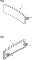
3 eine perspektivische schematische Vorderansicht des in2 gezeigten Verschleißelementes; -
4 eine perspektivische schematische Rückansicht des in2 gezeigten Verschleißelementes -
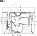
5 eine perspektivische schematische Schnittansicht des in1 dargestellten Leitschaufelkranzes, das ein Verschleißelement zeigt, das gemäß einer zweiten erfindungsgemäßen Variante ausgebildet ist; -
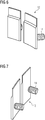
6 eine perspektivische schematische Vorderansicht des in5 gezeigten Verschleißelementes; -
7 eine perspektivische schematische Rückansicht des in5 gezeigten Verschleißelementes und -
8 eine perspektivische schematische Teilansicht eines Innenrings der in5 gezeigten Anordnung.
-
1 a schematic front view of an upper half of a guide vane ring according to an embodiment of the present invention; -
2 a perspective schematic partial view of the in1 guide vane ring shown in the partially assembled state, which shows a wear element which is designed according to a first variant of the invention; -
3 a perspective schematic front view of the in2 wear element shown; -
4th a perspective schematic rear view of the in2 shown wear element -
5 a perspective schematic sectional view of the in1 illustrated guide vane ring, which shows a wear element which is formed according to a second variant of the invention; -
6th a perspective schematic front view of the in5 wear element shown; -
7th a perspective schematic rear view of the in5 shown wear element and -
8th a perspective schematic partial view of an inner ring of FIG5 arrangement shown.
Gleiche Bezugsziffern kennzeichnen nachfolgend gleiche oder gleichartige Bauteile bzw. Bauteilabschnitte.The same reference numbers denote the same or similar components or component sections below.
Der Leitschaufelkranz
Die Leitschaufeln umfassen äußere und inneren Schaufelplattformen
Die inneren Schaufelplattformen
In die zwischen den Haltestegen
Die Verschleißelemente
Alternativ können die Verschleißelemente
Jedes Verschleißelement
Die
Pro Haltesteg
Im Übrigen entspricht der Aufbau des in den
Die erfindungsgemäßen Verschleißelemente
Der Verschleiß wird durch den Einsatz erfindungsgemäßer Verschleißelemente
Die Verschleißelemente
Obwohl die Erfindung im Detail durch das bevorzugte Ausführungsbeispiel näher illustriert und beschrieben wurde, so ist die Erfindung nicht durch die offenbarten Beispiele eingeschränkt und andere Variationen können vom Fachmann hieraus abgeleitet werden, ohne den Schutzumfang der Erfindung zu verlassen.Although the invention has been illustrated and described in more detail by the preferred exemplary embodiment, the invention is not restricted by the disclosed examples and other variations can be derived therefrom by the person skilled in the art without departing from the scope of protection of the invention.
Claims (8)
Priority Applications (6)
| Application Number | Priority Date | Filing Date | Title |
|---|---|---|---|
| DE102020200073.5A DE102020200073A1 (en) | 2020-01-07 | 2020-01-07 | Guide vane ring |
| KR1020227026844A KR20220116333A (en) | 2020-01-07 | 2020-12-07 | Guide vane rings with wear elements |
| CN202080092166.4A CN114945733B (en) | 2020-01-07 | 2020-12-07 | Guide vane ring with wear element |
| US17/788,932 US11965432B2 (en) | 2020-01-07 | 2020-12-07 | Guide vane ring with wear elements |
| EP20828833.2A EP4058657A1 (en) | 2020-01-07 | 2020-12-07 | Guide vane ring with wear elements |
| PCT/EP2020/084894 WO2021139939A1 (en) | 2020-01-07 | 2020-12-07 | Guide vane ring with wear elements |
Applications Claiming Priority (1)
| Application Number | Priority Date | Filing Date | Title |
|---|---|---|---|
| DE102020200073.5A DE102020200073A1 (en) | 2020-01-07 | 2020-01-07 | Guide vane ring |
Publications (1)
| Publication Number | Publication Date |
|---|---|
| DE102020200073A1 true DE102020200073A1 (en) | 2021-07-08 |
Family
ID=73943292
Family Applications (1)
| Application Number | Title | Priority Date | Filing Date |
|---|---|---|---|
| DE102020200073.5A Withdrawn DE102020200073A1 (en) | 2020-01-07 | 2020-01-07 | Guide vane ring |
Country Status (6)
| Country | Link |
|---|---|
| US (1) | US11965432B2 (en) |
| EP (1) | EP4058657A1 (en) |
| KR (1) | KR20220116333A (en) |
| CN (1) | CN114945733B (en) |
| DE (1) | DE102020200073A1 (en) |
| WO (1) | WO2021139939A1 (en) |
Citations (2)
| Publication number | Priority date | Publication date | Assignee | Title |
|---|---|---|---|---|
| US4384822A (en) * | 1980-01-31 | 1983-05-24 | Motoren- Und Turbinen-Union Munchen Gmbh | Turbine nozzle vane suspension for gas turbine engines |
| US20120128481A1 (en) * | 2008-11-26 | 2012-05-24 | Snecma | Anti-wear device for the blades of a turbine distributor in an aeronautical turbine engine |
Family Cites Families (38)
| Publication number | Priority date | Publication date | Assignee | Title |
|---|---|---|---|---|
| US3070353A (en) | 1958-12-03 | 1962-12-25 | Gen Motors Corp | Shroud assembly |
| US4126405A (en) * | 1976-12-16 | 1978-11-21 | General Electric Company | Turbine nozzle |
| US5118120A (en) * | 1989-07-10 | 1992-06-02 | General Electric Company | Leaf seals |
| GB8922339D0 (en) * | 1989-10-04 | 1989-11-22 | Rolls Royce Plc | Improvements in or relating to labyrinth seal structures |
| US5429478A (en) * | 1994-03-31 | 1995-07-04 | United Technologies Corporation | Airfoil having a seal and an integral heat shield |
| DE19507673C2 (en) * | 1995-03-06 | 1997-07-03 | Mtu Muenchen Gmbh | Guide wheel for turbomachinery |
| US5630590A (en) * | 1996-03-26 | 1997-05-20 | United Technologies Corporation | Method and apparatus for improving the airsealing effectiveness in a turbine engine |
| EP0943785A1 (en) | 1998-03-18 | 1999-09-22 | Asea Brown Boveri AG | Fixing a vane to a stator |
| US6220815B1 (en) | 1999-12-17 | 2001-04-24 | General Electric Company | Inter-stage seal retainer and assembly |
| DE60307302T2 (en) | 2003-12-18 | 2007-07-19 | Techspace Aero S.A. | Fastening device for stator blade, and Leitschaufelstufe a compressor with such a device |
| US7121785B2 (en) * | 2004-07-02 | 2006-10-17 | Siemens Power Generation, Inc. | Retraction retainer system for biased turbine engine components |
| FR2875270B1 (en) * | 2004-09-10 | 2006-12-01 | Snecma Moteurs Sa | RETENTION OF CENTERING KEYS OF STATOR UNDER RINGS WITH VARIABLE SETTING OF A GAS TURBINE ENGINE |
| US7527469B2 (en) * | 2004-12-10 | 2009-05-05 | Siemens Energy, Inc. | Transition-to-turbine seal apparatus and kit for transition/turbine junction of a gas turbine engine |
| US7837435B2 (en) | 2007-05-04 | 2010-11-23 | Power System Mfg., Llc | Stator damper shim |
| US7824152B2 (en) | 2007-05-09 | 2010-11-02 | Siemens Energy, Inc. | Multivane segment mounting arrangement for a gas turbine |
| EP2194230A1 (en) | 2008-12-05 | 2010-06-09 | Siemens Aktiengesellschaft | Guide blade assembly for an axial turbo engine |
| CH704140A1 (en) | 2010-11-29 | 2012-05-31 | Alstom Technology Ltd | Blade assembly for a rotating flow machine. |
| US8894378B2 (en) * | 2011-07-26 | 2014-11-25 | General Electric Company | Systems, methods, and apparatus for sealing a bucket dovetail in a turbine |
| GB201113893D0 (en) * | 2011-08-12 | 2011-09-28 | Rolls Royce Plc | Oil mist separation in gas turbine engines |
| EP2562356A1 (en) | 2011-08-24 | 2013-02-27 | Siemens Aktiengesellschaft | Blade assembly |
| EP2657454B1 (en) * | 2012-04-26 | 2014-05-14 | Alstom Technology Ltd | Turbine diaphragm construction |
| IN2014DN08366A (en) * | 2012-05-08 | 2015-05-08 | Siemens Ag | |
| FR3001252B1 (en) | 2013-01-23 | 2015-02-13 | Snecma | FIXED FLOW DISTRIBUTION AUBING COMPRISING AN INTEGRATED REINFORCED INTERNAL PLATFORM |
| EP2801702B1 (en) | 2013-05-10 | 2020-05-06 | Safran Aero Boosters SA | Inner shroud of turbomachine with abradable seal |
| EP2884052B1 (en) | 2013-12-13 | 2018-02-21 | Siemens Aktiengesellschaft | Rotor for a turbomachine having a closed flow contour ring and method for manufacturing the same |
| US20160010488A1 (en) | 2014-07-08 | 2016-01-14 | MTU Aero Engines AG | Wear protection arrangement for a turbomachine, process and compressor |
| EP3172410B1 (en) * | 2014-07-24 | 2018-05-16 | Siemens Aktiengesellschaft | Stator vane system usable within a gas turbine engine |
| EP3015655A1 (en) * | 2014-10-30 | 2016-05-04 | Siemens Aktiengesellschaft | Wheel disc assembly with seal plates |
| US9587517B2 (en) * | 2014-12-29 | 2017-03-07 | Rolls-Royce North American Technologies, Inc. | Blade track assembly with turbine tip clearance control |
| EP3075961A1 (en) | 2015-04-02 | 2016-10-05 | Siemens Aktiengesellschaft | Guide vane assembly |
| EP3085900B1 (en) | 2015-04-21 | 2020-08-05 | Ansaldo Energia Switzerland AG | Abradable lip for a gas turbine |
| DE102016202519A1 (en) * | 2016-02-18 | 2017-08-24 | MTU Aero Engines AG | Guide vane segment for a turbomachine |
| US11066951B2 (en) * | 2016-04-21 | 2021-07-20 | Raytheon Technologies Corporation | Wear liner for fixed stator vanes |
| GB201614711D0 (en) * | 2016-08-31 | 2016-10-12 | Rolls Royce Plc | Axial flow machine |
| FR3070718B1 (en) * | 2017-09-06 | 2019-08-23 | Safran Aircraft Engines | RING SECTOR TURBINE ASSEMBLY |
| CN110030037B (en) * | 2018-01-11 | 2021-08-13 | 中国航发商用航空发动机有限责任公司 | Turbine guide vane, turbine guide vane assembly and core machine |
| KR102142141B1 (en) * | 2018-08-17 | 2020-08-06 | 두산중공업 주식회사 | Turbine, gas turbine, and disassembling method of turbine blade |
| US11174742B2 (en) * | 2019-07-19 | 2021-11-16 | Rolls-Royce Plc | Turbine section of a gas turbine engine with ceramic matrix composite vanes |
-
2020
- 2020-01-07 DE DE102020200073.5A patent/DE102020200073A1/en not_active Withdrawn
- 2020-12-07 CN CN202080092166.4A patent/CN114945733B/en active Active
- 2020-12-07 EP EP20828833.2A patent/EP4058657A1/en active Pending
- 2020-12-07 WO PCT/EP2020/084894 patent/WO2021139939A1/en unknown
- 2020-12-07 US US17/788,932 patent/US11965432B2/en active Active
- 2020-12-07 KR KR1020227026844A patent/KR20220116333A/en unknown
Patent Citations (2)
| Publication number | Priority date | Publication date | Assignee | Title |
|---|---|---|---|---|
| US4384822A (en) * | 1980-01-31 | 1983-05-24 | Motoren- Und Turbinen-Union Munchen Gmbh | Turbine nozzle vane suspension for gas turbine engines |
| US20120128481A1 (en) * | 2008-11-26 | 2012-05-24 | Snecma | Anti-wear device for the blades of a turbine distributor in an aeronautical turbine engine |
Also Published As
| Publication number | Publication date |
|---|---|
| WO2021139939A1 (en) | 2021-07-15 |
| CN114945733A (en) | 2022-08-26 |
| US20230340886A1 (en) | 2023-10-26 |
| US11965432B2 (en) | 2024-04-23 |
| EP4058657A1 (en) | 2022-09-21 |
| KR20220116333A (en) | 2022-08-22 |
| CN114945733B (en) | 2023-10-20 |
Similar Documents
| Publication | Publication Date | Title |
|---|---|---|
| EP1766192B1 (en) | Vane wheel of a turbine comprising a vane and at least one cooling channel | |
| WO2000057031A1 (en) | Gas turbine rotor with internally-cooled gas turbine blade | |
| DE956822C (en) | Turbine blade for the rotor of a turbine | |
| EP1944472A1 (en) | Axial rotor section for a rotor in a turbine, sealing element for a turbine rotor equipped with rotor blades and rotor for a turbine | |
| CH700001A1 (en) | Moving blade arrangement, especially for a gas turbine. | |
| DE1426806A1 (en) | Wing body group | |
| WO1998044240A1 (en) | Surface structure for the wall of a flow channel or a turbine blade | |
| DE2144595A1 (en) | Cooled turbine blade | |
| DE19713268B4 (en) | Chilled gas turbine blade | |
| WO2013167346A1 (en) | Turbine rotor blade and axial rotor blade section for a gas turbine | |
| EP3574188B1 (en) | Method for sealing an annular gap in a turbine, and turbine | |
| EP2129871A1 (en) | Arrangement for axially securing rotating blades in a rotor, and gas turbine having such an arrangement | |
| WO2009000802A2 (en) | Guide vane for a gas turbine | |
| EP2092164B1 (en) | Turbomachine, particularly a gas turbine | |
| DE69815815T2 (en) | Guide blades for a turbomachine | |
| EP1253293A2 (en) | Attaching a rotor blade on a rotor of a turbomachine | |
| DE2155344A1 (en) | INTEGRAL TURBINE WHEEL WITH OPEN AXIAL BREAKTHROUGHTS ON THE OUTER WREATH AND CONTROLLED WREATH Cracks | |
| DE102020200073A1 (en) | Guide vane ring | |
| EP1284339A1 (en) | Annular cover plate system for gas turbine rotors | |
| EP3232001A1 (en) | Rotor blade for a turbine | |
| EP2907977A1 (en) | Component that can be charged with hot gas for a gas turbine and sealing assembly with such a component | |
| EP3232004A1 (en) | Turbine blade for a thermal turbomachine | |
| CH705377A1 (en) | A process for reconditioning a rotor of a turbomachine. | |
| EP3551853B1 (en) | Guide blade for a flow engine | |
| EP4134488B1 (en) | Milling wheel |
Legal Events
| Date | Code | Title | Description |
|---|---|---|---|
| R163 | Identified publications notified | ||
| R119 | Application deemed withdrawn, or ip right lapsed, due to non-payment of renewal fee |