EP2194230A1 - Guide blade assembly for an axial turbo engine - Google Patents
Guide blade assembly for an axial turbo engine Download PDFInfo
- Publication number
- EP2194230A1 EP2194230A1 EP08021215A EP08021215A EP2194230A1 EP 2194230 A1 EP2194230 A1 EP 2194230A1 EP 08021215 A EP08021215 A EP 08021215A EP 08021215 A EP08021215 A EP 08021215A EP 2194230 A1 EP2194230 A1 EP 2194230A1
- Authority
- EP
- European Patent Office
- Prior art keywords
- vane
- inner ring
- guide
- assembly
- head
- Prior art date
- Legal status (The legal status is an assumption and is not a legal conclusion. Google has not performed a legal analysis and makes no representation as to the accuracy of the status listed.)
- Withdrawn
Links
Images


Classifications
-
- F—MECHANICAL ENGINEERING; LIGHTING; HEATING; WEAPONS; BLASTING
- F01—MACHINES OR ENGINES IN GENERAL; ENGINE PLANTS IN GENERAL; STEAM ENGINES
- F01D—NON-POSITIVE DISPLACEMENT MACHINES OR ENGINES, e.g. STEAM TURBINES
- F01D9/00—Stators
- F01D9/02—Nozzles; Nozzle boxes; Stator blades; Guide conduits, e.g. individual nozzles
- F01D9/04—Nozzles; Nozzle boxes; Stator blades; Guide conduits, e.g. individual nozzles forming ring or sector
- F01D9/042—Nozzles; Nozzle boxes; Stator blades; Guide conduits, e.g. individual nozzles forming ring or sector fixing blades to stators
Definitions
- the invention relates to a vane assembly for an axial turbomachine comprising an annular vane carrier and an inner ring disposed concentrically with the vane carrier, between which a plurality of vanes are radiantly arranged, each vane being attached to the vane carrier.
- vane arrangement is sufficiently known from the prior art.
- this is known in compressors of stationary gas turbines, in which vanes of the compressor are attached to a vane support or on a compressor housing.
- known guide blade carrier which are formed in particular in most cases tubular, on its inner circumferential surfaces in the circumferential direction extending retaining grooves with undercuts in which guide vanes or outer rings are inserted and secured.
- the guide vanes may be formed as free-standing vanes, so that their airfoil tips lie opposite one another with the gap forming an inner boundary wall of the flow path of the compressor. It is also known that the inner boundary wall of the flow path is part of the vanes or can be held by the vanes themselves.
- the known guide vanes either have cover bands arranged on the top side, which then form parts of the boundary wall, or the guide vanes carry an inner ring on the top side, the outer surface of which then represents the inner boundary for the flow path.
- the attachment of the inner ring to the guide vanes of the vane assembly can be done via a suitable screw, by welding or by caulking.
- the object of the invention is therefore to provide an aforementioned vane arrangement for an axial turbomachine, which allows a particularly strain-tolerant, low-wear and reliable attachment of vanes to an inner ring.
- the inner ring of the vane arrangement is fastened resiliently over at least one of the guide vanes.
- all vanes of the vane assembly are resiliently connected to the inner ring.
- the invention is based on the finding that a rigid connection of guide vanes on the inner ring is disadvantageous. Accordingly, it proposes a type of connection which permits relative movements of guide vanes to inner ring without wear to a small extent, without damaging the connection. Consequently, the invention turns away from the previous approaches, in which a rigid, firm connection between vanes and inner ring was provided.
- a spring element is now to be used for fixing the guide vane on the inner ring.
- each respective vane on the inner ring side comprises a sunk in the inner ring vane head, by means of which the vane is resiliently mounted on the inner ring.
- the relevant vane on the inner ring is resiliently fastened, it comprises at least one structural element, namely the vane head, which is connectable to the inner ring and adapted to carry this.
- the guide vane head of each relevant vane comprises a web, which is in each case arranged in an outwardly open, arranged on the inner ring recess and in which in at least one of the respective web facing side surface of the recess, a spring element is arranged, which bears against the inner ring and the web of the relevant vane biased.
- the spring element provided, which is supported on the one hand on the inner ring and on the other hand at the web of the relevant vane.
- the guide vane assembly is designed so that the spring element is biased and thus the web of the relevant vane either indirectly or directly to the inner ring, in detail to one of the two side surfaces of the recess pressed.
- the guide vane head is hammer-shaped by means of the web and a head part extending transversely thereto, wherein the web connects the head part with an aerodynamically curved airfoil of the relevant vane and wherein the inner ring has a circumferential groove corresponding to the vane head for receiving the vane heads, which groove each in the section between two adjacent vanes of a cover, so the blade is closed.
- This embodiment is particularly advantageous when the vane assembly itself, the inner ring and / or the annular vane support is not formed integrally, but are formed by at least two arcuate ring segments, which in each case separate from the other ring segments during assembly and / or disassembly be handled.
- the cover prevents on the one hand a displacement of the inner ring relative to the Vanes along the circumference, since the cover is arranged between two vanes and thus blocks the displacement along the groove.
- the cover also provides for a stepless boundary surface of the flow channel.
- each relevant vane which are arranged on opposite side surfaces of the recess.
- each such mounted vane is indirectly, so arranged biased on the inner ring via the spring elements.
- the spring force of each spring element is directed in the circumferential direction of the inner ring. If a clamping sleeve is used as the spring element, only a line contact is present between the web of each relevant vane and the clamping sleeve, whereby the static load on the vane at the connection point is less than in a flat fixed guide vane. Since the static load is mainly due to an occurring displacement of the inner ring in the circumferential direction caused by an aerodynamic blade load, a displacement-tolerant mounting in the form of a resilient mounting in the circumferential direction is required to avoid wear and cracking and crack growth.
- the inner ring comprises two partial rings, which can be mounted after their assembly into a one-piece inner ring.
- the vane arrangement is used in particular in stationary turbomachines, it is advantageous if the vane arrangement itself comprises two or more ring segments, that is, that the inner ring and / or the annular vane carrier are formed as arcuate ring segments. Since the vane assembly and its components to the non-rotatable components of a Turbomachine, which, if used in the stationary area, have a dividing plane, whereby the rotationally fixed components are divided for an upper and a lower half, is suitable in two, each 180 ° large ring segments divided guide vane assembly, especially for stationary turbomachinery. Then, a simple assembly of the individual components to an overall annular vane arrangement is possible.
- the guide vane assembly is used in a turbomachine, which may be designed in particular as an axial compressor or axial turbine.
- the guide blade carrier can be arranged within a separate housing or even be designed as a housing itself.
- FIG. 1 shows a segment 10 of a vane assembly 12 of an axial turbomachine in a perspective view.
- the segment 10 is arcuate and spans an arc of 180 °.
- Two of the in FIG. 1 Segments 10 shown can be assembled into a guide vane assembly 12 according to the invention, which is then annular.
- On an inner surface 16 of the vane support 14 extending in the axial direction of grooves 18 for receiving vanes 20 are provided on an inner surface 16 of the vane support 14 extending in the axial direction of grooves 18 for receiving vanes 20 are provided.
- the guide vanes 20 to be inserted into the grooves 18 are shown offset from the guide blade carrier 14 due to the exploded view.
- the radially outer part of the guide blade 20 is referred to as a guide blade root and the radially inner part of the guide blade 20 as a Leitschaufelkopf.
- the vane 20 has an aerodynamically curved airfoil.
- an inner ring 22 is arranged on the guide vanes 20, from which in FIG. 2 only a 180 ° large segment is shown.
- the inner ring 22 or its segments are made up of two partial rings 36, 38 or partial ring segments together.
- the vane assembly 12 composed of two segments 10 thus includes a ring of vanes 20 which is also known as a vane ring and may be part of a compressor stage or turbine stage.
- the vane support 14 is attached to a non-illustrated housing of the axial turbomachine, such as a compressor, or even formed as a housing.
- the vane support 14 carries the guide vanes 20 which are fastened to it on the inside and in turn carry the inner ring 22 on the inside of the head.
- the outer circumferential surface of the inner ring 22 and the inner surface 16 of the vane support 14 form the radial inner and outer boundary for a medium flowing through the axial turbomachine.
- the Axial turbomachine is designed as a compressor, it is the medium to be compressed or compressed air.
- FIG. 3 shows a longitudinal section (in the sense of the axial turbomachine) by an inventive compound of the guide vane 20 with the inner ring 22.
- the belonging to the vane 20 airfoil 28 is only partially shown.
- a vane head 30 is provided, which has a web 32 and a transversely extending head portion 34. By means of the web 32 and the head part 34, the guide blade head 30 viewed in cross-section on a total of a hammer shape.
- the inner ring 22 is provided with an outwardly open groove 44, whose longitudinal section contour is formed corresponding to the guide vane head 30.
- the inner ring 22 comprises the two partial rings 36, 38, which in turn according to FIG. 2 are also formed as a 180 ° arcuate segments.
- the partial rings 36, 38 or their segments are fixedly connected to one another via a welded connection 40.
- the partial rings 36, 38 each have mutually directed projections 42, 43, each for forming an undercut, through which the hammer-shaped vane head 30 can be radially fixed.
- FIG. 4 shows a perspective view of a portion of the inner ring 22, in which the partial rings 36, 38 are shown for the sake of clarity not in its final construction position, but at a distance. In their final construction position, the two projections 42, 43 - as far as possible - without gaps to each other.
- a recess 46 is provided for each vane 20, of which two in FIG. 4 are shown.
- the recesses 46 serve to receive the web 32 of the vane head 30 of the vane 20.
- the projection 43 thus forms between the recesses a cover 47, which the groove 44 between two vanes 20 closes to provide a non-offset flow path.
- the in FIG. 3 shown guide vane 20 in FIG. 4 not shown.
- Each recess 46 has two opposing side surfaces 48.
- a further pocket 50 is provided, in which a designed as a clamping ring spring element 52 is provided for resilient attachment of the guide vane 20 on the inner ring 22.
- a spring element 52 is shown schematically in the recess 46 shown there on the left.
- a side view on the in FIG. 4 further shown on the right portion of the partial ring 36 shows FIG. 5 ,
- This recess 46 is bounded by two side surfaces 48, in each of which a pocket 50 is provided.
- the pocket 50 is formed substantially circular segment-shaped and extends over the entire axial length of the recess 46.
- the bag 50 may be made, for example, before the introduction of the recess 46 by drilling or eroding.
- the pocket 50 is arranged such that the diameter of the pocket 50 located in the radial plane of the axial turbomachine is arranged in the projection 43 or in the cover 47, so that only a comparatively small portion of the drilling circle is captured by the recess 46.
- the clamping sleeve then has a diameter which is only slightly smaller than the diameter of the pocket 50. Due to the selected position of the pocket 50, the clamping element formed as a spring element 52 may still protrude into the recess 46 so far that the web arranged there, which in FIG. 5 is not shown, resiliently fixed over the spring element 52 on the inner ring 22. Due to the selected arrangement of the recess 46, the pockets 50 and the spring elements 52, the force direction of the latter acts in the circumferential direction.
- the spring element 52 could also be mounted in pockets, which are arranged on the web 32, and not on the side surfaces 48 of the recess 46.
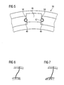
- FIG. 6 and FIG. 7 12 schematically show the torsion of the vane 20 by load and bearing action for a prior art fixed vane (FIG. FIG. 6 ) and for a fixed according to the invention guide vane ( FIG. 7 ).
- a head-side attached according to the prior art guide vane 20 is particularly strong, could at their weakest point, especially on the vane head 32, or on the inner ring particularly high loads and wear occur, which can lead to cracking and crack growth depending on the load.
- a resilient and thus designated as a floating bearing attachment of the guide vane head 30 is proposed, which leads to a much lower torsion of the vane 20 by load and bearing reaction.
- the load on the vane head 32 can be reduced, which delays or prevents the formation of cracks and wear.
- the displacement of the inner ring in the circumferential direction which occurs due to aerodynamic blade loading, causes a static load on the blade, which can be better compensated by the connection according to the invention than guide vanes fastened according to the prior art.
- the invention relates to a vane assembly 12 for an axial turbomachine comprising at least one annular vane support 14 and an inner ring 22 concentric with the vane support 14, between which a plurality of vanes 20 are radially disposed.
- a vane assembly 12 for an axial turbomachine comprising at least one annular vane support 14 and an inner ring 22 concentric with the vane support 14, between which a plurality of vanes 20 are radially disposed.
- the vane 20 on the inner ring 22nd are resiliently attached.
- the fastening takes place by means of a spring element 52.
- the spring element 52 By the spring element 52, a uniform contact pressure of the guide vane head 30 to the inner ring 22 or possibly to a further spring element 52 can be ensured, so that occurring stresses and wear can be reduced.
Abstract
Description
Die Erfindung betrifft eine Leitschaufelanordnung für eine Axialturbomaschine, umfassend einen ringförmigen Leitschaufelträger und einen konzentrisch zum Leitschaufelträger angeordneten Innenring, zwischen denen strahlenartig eine Anzahl von Leitschaufeln angeordnet ist, wobei jede Leitschaufel am Leitschaufelträger befestigt ist.The invention relates to a vane assembly for an axial turbomachine comprising an annular vane carrier and an inner ring disposed concentrically with the vane carrier, between which a plurality of vanes are radiantly arranged, each vane being attached to the vane carrier.
Eine eingangs genannte Leitschaufelanordnung ist hinreichend aus dem Stand der Technik bekannt. Beispielsweise ist diese bei Verdichtern von stationären Gasturbinen bekannt, bei denen Leitschaufeln des Verdichters an einen Leitschaufelträger oder an einem Verdichtergehäuse befestigt sind. Hierzu weisen bekannte Leitschaufelträger, welche im Speziellen zumeist rohrförmig ausgebildet sind, an ihren inneren Mantelflächen in Umfangsrichtung verlaufende Haltenuten mit Hinterschneidungen auf, in denen Leitschaufeln bzw. Außenringe eingeschoben und befestigt sind. Die Leitschaufeln können dabei einerseits als freistehende Leitschaufeln ausgebildet sein, so dass deren Schaufelblattspitzen unter Spaltbildung einer inneren Begrenzungswand des Strömungspfades des Verdichters gegenüberliegen. Auch ist bekannt, dass die innere Begrenzungswand des Strömungspfades Teil der Leitschaufeln ist oder von den Leitschaufeln selber gehalten werden kann. In diesem Fall weisen die bekannten Leitschaufeln entweder jeweils kopfseitig angeordnete Deckbänder auf, welche dann Teile der Begrenzungswand bilden, oder die Leitschaufeln tragen kopfseitig einen Innenring, dessen äußere Mantelfläche dann die innere Begrenzung für den Strömungspfad darstellt. Die Befestigung des Innenrings an den Leitschaufeln der Leitschaufelanordnung kann dabei über eine geeignete Verschraubung, durch Anschweißen oder auch mittels Verstemmens erfolgen.An initially mentioned vane arrangement is sufficiently known from the prior art. For example, this is known in compressors of stationary gas turbines, in which vanes of the compressor are attached to a vane support or on a compressor housing. For this purpose, known guide blade carrier, which are formed in particular in most cases tubular, on its inner circumferential surfaces in the circumferential direction extending retaining grooves with undercuts in which guide vanes or outer rings are inserted and secured. On the one hand, the guide vanes may be formed as free-standing vanes, so that their airfoil tips lie opposite one another with the gap forming an inner boundary wall of the flow path of the compressor. It is also known that the inner boundary wall of the flow path is part of the vanes or can be held by the vanes themselves. In this case, the known guide vanes either have cover bands arranged on the top side, which then form parts of the boundary wall, or the guide vanes carry an inner ring on the top side, the outer surface of which then represents the inner boundary for the flow path. The attachment of the inner ring to the guide vanes of the vane assembly can be done via a suitable screw, by welding or by caulking.
Bei den bekannten Befestigungsarten des Innenrings an den Leitschaufeln der Leitschaufelanordnung kann es während des Betriebs des Verdichters zu Verschleiß oder Risseinleitung an der Verbindung von Innenring und Leitschaufel kommen. Die Verschleißerscheinungen treten aufgrund der Verdrehung des Innenrings durch die aerodynamische Schaufellast auf und/oder aufgrund von thermisch bedingten Dehnungen, welche durch die bei der Verdichtung im Verdichter erzeugte Wärme auftritt. Auch periodische Schaufellaständerungen oder Vibrationen können zu Verschleißerscheinungen führen.In the known types of mounting of the inner ring on the vanes of the vane assembly, it may come during operation of the compressor to wear or crack initiation at the connection of inner ring and vane. The signs of wear occur due to the rotation of the inner ring by the aerodynamic load on the blade and / or due to thermally induced strains, which occurs due to the heat generated in the compression in the compressor. Periodic changes in the load on the blades or vibrations can also lead to signs of wear.
Aufgabe der Erfindung ist demzufolge die Bereitstellung einer eingangs genannten Leitschaufelanordnung für eine axiale Turbomaschine, die eine besonders dehnungstolerante, verschleißarme und zuverlässige Befestigung von Leitschaufeln an einem Innenring ermöglicht.The object of the invention is therefore to provide an aforementioned vane arrangement for an axial turbomachine, which allows a particularly strain-tolerant, low-wear and reliable attachment of vanes to an inner ring.
Die der Erfindung zugrunde liegende Aufgabe wird durch eine Leitschaufelanordnung gemäß den Merkmalen des Anspruchs 1 gelöst.The object underlying the invention is achieved by a vane arrangement according to the features of claim 1.
Erfindungsgemäß ist vorgesehen, dass bei der eingangs genannten Leitschaufelanordnung der Innenring der Leitschaufelanordnung federnd über zumindest eine der Leitschaufeln befestigt ist. Vorzugsweise sind alle Leitschaufeln der Leitschaufelanordnung federnd mit dem Innenring verbunden.According to the invention, it is provided that, in the case of the guide vane arrangement mentioned at the outset, the inner ring of the vane arrangement is fastened resiliently over at least one of the guide vanes. Preferably, all vanes of the vane assembly are resiliently connected to the inner ring.
Der Erfindung liegt die Erkenntnis zugrunde, dass eine starre Verbindung von Leitschaufeln am Innenring nachteilig ist. Sie schlägt demgemäß eine Verbindungsart vor, die im geringfügigen Umfang Relativbewegungen von Leitschaufeln zu Innenring verschleißfrei ermöglicht, ohne Beschädigung der Verbindung. Folglich wendet sich die Erfindung von den bisherigen Vorgehensweisen ab, bei dem eine starre, feste Verbindung zwischen Leitschaufeln und Innenring vorgesehen war.The invention is based on the finding that a rigid connection of guide vanes on the inner ring is disadvantageous. Accordingly, it proposes a type of connection which permits relative movements of guide vanes to inner ring without wear to a small extent, without damaging the connection. Consequently, the invention turns away from the previous approaches, in which a rigid, firm connection between vanes and inner ring was provided.
Im Zuge der Erfindung soll nun zur Fixierung der Leitschaufel am Innenring ein Federelement verwendet werden. Durch die Verwendung einer federnden Befestigung von Leitschaufeln am Innenring kann eine gleichmäßige Anpressung der betreffenden Leitschaufel am Innenring erfolgen, was auftretende Spannungen, verursacht durch thermische Dehnungen und/oder statische und/oder dynamische Spannungen wirkungsvoll minimiert. Gleichzeitig lassen sich durch die federnde Befestigung die für eine einfache Montage erforderlichen Montagespiele besonders einfach ausgleichen.In the course of the invention, a spring element is now to be used for fixing the guide vane on the inner ring. By using a resilient mounting of vanes on the inner ring a uniform contact pressure of the relevant vane on the inner ring can be done, which effectively minimizes occurring stresses caused by thermal expansion and / or static and / or dynamic stresses. At the same time can be easily compensated by the resilient attachment required for easy installation mounting games.
Durch die Verringerung von Verschleiß und Vermeidung von Rissen kann eine Erhöhung der Anlagenverfügbarkeit insgesamt ermöglicht werden, da bisher erforderliche Kontrollen und Nacharbeit verschlissener Komponenten bei Verwendung der Erfindung wegfallen. Weiterhin kann Reparaturaufwand gespart werden und ggf. auf Zwischeninspektionen verzichtet werden. Außerdem ist die beschriebene Maßnahme leicht kombinierbar mit einigen der aus dem Stand der Technik bekannten Lösungen, was eine verbesserte Reparaturmöglichkeit bestehender Turbomaschinen darstellt.By reducing wear and avoiding cracks, overall system uptime can be increased since previously required controls and rework of worn components are eliminated using the invention. Furthermore, repair costs can be saved and may be waived on intermediate inspections. In addition, the described measure can easily be combined with some of the solutions known from the prior art, which represents an improved repair possibility of existing turbomachines.
Vorteilhafte Ausgestaltungen sind in den Unteransprüchen angegeben.Advantageous embodiments are specified in the subclaims.
Gemäß einer vorteilhaften Weiterbildung der Erfindung umfasst jede betreffende Leitschaufel innenringseitig einen im Innenring versenkten Leitschaufelkopf, mittels dem die Leitschaufel am Innenring federnd befestigt ist. Damit die betreffende Leitschaufel am Innenring federnd befestigbar ist, umfasst sie mindestens ein Konstruktionselement, namentlich den Leitschaufelkopf, der mit dem Innenring verbindbar und geeignet ist, diesen zu tragen.According to an advantageous embodiment of the invention, each respective vane on the inner ring side comprises a sunk in the inner ring vane head, by means of which the vane is resiliently mounted on the inner ring. Thus, the relevant vane on the inner ring is resiliently fastened, it comprises at least one structural element, namely the vane head, which is connectable to the inner ring and adapted to carry this.
Nach einer weiteren vorteilhaften Ausgestaltung umfasst der Leitschaufelkopf jeder betreffenden Leitschaufel einen Steg, welcher jeweils in einer nach außen geöffneten, am Innenring angeordneten Aussparung angeordnet ist und bei dem in zumindest einer der dem betreffenden Steg zugewandten Seitenfläche der Aussparung ein Federelement angeordnet ist, welches am Innenring und am Steg der betreffenden Leitschaufel vorgespannt anliegt. Somit ist zur federnden Befestigung der Leitschaufel am Innenring ein weiteres Konstruktionsbauteil, das Federelement, vorgesehen, welches sich einerseits am Innenring abstützt und andererseits am Steg der betreffenden Leitschaufel. Dabei ist die Leitschaufelanordnung so ausgelegt, dass das Federelement vorgespannt ist und somit den Steg der betreffenden Leitschaufel entweder mittelbar oder unmittelbar an den Innenring, im Detail an eine der beiden Seitenflächen der Aussparung, anpresst.According to a further advantageous embodiment, the guide vane head of each relevant vane comprises a web, which is in each case arranged in an outwardly open, arranged on the inner ring recess and in which in at least one of the respective web facing side surface of the recess, a spring element is arranged, which bears against the inner ring and the web of the relevant vane biased. Thus, for the resilient attachment of the guide vane on the inner ring another construction component, the spring element, provided, which is supported on the one hand on the inner ring and on the other hand at the web of the relevant vane. In this case, the guide vane assembly is designed so that the spring element is biased and thus the web of the relevant vane either indirectly or directly to the inner ring, in detail to one of the two side surfaces of the recess pressed.
Vorteilhafterweise ist der Leitschaufelkopf mittels des Steges und eines sich daran quer erstreckenden Kopfteils hammerförmig ausgebildet, wobei der Steg das Kopfteil mit einem aerodynamisch gekrümmten Schaufelblatt der betreffenden Leitschaufel verbindet und wobei der Innenring eine zum Leitschaufelkopf korrespondierend geformte umlaufende Nut zur Aufnahme der Leitschaufelköpfe aufweist, welche Nut jeweils im Abschnitt zwischen zwei benachbarten Leitschaufeln von einer Abdeckung, also zum Schaufelblatt hin, verschlossen ist. Durch die formschlüssige Verbindung der Leitschaufel mit dem Innenring mittels des an der Leitschaufel angeordneten hammerförmigen Leitschaufelkopfes bzw. Leitschaufelhakens und einer am Innenring vorgesehenen Nut, welche korrespondierend zur Form des Leitschaufelkopfes ausgebildet ist, kann eine Leitschaufelanordnung angegeben werden, bei welcher der Innenring von den Leitschaufeln besonders zuverlässig getragen wird. Diese Ausgestaltung ist insbesondere dann von Vorteil, wenn die Leitschaufelanordnung selber, der Innenring und/oder der ringförmige Leitschaufelträger jeweils nicht einstückig ausgebildet ist, sondern durch zumindest zwei bogenförmige Ringsegmente gebildet werden, welche bei der Montage und/oder Demontage jeweils getrennt von den anderen Ringsegmenten gehandhabt werden. Die Abdeckung verhindert einerseits ein Verschieben des Innenrings gegenüber den Leitschaufeln entlang des Umfangs, da die Abdeckung jeweils zwischen zwei Leitschaufeln angeordnet ist und somit den Verschiebeweg entlang der Nut blockiert. Andererseits sorgt die Abdeckung auch für eine stufenlose Begrenzungsfläche des Strömungskanals.Advantageously, the guide vane head is hammer-shaped by means of the web and a head part extending transversely thereto, wherein the web connects the head part with an aerodynamically curved airfoil of the relevant vane and wherein the inner ring has a circumferential groove corresponding to the vane head for receiving the vane heads, which groove each in the section between two adjacent vanes of a cover, so the blade is closed. By the positive connection of the guide vane with the inner ring by means of the arranged on the vane hammer-shaped vane and a groove provided on the inner ring, which is formed corresponding to the shape of the vane head, a vane arrangement can be specified in which the inner ring of the vanes particularly is worn reliably. This embodiment is particularly advantageous when the vane assembly itself, the inner ring and / or the annular vane support is not formed integrally, but are formed by at least two arcuate ring segments, which in each case separate from the other ring segments during assembly and / or disassembly be handled. The cover prevents on the one hand a displacement of the inner ring relative to the Vanes along the circumference, since the cover is arranged between two vanes and thus blocks the displacement along the groove. On the other hand, the cover also provides for a stepless boundary surface of the flow channel.
Gemäß einer weiteren vorteilhaften Ausgestaltung sind zwei Federelemente für jede betreffende Leitschaufel vorgesehen, die an einander gegenüberliegenden Seitenflächen der Aussparung angeordnet sind. Hierdurch ist jede derartig gelagerte Leitschaufel mittelbar, also über die Federelemente, am Innenring vorgespannt angeordnet. Zweckmäßigerweise ist dabei die Federkraft jedes Federelements in Umfangsrichtung des Innenrings gerichtet. Sofern als Federelement eine Spannhülse verwendet wird, ist zwischen dem Steg jeder betreffenden Leitschaufel und der Spannhülse lediglich ein Linienkontakt vorhanden, wodurch die statische Belastung der Leitschaufel an der Verbindungsstelle geringer ist als bei einer flächig festgelegten Leitschaufel. Da die statische Belastung hauptsächlich durch eine auftretende Verschiebung des Innenrings in Umfangsrichtung verursacht durch eine aerodynamische Schaufelbelastung erfolgt, ist eine verschiebungstolerante Befestigung in Form einer federnden Lagerung in Umfangsrichtung erforderlich, um Verschleiß und Rissentstehung und Risswachstum zu vermeiden.According to a further advantageous embodiment, two spring elements are provided for each relevant vane, which are arranged on opposite side surfaces of the recess. As a result, each such mounted vane is indirectly, so arranged biased on the inner ring via the spring elements. Conveniently, the spring force of each spring element is directed in the circumferential direction of the inner ring. If a clamping sleeve is used as the spring element, only a line contact is present between the web of each relevant vane and the clamping sleeve, whereby the static load on the vane at the connection point is less than in a flat fixed guide vane. Since the static load is mainly due to an occurring displacement of the inner ring in the circumferential direction caused by an aerodynamic blade load, a displacement-tolerant mounting in the form of a resilient mounting in the circumferential direction is required to avoid wear and cracking and crack growth.
Zu einer einfachen Herstellung der Leitschaufelanordnung kann es von Vorteil sein, wenn der Innenring zwei Teilringe umfasst, die nach ihrem Zusammensetzen zu einem einstückigen Innenring montiert werden können.For a simple manufacture of the vane arrangement, it may be advantageous if the inner ring comprises two partial rings, which can be mounted after their assembly into a one-piece inner ring.
Sofern die Leitschaufelanordnung insbesondere in stationären Turbomaschinen verwendet wird, ist es von Vorteil, wenn die Leitschaufelanordnung selber zwei oder mehrere Ringsegmente umfasst, das heißt, dass der Innenring und/oder der ringförmige Leitschaufelträger als bogenförmige Ringsegmente ausgebildet sind. Da die Leitschaufelanordnung und deren Komponenten zu den drehfesten Bestandteilen einer Turbomaschine gehören, welche, sofern im stationären Bereich verwendet, eine Teilungsebene aufweisen, wodurch die drehfesten Bestandteile für eine obere und eine untere Hälfte geteilt sind, eignet sich eine in zwei, je 180° große Ringsegmente aufgeteilte Leitschaufelanordnung insbesondere für stationäre Turbomaschinen. Dann ist eine einfache Montage der einzelnen Bauteile zu einer insgesamt ringförmigen Leitschaufelanordnung möglich. Vorzugsweise wird die Leitschaufelanordnung in einer Turbomaschine verwendet, die insbesondere als Axialverdichter oder Axialturbine ausgebildet sein kann. Zudem kann der Leitschaufelträger innerhalb eines separaten Gehäuses angeordnet oder auch selber als Gehäuse ausgebildet sein.If the vane arrangement is used in particular in stationary turbomachines, it is advantageous if the vane arrangement itself comprises two or more ring segments, that is, that the inner ring and / or the annular vane carrier are formed as arcuate ring segments. Since the vane assembly and its components to the non-rotatable components of a Turbomachine, which, if used in the stationary area, have a dividing plane, whereby the rotationally fixed components are divided for an upper and a lower half, is suitable in two, each 180 ° large ring segments divided guide vane assembly, especially for stationary turbomachinery. Then, a simple assembly of the individual components to an overall annular vane arrangement is possible. Preferably, the guide vane assembly is used in a turbomachine, which may be designed in particular as an axial compressor or axial turbine. In addition, the guide blade carrier can be arranged within a separate housing or even be designed as a housing itself.
Die Erfindung wird anhand einer Zeichnung erläutert. Weitere Vorteile und weitere Merkmale ergeben sich dabei aus der Figurenbeschreibung.The invention will be explained with reference to a drawing. Further advantages and further features emerge from the description of the figures.
Es zeigen:
- FIG 1
- ein Segment 10 einer Leitschaufelanordnung 12 einer Axialturbomaschine in einer perspektivischen Darstellung;
- FIG 2
- eine Explosionsdarstellung von
FIG 1 ; - FIG 3
- einen Längsschnitt durch eine erfindungsgemäße Verbindung von Leitschaufel und Innenring;
- FIG 4
- einen Ausschnitt des Innenrings ohne Leitschaufel;
- FIG 5
- eine Seitenansicht gemäß dem Schnitt V-V und
- FIG 6, 7
- schematisch die Verwindung der Leitschaufel durch Last- und Auflagereaktion für eine nach dem Stand der Technik befestigte Leitschaufel und für eine nach der Erfindung befestigten Leitschaufel.
- FIG. 1
- a segment 10 of a vane assembly 12 of an axial turbomachine in a perspective view;
- FIG. 2
- an exploded view of
FIG. 1 ; - FIG. 3
- a longitudinal section through an inventive connection of the vane and inner ring;
- FIG. 4
- a section of the inner ring without a vane;
- FIG. 5
- a side view according to the section VV and
- FIG. 6, 7
- schematically the torsion of the vane by load and Auflagereaktion for a fixed according to the prior art vane and for a fixed according to the invention vane.
Die sich aus zwei Segmenten 10 zusammensetzende Leitschaufelanordnung 12 umfasst somit einen Ring von Leitschaufeln 20, welcher auch als Leitschaufelkranz bekannt ist und Teil einer Verdichterstufe oder Turbinenstufe sein kann.The vane assembly 12 composed of two segments 10 thus includes a ring of
Der Leitschaufelträger 14 ist an einem nicht weiter dargestellten Gehäuse der Axialturbomaschine, beispielsweise eines Verdichters, befestigt oder selbst als Gehäuse ausgebildet. Der Leitschaufelträger 14 trägt die an ihm innen befestigten Leitschaufeln 20, die ihrerseits innenkopfseitig den Innenring 22 tragen. Die äußere Mantelfläche des Innenrings 22 und die Innenfläche 16 des Leitschaufelträgers 14 bilden dabei die radiale innere und äußere Begrenzung für ein die Axialturbomaschine durchströmendes Medium. Sofern die Axialturbomaschine als Verdichter ausgebildet ist, handelt es sich bei dem Medium um verdichtete bzw. zu verdichtende Luft.The
Der Innenring 22 ist mit einer nach außen offenen Nut 44 versehen, deren Längsschnittkontur korrespondierend zum Leitschaufelkopf 30 ausgebildet ist. Der Innenring 22 umfasst die beiden Teilringe 36, 38, die ihrerseits gemäß
Ein Herausfallen des Federelementes 52 aus der Tasche 50 in die Aussparung 46 kann aufgrund der Lage der Tasche 50 vermieden werden. Dies erleichtert den Zusammenbau der Leitschaufelanordnung 12.Falling out of the
Selbstverständlich könnte das Federelement 52 auch in Taschen gelagert sein, welche am Steg 32, und nicht an den Seitenflächen 48 der Ansparung 46 angeordnet sind.Of course, the
Da eine kopfseitig nach dem Stand der Technik befestigte Leitschaufel 20 besonders stark verwunden wird, konnten an deren schwächsten Stelle, namentlich am Leitschaufelkopf 32, oder auch am Innenring besonders hohe Belastungen und Verschleiß auftreten, die je nach Belastung zu Rissentstehung und Risswachstum führen können. Mit der Erfindung wird nun eine federnde und somit als Loslager zu bezeichnende Befestigung des Leitschaufelkopfes 30 vorgeschlagen, die zu einer wesentlich geringeren Verwindung der Leitschaufel 20 durch Last- und Auflagereaktion führt. Hierdurch kann die Belastung am Leitschaufelkopf 32 verringert werden, was das Entstehen von Rissen und Verschleiß verzögert bzw. verhindert. Insbesondere die durch aerodynamische Schaufelbelastung auftretende Verschiebung des Innenrings in Umfangsrichtung verursacht eine statische Belastung der Schaufel, welche durch die erfindungsgemäße Verbindung besser kompensiert werden kann als nach dem Stand der Technik befestigte Leitschaufeln.Since a head-side attached according to the prior
Insgesamt betrifft die Erfindung eine Leitschaufelanordnung 12 für eine Axialturbomaschine, die zumindest einen ringförmigen Leitschaufelträger 14 und einen konzentrisch zum Leitschaufelträger 14 angeordneten Innenring 22 umfasst, zwischen denen strahlenartig eine Anzahl von Leitschaufeln 20 angeordnet sind. Um eine verschleißarme und besonders langlebige Befestigung der von dem Leitschaufelträger 14 getragenen Leitschaufel 20 am Innenring 22 anzugeben, wird vorgeschlagen, dass die Leitschaufel 20 am Innenring 22 federnd befestigt sind. Die Befestigung erfolgt dabei mittels eines Federelementes 52. Durch das Federelement 52 kann eine gleichmäßige Anpressung des Leitschaufelkopfes 30 an den Innenring 22 oder gegebenenfalls an ein weiteres Federelement 52 gewährleistet werden, so dass auftretende Spannungen sowie Verschleiß vermindert werden können.In general, the invention relates to a vane assembly 12 for an axial turbomachine comprising at least one
Claims (13)
wobei jede Leitschaufel am Leitschaufelträger (14) befestigt ist,
dadurch gekennzeichnet, dass
zumindest eine der Leitschaufeln (20) am Innenring (22) federnd befestigt ist.An airfoil assembly (12) for an axial turbomachine comprising an annular vane support (14) and an inner ring (22) concentric with the vane support (14), between which a plurality of vanes (20) are radially disposed,
wherein each vane is attached to the vane support (14),
characterized in that
at least one of the guide vanes (20) on the inner ring (22) is resiliently mounted.
bei dem jede betreffende Leitschaufel (20) innenringseitig einen im Innenring (22) versenkten Leitschaufelkopf (30) umfasst, mittels dem die Leitschaufel (20) am Innenring (22) federnd befestigt ist.Guide vane assembly (12) according to claim 1,
in which each relevant vane (20) on the inner ring side comprises a guide vane head (30) sunk in the inner ring (22), by means of which the vane (20) is resiliently fastened to the inner ring (22).
bei dem der Leitschaufelkopf (30) jeder betreffenden Leitschaufel (20) einen Steg (32) umfasst, welcher jeweils in einer nach außen geöffneten, am Innenring (22) angeordneten Aussparung (46) angeordnet ist, und
bei dem in zumindest einer der dem betreffenden Steg (32) zugewandten Seitenfläche (48) der Aussparung (46) ein Federelement (52) angeordnet ist, welches am Innenring (22) und am Steg (32) der betreffenden Leitschaufel (20) vorgespannt anliegt.Guide vane assembly (12) according to claim 2,
in which the vane head (30) of each relevant vane (20) comprises a web (32) which is arranged in each case in a recess (46) which is open towards the outside and which is arranged on the inner ring (22), and
wherein in at least one of the respective web (32) facing side surface (48) of the recess (46) a spring element (52) is arranged, which on the inner ring (22) and the web (32) of the respective vane (20) biased ,
bei dem der Leitschaufelkopf (30) mittels des Steges (32) und eines sich daran quer erstreckenden Kopfteils (34) hammerförmig ausgebildet ist und der Steg (32) das Kopfteil (34) mit einem aerodynamisch gekrümmten Schaufelblatt (28) der betreffenden Leitschaufel (20) verbindet und
bei dem der Innenring (22) eine zum Leitschaufelkopf (30) korrespondierend geformte umlaufende Nut (44) zur Aufnahme der Leitschaufelköpfe (30) aufweist, welche Nut (44) jeweils im Abschnitt zwischen zwei benachbarten Leitschaufeln (20) von einer Abdeckung (47) verschlossen ist.Guide vane assembly (12) according to claim 3,
in which the vane head (30) is hammer-shaped by means of the web (32) and a head part (34) extending transversely thereto, and the web (32) has the head part (34) with an aerodynamically curved airfoil (28) of the relevant vane (20 ) connects and
in which the inner ring (22) has a circumferential groove (44) corresponding to the vane head (30) for receiving the vane heads (30), which groove (44) in each case in the section between two adjacent vanes (20) of a cover (47). is closed.
bei dem für jede betreffende Leitschaufel (20) zwei Federelemente (52) vorgesehen sind, die an einander gegenüberliegenden Seitenflächen (48) der Aussparung (46) angeordnet sind.Guide vane assembly (12) according to any one of claims 1 to 4,
in that two spring elements (52) are provided for each relevant vane (20), which are arranged on opposite side surfaces (48) of the recess (46).
bei dem das Federelement (52) als Spannhülse ausgebildet ist.Guide vane assembly (12) according to any one of claims 3 to 5,
in which the spring element (52) is designed as a clamping sleeve.
bei der in den Seitenflächen (48) eine Tasche (50) zur Aufnahme des Federelements (52) vorgesehen ist, aus der das Federelement (52) teilweise herausragt.Guide vane assembly (12) according to any one of claims 3 to 6,
in which in the side surfaces (48) a pocket (50) for receiving the spring element (52) is provided, from which the spring element (52) protrudes partially.
bei dem die Federkraft in Umfangsrichtung des Innenrings (22) gerichtet ist.Guide vane assembly (12) according to one of claims 1 to 7,
in which the spring force in the circumferential direction of the inner ring (22) is directed.
bei dem der Innenring (22) zwei Teilringe (36, 38) umfasst.Guide vane assembly (12) according to any one of claims 1 to 8,
in which the inner ring (22) comprises two partial rings (36, 38).
bei dem der Innenring (22) und/oder der ringförmige Leitschaufelträger (14) zumindest zwei Ringsegmente umfassen.Guide vane assembly (12) according to any one of claims 1 to 9,
wherein the inner ring (22) and / or the annular vane support (14) comprise at least two ring segments.
bei dem der Leitschaufelträger (14) als ein Gehäuse ausgebildet ist.Guide vane arrangement according to one of claims 1 to 10,
wherein the vane support (14) is formed as a housing.
ausgebildet als Axialverdichter oder Axialturbine.Turbomachine according to claim 12,
designed as axial compressor or axial turbine.
Priority Applications (7)
| Application Number | Priority Date | Filing Date | Title |
|---|---|---|---|
| EP08021215A EP2194230A1 (en) | 2008-12-05 | 2008-12-05 | Guide blade assembly for an axial turbo engine |
| PCT/EP2009/064427 WO2010063525A1 (en) | 2008-12-05 | 2009-11-02 | Guide blade arrangement for an axial turbo-machine |
| US13/132,339 US20110286851A1 (en) | 2008-12-05 | 2009-11-02 | Guide blade arrangement for an axial turbo-machine |
| CN2009801488378A CN102239311A (en) | 2008-12-05 | 2009-11-02 | Guide blade arrangement for an axial turbo-machine |
| RU2011127398/06A RU2011127398A (en) | 2008-12-05 | 2009-11-02 | GUIDE BLADE SYSTEM FOR AXIAL TURBINE MACHINE |
| EP09747819A EP2356319A1 (en) | 2008-12-05 | 2009-11-02 | Guide blade arrangement for an axial turbo-machine |
| JP2011537913A JP2012510582A (en) | 2008-12-05 | 2009-11-02 | Guide vane array structure for axial turbomachinery |
Applications Claiming Priority (1)
| Application Number | Priority Date | Filing Date | Title |
|---|---|---|---|
| EP08021215A EP2194230A1 (en) | 2008-12-05 | 2008-12-05 | Guide blade assembly for an axial turbo engine |
Publications (1)
| Publication Number | Publication Date |
|---|---|
| EP2194230A1 true EP2194230A1 (en) | 2010-06-09 |
Family
ID=40591884
Family Applications (2)
| Application Number | Title | Priority Date | Filing Date |
|---|---|---|---|
| EP08021215A Withdrawn EP2194230A1 (en) | 2008-12-05 | 2008-12-05 | Guide blade assembly for an axial turbo engine |
| EP09747819A Withdrawn EP2356319A1 (en) | 2008-12-05 | 2009-11-02 | Guide blade arrangement for an axial turbo-machine |
Family Applications After (1)
| Application Number | Title | Priority Date | Filing Date |
|---|---|---|---|
| EP09747819A Withdrawn EP2356319A1 (en) | 2008-12-05 | 2009-11-02 | Guide blade arrangement for an axial turbo-machine |
Country Status (6)
| Country | Link |
|---|---|
| US (1) | US20110286851A1 (en) |
| EP (2) | EP2194230A1 (en) |
| JP (1) | JP2012510582A (en) |
| CN (1) | CN102239311A (en) |
| RU (1) | RU2011127398A (en) |
| WO (1) | WO2010063525A1 (en) |
Cited By (2)
| Publication number | Priority date | Publication date | Assignee | Title |
|---|---|---|---|---|
| CH704000A1 (en) * | 2010-10-26 | 2012-04-30 | Alstom Technology Ltd | Guide vane arrangement of axial-flow compressor, has guide vanes formed like leaf spring such that transient phases of operation due to thermal influences are compensated by elastic deformation of guide vanes |
| EP3075961A1 (en) * | 2015-04-02 | 2016-10-05 | Siemens Aktiengesellschaft | Guide vane assembly |
Families Citing this family (7)
| Publication number | Priority date | Publication date | Assignee | Title |
|---|---|---|---|---|
| TWI537477B (en) | 2013-07-25 | 2016-06-11 | 華碩電腦股份有限公司 | Fan blade structure and centrifugal blower using the same |
| EP3169878A1 (en) * | 2014-07-18 | 2017-05-24 | Siemens Energy, Inc. | Turbine assembly with detachable struts |
| EP3284919A1 (en) * | 2016-08-16 | 2018-02-21 | General Electric Technology GmbH | Axial flow turbine having a diaphragm split in two halves at a joint plane |
| CN106988794B (en) * | 2017-06-02 | 2018-12-14 | 中国航发南方工业有限公司 | Stator sub-assembly clamping means and stator sub-assembly |
| US11028709B2 (en) * | 2018-09-18 | 2021-06-08 | General Electric Company | Airfoil shroud assembly using tenon with externally threaded stud and nut |
| DE102020200073A1 (en) * | 2020-01-07 | 2021-07-08 | Siemens Aktiengesellschaft | Guide vane ring |
| US11236615B1 (en) * | 2020-09-01 | 2022-02-01 | Solar Turbines Incorporated | Stator assembly for compressor mid-plane rotor balancing and sealing in gas turbine engine |
Citations (8)
| Publication number | Priority date | Publication date | Assignee | Title |
|---|---|---|---|---|
| US2872156A (en) * | 1956-08-20 | 1959-02-03 | United Aircraft Corp | Vane retaining device |
| US2914300A (en) * | 1955-12-22 | 1959-11-24 | Gen Electric | Nozzle vane support for turbines |
| EP1076159A2 (en) * | 1999-08-09 | 2001-02-14 | United Technologies Corporation | Stator vane blank and method of forming the vane blank |
| EP1111246A1 (en) * | 1999-12-21 | 2001-06-27 | Techspace Aero S.A. | Stiffened annular part |
| GB2400415A (en) * | 2003-04-11 | 2004-10-13 | Rolls Royce Plc | A vane mounting |
| EP1762703A2 (en) * | 2005-09-12 | 2007-03-14 | Pratt & Whitney Canada Corp. | Foreign object damage resistant vane assembly |
| US20070177973A1 (en) * | 2006-01-27 | 2007-08-02 | Mitsubishi Heavy Industries, Ltd | Stationary blade ring of axial compressor |
| EP1908923A1 (en) * | 2006-09-26 | 2008-04-09 | Snecma | Device for fixing a stator vane in an annular casing of a turbomachine, jet engine including the device and method of installing the stator vane |
Family Cites Families (13)
| Publication number | Priority date | Publication date | Assignee | Title |
|---|---|---|---|---|
| GB133862A (en) * | 1900-01-01 | |||
| US1010750A (en) * | 1909-04-28 | 1911-12-05 | Colonial Trust Co | Turbine-balde shroud. |
| US1298564A (en) * | 1918-06-12 | 1919-03-25 | Gen Electric | Elastic-fluid turbine. |
| DE461307C (en) * | 1925-08-07 | 1928-06-16 | Siemens Schuckertwerke Akt Ges | Intermediate floor for steam turbines |
| GB660383A (en) * | 1949-02-23 | 1951-11-07 | Winnett Boyd | Blade mounting for axial-flow compressors and the like |
| US2894318A (en) * | 1952-10-08 | 1959-07-14 | Gen Electric | Turbomachine bucket-wheel fabricated by casting |
| US3367630A (en) * | 1967-01-16 | 1968-02-06 | Westinghouse Electric Corp | Continuous shroud structure |
| US3836281A (en) * | 1973-03-02 | 1974-09-17 | Carrier Corp | Nozzle structure for steam turbines |
| GB2084261A (en) * | 1980-09-30 | 1982-04-07 | Rolls Royce | Mounting compressor stator blades |
| JPS613903U (en) * | 1984-06-15 | 1986-01-11 | 株式会社日立製作所 | gas turbine nozzle |
| GB8922339D0 (en) * | 1989-10-04 | 1989-11-22 | Rolls Royce Plc | Improvements in or relating to labyrinth seal structures |
| JPH0494402A (en) * | 1990-08-09 | 1992-03-26 | Mitsubishi Heavy Ind Ltd | Manufacture of nozzle for axial flow turbine |
| US6543995B1 (en) * | 1999-08-09 | 2003-04-08 | United Technologies Corporation | Stator vane and stator assembly for a rotary machine |
-
2008
- 2008-12-05 EP EP08021215A patent/EP2194230A1/en not_active Withdrawn
-
2009
- 2009-11-02 EP EP09747819A patent/EP2356319A1/en not_active Withdrawn
- 2009-11-02 JP JP2011537913A patent/JP2012510582A/en active Pending
- 2009-11-02 CN CN2009801488378A patent/CN102239311A/en active Pending
- 2009-11-02 WO PCT/EP2009/064427 patent/WO2010063525A1/en active Application Filing
- 2009-11-02 RU RU2011127398/06A patent/RU2011127398A/en not_active Application Discontinuation
- 2009-11-02 US US13/132,339 patent/US20110286851A1/en not_active Abandoned
Patent Citations (8)
| Publication number | Priority date | Publication date | Assignee | Title |
|---|---|---|---|---|
| US2914300A (en) * | 1955-12-22 | 1959-11-24 | Gen Electric | Nozzle vane support for turbines |
| US2872156A (en) * | 1956-08-20 | 1959-02-03 | United Aircraft Corp | Vane retaining device |
| EP1076159A2 (en) * | 1999-08-09 | 2001-02-14 | United Technologies Corporation | Stator vane blank and method of forming the vane blank |
| EP1111246A1 (en) * | 1999-12-21 | 2001-06-27 | Techspace Aero S.A. | Stiffened annular part |
| GB2400415A (en) * | 2003-04-11 | 2004-10-13 | Rolls Royce Plc | A vane mounting |
| EP1762703A2 (en) * | 2005-09-12 | 2007-03-14 | Pratt & Whitney Canada Corp. | Foreign object damage resistant vane assembly |
| US20070177973A1 (en) * | 2006-01-27 | 2007-08-02 | Mitsubishi Heavy Industries, Ltd | Stationary blade ring of axial compressor |
| EP1908923A1 (en) * | 2006-09-26 | 2008-04-09 | Snecma | Device for fixing a stator vane in an annular casing of a turbomachine, jet engine including the device and method of installing the stator vane |
Cited By (3)
| Publication number | Priority date | Publication date | Assignee | Title |
|---|---|---|---|---|
| CH704000A1 (en) * | 2010-10-26 | 2012-04-30 | Alstom Technology Ltd | Guide vane arrangement of axial-flow compressor, has guide vanes formed like leaf spring such that transient phases of operation due to thermal influences are compensated by elastic deformation of guide vanes |
| EP3075961A1 (en) * | 2015-04-02 | 2016-10-05 | Siemens Aktiengesellschaft | Guide vane assembly |
| WO2016156211A1 (en) | 2015-04-02 | 2016-10-06 | Siemens Aktiengesellschaft | Guide vane assembly |
Also Published As
| Publication number | Publication date |
|---|---|
| CN102239311A (en) | 2011-11-09 |
| RU2011127398A (en) | 2013-01-10 |
| JP2012510582A (en) | 2012-05-10 |
| EP2356319A1 (en) | 2011-08-17 |
| US20110286851A1 (en) | 2011-11-24 |
| WO2010063525A1 (en) | 2010-06-10 |
Similar Documents
| Publication | Publication Date | Title |
|---|---|---|
| EP2194230A1 (en) | Guide blade assembly for an axial turbo engine | |
| DE10210866C1 (en) | Guide blade segment fixing device for flow channel of aircraft gas turbine uses slot and hook fixing and pin fitting through latter | |
| EP2696041B1 (en) | Guide blade assembly of a gas turbine and assembly method | |
| EP2399004B1 (en) | Rotor section for a rotor of a turbo machine, rotor blade for a turbo machine and blocking element | |
| CH703872B1 (en) | Fixing bolts for a variable vane. | |
| EP1922471A1 (en) | Arrangement for axially securing rotating blades in a rotor and use | |
| EP2918913B1 (en) | Combustion chamber of a gas turbine | |
| EP2463484A1 (en) | Tubular casing for a turbo engine | |
| EP3152407A2 (en) | Vane ring, inner ring, and turbomachine | |
| EP2173972B1 (en) | Rotor for an axial flow turbomachine | |
| DE102008010294A1 (en) | Gas turbine combustor with ceramic flame tube | |
| EP2591213B1 (en) | Compressor and corresponding gas turbine | |
| EP3287608B1 (en) | Internal ring for a guide- blade rim of a turbomachine | |
| CH698921B1 (en) | Turbo engine i.e. gas turbine, has sealing element arranged transverse to gap and engaging recesses of blades, and radial outer wall and/or radial inner wall of recesses running transverse to gap | |
| EP3379037B1 (en) | Seal on the inner ring of a guide blade assembly | |
| EP2394028B1 (en) | Sealing apparatus at the blade shaft of a rotor stage of an axial turbomachine and the use thereof | |
| EP2310634B1 (en) | Rotating blade system for a row of rotating blades of a turbomachine | |
| EP3176386B1 (en) | Inner shroud assembly, corresponding inner shroud, inner casing and turbomachine | |
| DE102016201766A1 (en) | Guide vane system for a turbomachine | |
| WO2011088819A2 (en) | Housing system for an axial turbomachine | |
| DE102008020732A1 (en) | Charging device i.e. exhaust gas turbo charger, for motor vehicle, has fixing units movably supported/guided at shovel bearing ring, at bearing housing or at contour sleeve in radial direction | |
| WO2007031408A1 (en) | Cover strip comprising a detachable anchoring for a row of blades of a turbomachine | |
| EP2881545B1 (en) | Sealing element, sealing device and gas turbine engine | |
| EP2993305B1 (en) | Gas turbine | |
| EP2455587B1 (en) | Rotor for a turbomachine, corrresponding turbomachine and method for manufacturing, repairing or upgrading |
Legal Events
| Date | Code | Title | Description |
|---|---|---|---|
| PUAI | Public reference made under article 153(3) epc to a published international application that has entered the european phase |
Free format text: ORIGINAL CODE: 0009012 |
|
| AK | Designated contracting states |
Kind code of ref document: A1 Designated state(s): AT BE BG CH CY CZ DE DK EE ES FI FR GB GR HR HU IE IS IT LI LT LU LV MC MT NL NO PL PT RO SE SI SK TR |
|
| AX | Request for extension of the european patent |
Extension state: AL BA MK RS |
|
| AKY | No designation fees paid | ||
| STAA | Information on the status of an ep patent application or granted ep patent |
Free format text: STATUS: THE APPLICATION IS DEEMED TO BE WITHDRAWN |
|
| 18D | Application deemed to be withdrawn |
Effective date: 20101210 |