DE102018008564B4 - Device and method for assisting positioning of a vehicle - Google Patents
Device and method for assisting positioning of a vehicle Download PDFInfo
- Publication number
- DE102018008564B4 DE102018008564B4 DE102018008564.4A DE102018008564A DE102018008564B4 DE 102018008564 B4 DE102018008564 B4 DE 102018008564B4 DE 102018008564 A DE102018008564 A DE 102018008564A DE 102018008564 B4 DE102018008564 B4 DE 102018008564B4
- Authority
- DE
- Germany
- Prior art keywords
- vehicle
- unit
- light signal
- light
- charging
- Prior art date
- Legal status (The legal status is an assumption and is not a legal conclusion. Google has not performed a legal analysis and makes no representation as to the accuracy of the status listed.)
- Active
Links
Images


Classifications
-
- B—PERFORMING OPERATIONS; TRANSPORTING
- B60—VEHICLES IN GENERAL
- B60Q—ARRANGEMENT OF SIGNALLING OR LIGHTING DEVICES, THE MOUNTING OR SUPPORTING THEREOF OR CIRCUITS THEREFOR, FOR VEHICLES IN GENERAL
- B60Q9/00—Arrangement or adaptation of signal devices not provided for in one of main groups B60Q1/00 - B60Q7/00, e.g. haptic signalling
- B60Q9/002—Arrangement or adaptation of signal devices not provided for in one of main groups B60Q1/00 - B60Q7/00, e.g. haptic signalling for parking purposes, e.g. for warning the driver that his vehicle has contacted or is about to contact an obstacle
- B60Q9/004—Arrangement or adaptation of signal devices not provided for in one of main groups B60Q1/00 - B60Q7/00, e.g. haptic signalling for parking purposes, e.g. for warning the driver that his vehicle has contacted or is about to contact an obstacle using wave sensors
- B60Q9/005—Arrangement or adaptation of signal devices not provided for in one of main groups B60Q1/00 - B60Q7/00, e.g. haptic signalling for parking purposes, e.g. for warning the driver that his vehicle has contacted or is about to contact an obstacle using wave sensors using a video camera
-
- B—PERFORMING OPERATIONS; TRANSPORTING
- B60—VEHICLES IN GENERAL
- B60Q—ARRANGEMENT OF SIGNALLING OR LIGHTING DEVICES, THE MOUNTING OR SUPPORTING THEREOF OR CIRCUITS THEREFOR, FOR VEHICLES IN GENERAL
- B60Q1/00—Arrangement of optical signalling or lighting devices, the mounting or supporting thereof or circuits therefor
- B60Q1/26—Arrangement of optical signalling or lighting devices, the mounting or supporting thereof or circuits therefor the devices being primarily intended to indicate the vehicle, or parts thereof, or to give signals, to other traffic
- B60Q1/50—Arrangement of optical signalling or lighting devices, the mounting or supporting thereof or circuits therefor the devices being primarily intended to indicate the vehicle, or parts thereof, or to give signals, to other traffic for indicating other intentions or conditions, e.g. request for waiting or overtaking
- B60Q1/507—Arrangement of optical signalling or lighting devices, the mounting or supporting thereof or circuits therefor the devices being primarily intended to indicate the vehicle, or parts thereof, or to give signals, to other traffic for indicating other intentions or conditions, e.g. request for waiting or overtaking specific to autonomous vehicles
-
- B—PERFORMING OPERATIONS; TRANSPORTING
- B60—VEHICLES IN GENERAL
- B60Q—ARRANGEMENT OF SIGNALLING OR LIGHTING DEVICES, THE MOUNTING OR SUPPORTING THEREOF OR CIRCUITS THEREFOR, FOR VEHICLES IN GENERAL
- B60Q2400/00—Special features or arrangements of exterior signal lamps for vehicles
- B60Q2400/50—Projected symbol or information, e.g. onto the road or car body
Landscapes
- Engineering & Computer Science (AREA)
- Transportation (AREA)
- Mechanical Engineering (AREA)
- Automation & Control Theory (AREA)
- Multimedia (AREA)
- Radar, Positioning & Navigation (AREA)
- Remote Sensing (AREA)
- Human Computer Interaction (AREA)
- Charge And Discharge Circuits For Batteries Or The Like (AREA)
Abstract
Vorrichtung zur Unterstützung einer Positionierung eines Fahrzeugs (1) relativ zu einer fahrzeugexternen Ladeeinheit (2) zum Laden eines elektrischen Energiespeichers des Fahrzeugs (1) mit
- zumindest einer fahrzeugeigenen Kamera zur Erfassung einer Fahrzeugumgebung,
- zumindest einer fahrzeugeigenen Anzeigeeinheit zur Ausgabe eines mittels der zumindest einen Kamera erfassten Bilds (B),
- zumindest einer Lichteinheit zur Emission eines eine Position der Ladeeinheit (2) kennzeichnenden Lichtsignals (S),
- zumindest einer Fahrzeugdetektionseinheit zur Detektion einer Annäherung des Fahrzeugs (1) an die Ladeeinheit (2), wobei die Fahrzeugdetektionseinheit bei Detektion einer Annäherung des Fahrzeugs (1) ein Signal zur Aktivierung der Lichteinheit (2) ausgibt, und
die Kamera das Lichtsignal (S) erfasst,
dadurch gekennzeichnet, dass
eine Datenverarbeitungseinheit das Lichtsignal (S) und eine einer Form des Lichtsignals (S) entsprechende Kontrollmarkierung (M) in das Bild (B) projiziert, wobei die Kontrollmarkierung (M) bei Überdeckung mit dem Lichtsignal (S) ein Erreichen einer Sollposition des Fahrzeugs (1) relativ zur Ladeeinheit (2) darstellt.
- at least one vehicle-mounted camera for recording the vehicle's surroundings,
- at least one vehicle-specific display unit for outputting an image (B) captured by the at least one camera,
- at least one light unit for emitting a light signal (S) indicating a position of the loading unit (2),
- at least one vehicle detection unit for detecting an approach of the vehicle (1) to the charging unit (2), wherein the vehicle detection unit outputs a signal for activating the light unit (2) upon detection of an approach of the vehicle (1), and
the camera detects the light signal (S),
characterized in that
a data processing unit projects the light signal (S) and a control marking (M) corresponding to a shape of the light signal (S) into the image (B), wherein the control marking (M), when overlapping with the light signal (S), represents the reaching of a target position of the vehicle (1) relative to the loading unit (2).
Description
Die Erfindung betrifft eine Vorrichtung zur Unterstützung einer Positionierung eines Fahrzeugs gemäß dem Oberbegriff des Anspruchs 1.The invention relates to a device for supporting positioning of a vehicle according to the preamble of claim 1.
Die Erfindung betrifft weiterhin ein Verfahren zur Unterstützung einer Positionierung eines Fahrzeugs gemäß dem Oberbegriff des Anspruchs 6.The invention further relates to a method for supporting positioning of a vehicle according to the preamble of claim 6.
Aus der
Weiterhin ist aus der
Ferner beschreibt die
- - einer ersten fahrzeugseitigen Antenne zum Abstrahlen eines ersten Lokalisierungssignals von einer ersten Position am Fahrzeug,
- - einer zweiten fahrzeugseitigen Antenne zum Abstrahlen eines zweiten Lokalisierungssignals von einer zur ersten Position unterschiedlichen zweiten Position am Fahrzeug,
- - einer fahrzeugseitigen Empfangseinrichtung zum Empfangen eines Antwortsignals eines bezüglich des Fahrzeugs externen Transceivers, das Informationen bezüglich der ersten Empfangsfeldstärke des ersten Lokalisierungssignals und der zweiten Empfangsfeldstärke des zweiten Lokalisierungssignals jeweils am Ort des externen Transceivers umfasst,
- - einer fahrzeugseitigen Auswerteeinrichtung zum Ermitteln der relativen Position des Fahrzeugs zum externen Transceiver anhand der ersten und zweiten Empfangsfeldstärke,
- - einer fahrzeugseitigen Ausgabeeinrichtung zum Ausgeben von mit dem Fahrzeug auszuführenden Lenkbefehlen und Fahrbefehlen, um aus den von der ermittelten relativen Position eine mit dem externen Transceiver verbundene Zielposition zu erreichen.
- - a first vehicle-side antenna for emitting a first localization signal from a first position on the vehicle,
- - a second vehicle-side antenna for emitting a second localization signal from a second position on the vehicle that is different from the first position,
- - a vehicle-side receiving device for receiving a response signal from a transceiver external to the vehicle, which comprises information regarding the first reception field strength of the first localization signal and the second reception field strength of the second localization signal, each at the location of the external transceiver,
- - a vehicle-side evaluation device for determining the relative position of the vehicle to the external transceiver based on the first and second reception field strength,
- - a vehicle-side output device for outputting steering commands and driving commands to be executed by the vehicle in order to reach a target position connected to the external transceiver from the determined relative position.
Aus der
- - Empfangen von Bild-Daten von einer Kamera des Fahrzeugs, wobei die Kamera eingerichtet ist, eine Umgebung des Fahrzeugs zu erfassen;
- - Detektieren der fahrzeugexternen Primärspule in der erfassten Umgebung des Fahrzeugs auf Basis der empfangenen Bild-Daten; und
- - Bereitstellen von Informationen bezüglich der detektierten Primärspule für die Positionierung der Sekundärspule relativ zu der Primärspule.
- - Receiving image data from a camera of the vehicle, wherein the camera is configured to capture an environment of the vehicle;
- - Detecting the vehicle-external primary coil in the detected environment of the vehicle based on the received image data; and
- - Providing information regarding the detected primary coil for positioning the secondary coil relative to the primary coil.
Dabei wird eine bildliche Darstellung der Umgebung des Fahrzeugs mit der detektieren Primärspule generiert; wobei in der bildlichen Darstellung die detektierte Primärspule gegenüber der Umgebung des Fahrzeugs graphisch hervorgehoben ist. Die bildliche Darstellung wird auf einem Bildschirm des Fahrzeugs als Top-View Ansicht des Fahrzeugs ausgegeben.A visual representation of the surroundings of the vehicle with the detected primary coil is generated; in the visual representation, the detected primary coil is graphically highlighted compared to the surroundings of the vehicle. The visual representation is displayed on a screen in the vehicle as a top view of the vehicle.
Die gattungsbildende Schrift
Der Erfindung liegt die Aufgabe zu Grunde, eine verbesserte Vorrichtung und ein verbessertes Verfahren zur Unterstützung einer Positionierung eines Fahrzeugs relativ zu einer fahrzeugexternen Ladeeinheit zum Laden eines elektrischen Energiespeichers des Fahrzeugs anzugeben.The invention is based on the object of specifying an improved device and an improved method for supporting positioning of a vehicle relative to a vehicle-external charging unit for charging an electrical energy storage device of the vehicle.
Hinsichtlich der Vorrichtung wird die Aufgabe erfindungsgemäß durch die im Anspruch 1 angegebenen Merkmale und hinsichtlich des Verfahrens durch die im Anspruch 6 angegebenen Merkmale gelöst.With regard to the device, the object is achieved according to the invention by the features specified in claim 1 and with regard to the method by the features specified in claim 6.
Die Vorrichtung zur Unterstützung einer Positionierung eines Fahrzeugs relativ zu einer fahrzeugexternen Ladeeinheit zum Laden eines elektrischen Energiespeichers des Fahrzeugs umfasst zumindest eine fahrzeugeigene Kamera zur Erfassung einer Fahrzeugumgebung und zumindest eine fahrzeugeigene Anzeigeeinheit zur Ausgabe eines mittels der zumindest einen Kamera erfassten Bilds.The device for supporting positioning of a vehicle relative to a vehicle-external charging unit for charging an electrical energy storage device of the vehicle comprises at least one vehicle-specific camera for capturing a vehicle environment and at least one vehicle-specific display unit for outputting an image captured by means of the at least one camera.
Erfindungsgemäß umfasst die Vorrichtung zumindest eine Lichteinheit zur Emission eines eine Position der Primärspule kennzeichnenden Lichtsignals und zumindest eine Fahrzeugdetektionseinheit zur Detektion einer Annäherung des Fahrzeugs an die Primärspule, wobei die Fahrzeugdetektionseinheit bei Detektion einer Annäherung des Fahrzeugs ein Signal zur Aktivierung der Lichteinheit ausgibt, die Kamera das Lichtsignal in dem Bild erfasst oder eine Datenverarbeitungseinheit das Lichtsignal in das Bild projiziert.According to the invention, the device comprises at least one light unit for emitting a light signal characterizing a position of the primary coil and at least one vehicle detection unit for detecting an approach of the vehicle to the primary coil, wherein the vehicle detection unit outputs a signal for activating the light unit upon detection of an approach of the vehicle, the camera captures the light signal in the image or a data processing unit projects the light signal into the image.
Hierbei wird gemäß der Erfindung eine einer Form des Lichtsignals entsprechende Kontrollmarkierung mit in das Bild projiziert, wobei die Kontrollmarkierung bei Überdeckung mit dem Lichtsignal ein Erreichen einer Sollposition des Fahrzeugs relativ zur Ladeeinheit darstellt.According to the invention, a control marking corresponding to a shape of the light signal is projected into the image, wherein the control marking, when overlapped by the light signal, represents the reaching of a target position of the vehicle relative to the loading unit.
Die Vorrichtung zeichnet sich dabei durch eine besonders hohe Robustheit aus und ermöglicht mit visueller Unterstützung eine einfache und zielgenaue manuelle oder automatische Positionierung des Fahrzeugs zu der Ladeeinheit mit geringer oder keiner Abweichung zu einer Sollposition, so dass ein einfaches und für einen Nutzer komfortables konduktives oder induktives Laden des Energiespeichers mit hohem Wirkungsgrad möglich ist. Auch wird ein automatisiertes Laden, insbesondere mit autonomer Anfahrt des Fahrzeugs an die Ladeeinheit, ermöglicht. Dabei ist die Vorrichtung mit geringem Material- und Kostenaufwand realisierbar.The device is characterized by its particularly high level of robustness and, with visual support, enables simple and precise manual or automatic positioning of the vehicle to the charging unit with little or no deviation from a target position, so that simple and comfortable conductive or inductive charging of the energy storage device with high efficiency is possible for the user. Automated charging is also possible, in particular with the vehicle driving autonomously to the charging unit. The device can be implemented with little material and cost expenditure.
Vorteilhafte Ausgestaltungen der Erfindung sind Gegenstand der Unteransprüche.Advantageous embodiments of the invention are the subject of the subclaims.
Ausführungsbeispiele der Erfindung werden im Folgenden anhand von Zeichnungen näher erläutert.Embodiments of the invention are explained in more detail below with reference to drawings.
Dabei zeigen:
-
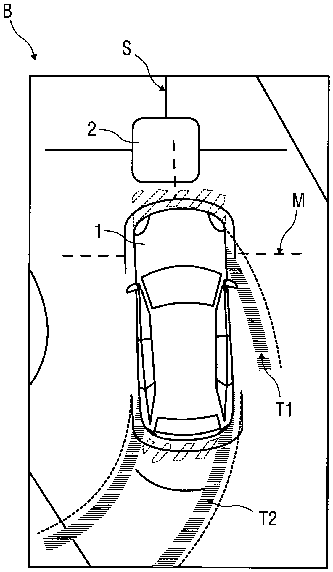
1 schematisch ein Bild eines Fahrzeugs, einer Fahrzeugumgebung und einer Ladeeinheit aus einer Vogelperspektive, -
2 schematisch die Ladeeinheit gemäß1 und ein eine Position der Ladeeinheit kennzeichnendes Lichtsignal, -
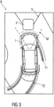
3 schematisch ein weiteres Bild eines Fahrzeugs, einer Fahrzeugumgebung und einer Ladeeinheit aus einer Vogelperspektive und -
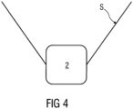
4 schematisch die Ladeeinheit gemäß3 und ein eine Position der Ladeeinheit kennzeichnendes Lichtsignal.
-
1 schematically a picture of a vehicle, a vehicle environment and a loading unit from a bird's eye view, -
2 schematically the loading unit according to1 and a light signal indicating a position of the loading unit, -
3 schematically another image of a vehicle, a vehicle environment and a loading unit from a bird's eye view and -
4 schematically the loading unit according to3 and a light signal indicating a position of the loading unit.
Einander entsprechende Teile sind in allen Figuren mit den gleichen Bezugszeichen versehen.Corresponding parts are provided with the same reference numerals in all figures.
In
Das Bild B wird anhand von Einzelbildern mehrerer nicht näher dargestellter fahrzeugeigener Kameras oder anhand eines Einzelbildes einer ebenfalls nicht näher dargestellten fahrzeugeigenen Kamera erzeugt und wird mittels einer beispielsweise im Fahrzeuginnenraum angeordneten nicht näher dargestellten Anzeigeeinheit ausgegeben. Die Ausgabe erfolgt beispielsweise zur Unterstützung eines Fahrers des Fahrzeugs 1 beim Rangieren oder Parken, wobei dem Bild B mit einem aktuellen Lenkeinschlag korrespondierende Trajektorien T1, T2 von Vorderrädern und Hinterrädern des Fahrzeugs 1 überlagert dargestellt sind.The image B is generated using individual images from several on-board cameras (not shown in detail) or from an individual image from an on-board camera (also not shown in detail) and is output using a display unit (not shown in detail) arranged in the vehicle interior, for example. The output is used, for example, to support a driver of the vehicle 1 when maneuvering or parking, with trajectories T1, T2 of the front wheels and rear wheels of the vehicle 1 corresponding to a current steering angle being shown superimposed on the image B.
Das Fahrzeug 1 ist ein Elektro- oder Hybridfahrzeug und umfasst zumindest einen nicht näher dargestellten Energiespeicher zur Speicherung elektrischer Energie zum Betrieb zumindest einer ebenfalls nicht näher dargestellten elektrischen Antriebseinheit des Fahrzeugs 1.The vehicle 1 is an electric or hybrid vehicle and comprises at least one energy storage device (not shown in detail) for storing electrical energy for operating at least one electric drive unit (also not shown in detail) of the vehicle 1.
Zu einem induktiven oder konduktiven Aufladen des Energiespeichers ist eine genaue Positionierung des Fahrzeugs 1 relativ zu einer Ladeeinheit 2 erforderlich. Im dargestellten Ausführungsbeispiel ist die Ladeeinheit 2 zu einer induktiven Ladung ausgebildet und umfasst eine nicht näher dargestellte, in eine vor dem Fahrzeug befindliche Bodenfläche integrierte oder auf dieser befindliche Primärspule. Das Fahrzeug 1 umfasst eine nicht näher dargestellte Sekundärspule, welche zur Energieübertragung zur Erzielung eines hohen Wirkungsgrads mit geringer Positionstoleranz oberhalb der Primärspule positioniert werden muss.For inductive or conductive charging of the energy storage device, an exact position ization of the vehicle 1 relative to a
Zur Unterstützung einer manuell vom Fahrer durchgeführten oder einer automatisiert durchgeführten Positionierung des Fahrzeugs 1 relativ zu der fahrzeugexternen Ladeeinheit 2 umfasst das Fahrzeug 1 zumindest eine nicht näher dargestellte fahrzeugeigene Kamera zur Erfassung einer Fahrzeugumgebung. Die Kamera ist beispielsweise am Unterboden des Fahrzeugs 1 angeordnet und in Längsrichtung des Fahrzeugs 1 nach vorn ausgerichtet. Es sind jedoch auch andere geeignete Positionen der Kamera am Fahrzeug 1 möglich. Auch ist es möglich, dass die Kamera Bestandteil eines Systems zur Erzeugung des Bilds B aus der Vogelperspektive ist.To support manual positioning by the driver or automated positioning of the vehicle 1 relative to the vehicle-
Weiterhin ist in nicht näher dargestellter Weise zumindest eine Lichteinheit zur Emission eines eine Position der Ladeeinheit 2 kennzeichnenden Lichtsignals S vorgesehen, wobei die Lichteinheit beispielsweise Bestandteil der Ladeeinheit 2 ist. Im dargestellten Ausführungsbeispiel umfasst die Lichteinheit zumindest eine Licht-Projektionseinheit zur Projektion des Lichtsignals S auf die Bodenfläche, wobei das Lichtsignal S im dargestellten Ausführungsbeispiel als so genanntes Fadenkreuz ausgebildet ist. Die Lichteinheit emittiert das Lichtsignal S im sichtbaren Wellenlängenbereich und/oder einem Infrarot-Wellenlängenbereich, wobei ein ausgesendetes Lichtspektrum und eine Form des Lichtsignals S von der Kamera erfassbar sind. Alternativ oder zusätzlich umfasst die Lichteinheit zumindest einen Lichtreflektor zur Erzeugung des Lichtsignals S mittels Reflexion, zumindest eine Lumineszenzeinheit zur Erzeugung des Lichtsignals S mittels Lumineszenz und/oder zumindest eine Fluoreszenzeinheit zur Erzeugung des Lichtsignals S mittels Fluoreszenz.Furthermore, in a manner not shown in more detail, at least one light unit is provided for emitting a light signal S identifying a position of the charging
Auch kann alternativ oder zusätzlich zu der Projektion des Lichtsignals S auf die Bodenfläche auch zumindest eine Lichtquelle selbst erfasst werden, wobei die Lichtquelle beispielsweise als Lichtleiste oder Lichtpunkt in die Ladeeinheit 2 und/oder in eine diese umgebende Bodenfläche integriert ist und Licht im sichtbaren Wellenlängenbereich und/oder einem Infrarot-Wellenlängenbereich emittiert.Alternatively or in addition to the projection of the light signal S onto the floor surface, at least one light source itself can also be detected, wherein the light source is integrated, for example, as a light bar or light point into the charging
Zu einer automatischen Aktivierung der Lichteinheit bei Annäherung des Fahrzeugs 1 an die Ladeeinheit 2 ist zumindest eine nicht näher dargestellte Fahrzeugdetektionseinheit zur Detektion der Annäherung des Fahrzeugs vorgesehen. Die Fahrzeugdetektionseinheit ist beispielsweise als ein in die Ladeeinheit 2 integrierter oder in deren Umgebung befindlicher Annäherungsdetektor ausgebildet, welcher auf beliebige Art und Weise ein sich näherndes Fahrzeug 1 erkennt. Die Erkennung der Annäherung kann dabei mittels einer Lichtschranke und/oder mittels anderer Sensoren, beispielsweise Infrarotsensoren, Lasersensoren, Radarsensoren und/oder eine Kamera erfolgen. Auch kann die Fahrzeugdetektionseinheit durch eine Kommunikation des Fahrzeugs 1 mit der Ladeeinheit 2, beispielsweise durch Aussenden eines entsprechenden Funksignals durch das Fahrzeug 1 bei Annäherung, erfolgen.For automatic activation of the light unit when the vehicle 1 approaches the
Nach der Aktivierung erfasst und erkennt die Kamera, aus deren Einzelbild das Bild B erzeugt wird, das Lichtsignal S, so dass bei einem Lichtsignal S im sichtbaren Wellenlängenbereich dieses mittels der Kamera ebenfalls erfasst und gemeinsam mit dem Bild B erfasst wird. Hierbei kann sich eine Form des Lichtsignals S auf vorgegebene „standardisierte“ Formen beschränken, die fahrzeugseitig hinterlegt sind oder es findet fahrzeugseitig eine allgemeine Formenerkennung des Lichtsignals S statt, die dann entsprechend auf die Position der Ladeeinheit 2 am Fahrzeug 1 umgerechnet und im Bild B dargestellt wird. Bei der Detektion des Fahrzeugs 1 über die Kommunikation mit der Ladeeinheit 2 kann die Form des verwendeten Lichtsignals S zwischen dem Fahrzeug 1 und der Ladeeinheit 2 kommuniziert werden, so dass die Möglichkeit besteht, dass die Ladeeinheit 2 Lichtsignale S mit unterschiedlichen Formen erzeugt und eine entsprechende Form auswählt, welche beispielsweise für ein Fahrzeug 1 eines bestimmten Typs vorteilhaft ist, indem eine Erkennung bei einer solchen Form einfacher und/oder zuverlässiger durchführbar ist.After activation, the camera, from whose individual image the image B is generated, captures and recognizes the light signal S, so that if a light signal S is in the visible wavelength range, this is also captured by the camera and captured together with the image B. In this case, a form of the light signal S can be limited to predetermined "standardized" forms that are stored on the vehicle side, or a general shape recognition of the light signal S takes place on the vehicle side, which is then converted accordingly to the position of the charging
Alternativ erfolgt die Erfassung des Lichtsignals S mittels zumindest einer weiteren fahrzeugeigenen Kamera, wobei in diesem Fall das Bild B mit dem erfassten Lichtsignal S überlagert wird, insbesondere, indem eine nicht gezeigte Datenverarbeitungseinheit das Lichtsignal S in das Bild B projiziert.Alternatively, the light signal S is detected by means of at least one further vehicle-mounted camera, in which case the image B is superimposed with the detected light signal S, in particular by a data processing unit (not shown) projecting the light signal S into the image B.
Erfindungsgemäß projiziert die Datenverarbeitungseinheit eine der Form des Lichtsignals S entsprechende Kontrollmarkierung M in das Bild B, welche bei Überdeckung mit dem Lichtsignal S ein Erreichen einer Sollposition des Fahrzeugs 1 relativ zur Ladeeinheit 2 darstellt.According to the invention, the data processing unit projects a control marking M corresponding to the shape of the light signal S into the image B, which control marking M, when overlapped by the light signal S, represents the reaching of a target position of the vehicle 1 relative to the
Somit kann der Fahrer das Fahrzeug 1 manuell derart steuern, dass das Lichtsignal S und die Kontrollmarkierung M auf dem Bild B in Überdeckung gelangen. Alternativ kann die Steuerung des Fahrzeugs 1 in einer zumindest teilautonomen Fahrt zumindest teilautomatisiert erfolgen.Thus, the driver can manually control the vehicle 1 in such a way that the light signal S and the control mark M on the image B are in alignment. Alternatively, the control of the vehicle 1 in an at least partially autonomous journey can be at least partially automated.
Dabei ist es möglich, dass aus einem Abstand und einer relativen Lage zwischen dem Lichtsignal S und der Kontrollmarkierung M Fahrrichtungsanweisungen und/oder Fahrbefehle ermittelt werden, welche dem Fahrer zusätzlich oder allein angezeigt werden oder in einer zumindest teilautomatisiert durchgeführten Fahrt direkt vom Fahrzeug 1 umgesetzt werden.It is possible that, from a distance and a relative position between the light signal S and the control marking M, driving direction instructions and/or driving commands are determined, which are displayed to the driver additionally or alone or are implemented directly by the vehicle 1 in an at least partially automated journey.
In einer nicht näher dargestellten Ausgestaltung erfolgt die Darstellung des Lichtsignals S und der Ladeeinheit 2 in einem anderen Bild B, welches beispielsweise von einer Frontkamera des Fahrzeugs 1 erfasst wurde. Hierzu erfolgt eine entsprechende Umrechnung der Position und einer Erstreckung des Lichtsignals S auf die entsprechende Perspektive der Frontkamera. Somit ist auch eine Realisierung bei Fahrzeugen 1, welche kein Kamerasystem zur Erzeugung von Bildern B aus der Vogelperspektive umfassen, möglich.In an embodiment not shown in detail, the light signal S and the
Um eine Beschädigung der Ladeeinheit 2, der Lichteinheit und gegebenenfalls Komponenten der Fahrzeugdetektionseinheit bei einem Überfahren derselben mit dem Fahrzeug 1 zu vermeiden, sind diese entsprechend überfahrbar ausgebildet.In order to avoid damage to the
In
Im Unterschied zu den Darstellungen in den
In nicht näher dargestellten Ausführungsbeispielen sind auch andere beliebig geformte, wie beispielsweise kreuzförmige oder T-kreuzförmige, Lichtsignale S und Kontrollmarkierungen M möglich.In embodiments not shown in detail, other arbitrarily shaped light signals S and control markings M, such as cross-shaped or T-cross-shaped, are also possible.
BezugszeichenlisteList of reference symbols
- 11
- Fahrzeugvehicle
- 22
- Ladeeinheit loading unit
- BB
- BildPicture
- MM
- Kontrollmarkierungcontrol marking
- SS
- Lichtsignaltraffic light
- T1T1
- Trajektorietrajectory
- T2T2
- Trajektorietrajectory
Claims (6)
Priority Applications (1)
| Application Number | Priority Date | Filing Date | Title |
|---|---|---|---|
| DE102018008564.4A DE102018008564B4 (en) | 2018-10-30 | 2018-10-30 | Device and method for assisting positioning of a vehicle |
Applications Claiming Priority (1)
| Application Number | Priority Date | Filing Date | Title |
|---|---|---|---|
| DE102018008564.4A DE102018008564B4 (en) | 2018-10-30 | 2018-10-30 | Device and method for assisting positioning of a vehicle |
Publications (2)
| Publication Number | Publication Date |
|---|---|
| DE102018008564A1 DE102018008564A1 (en) | 2019-04-11 |
| DE102018008564B4 true DE102018008564B4 (en) | 2024-10-02 |
Family
ID=65817011
Family Applications (1)
| Application Number | Title | Priority Date | Filing Date |
|---|---|---|---|
| DE102018008564.4A Active DE102018008564B4 (en) | 2018-10-30 | 2018-10-30 | Device and method for assisting positioning of a vehicle |
Country Status (1)
| Country | Link |
|---|---|
| DE (1) | DE102018008564B4 (en) |
Families Citing this family (2)
| Publication number | Priority date | Publication date | Assignee | Title |
|---|---|---|---|---|
| EP4032066B1 (en) | 2019-09-19 | 2025-04-02 | Continental Autonomous Mobility US, LLC | Automatic trailer camera calibration |
| EP3795410B1 (en) * | 2019-09-20 | 2022-03-02 | Continental Automotive GmbH | Method and apparatus for displaying ego-vehicle surroundings within an ego-vehicle with support of electrical charging |
Citations (5)
| Publication number | Priority date | Publication date | Assignee | Title |
|---|---|---|---|---|
| DE102013207907A1 (en) | 2013-04-30 | 2014-10-30 | Bayerische Motoren Werke Aktiengesellschaft | Vehicle positioning for inductive charging with the help of a vehicle camera |
| DE102014201821A1 (en) | 2014-02-03 | 2015-08-06 | Continental Automotive Gmbh | Charging device with positioning aid |
| DE102015013204A1 (en) | 2015-10-09 | 2016-03-31 | Daimler Ag | Method for positioning a vehicle for an inductive charging and charging station |
| DE102015208622A1 (en) | 2015-05-08 | 2016-11-10 | Continental Automotive Gmbh | A control device for assisting the guidance of a vehicle |
| DE102016015458A1 (en) | 2016-12-22 | 2017-08-10 | Daimler Ag | Device and method for inductively charging an electrical energy storage device of a vehicle |
-
2018
- 2018-10-30 DE DE102018008564.4A patent/DE102018008564B4/en active Active
Patent Citations (5)
| Publication number | Priority date | Publication date | Assignee | Title |
|---|---|---|---|---|
| DE102013207907A1 (en) | 2013-04-30 | 2014-10-30 | Bayerische Motoren Werke Aktiengesellschaft | Vehicle positioning for inductive charging with the help of a vehicle camera |
| DE102014201821A1 (en) | 2014-02-03 | 2015-08-06 | Continental Automotive Gmbh | Charging device with positioning aid |
| DE102015208622A1 (en) | 2015-05-08 | 2016-11-10 | Continental Automotive Gmbh | A control device for assisting the guidance of a vehicle |
| DE102015013204A1 (en) | 2015-10-09 | 2016-03-31 | Daimler Ag | Method for positioning a vehicle for an inductive charging and charging station |
| DE102016015458A1 (en) | 2016-12-22 | 2017-08-10 | Daimler Ag | Device and method for inductively charging an electrical energy storage device of a vehicle |
Also Published As
| Publication number | Publication date |
|---|---|
| DE102018008564A1 (en) | 2019-04-11 |
Similar Documents
| Publication | Publication Date | Title |
|---|---|---|
| DE102015218410B4 (en) | Method and device for determining the absolute position of a vehicle | |
| DE102013207906A1 (en) | Guided vehicle positioning for inductive charging with the help of a vehicle camera | |
| DE102012220052A1 (en) | Method for assisting driver of vehicle with returning maneuvers, involves determining starting position by detecting mark attached to outside of vehicle | |
| DE102014204872B4 (en) | A method and display system for displaying environmental information of a vehicle | |
| DE102017212221A1 (en) | Remote control method for a driver assistance system, driver assistance system and thus provided motor vehicle | |
| DE102019129193A1 (en) | APPLICATION OF AUXILIARY LIGHTING IN AN AUTOMATIC CLUTCH PROCESS | |
| DE102013207907B4 (en) | Vehicle positioning for inductive charging using a vehicle camera | |
| DE102018210340B4 (en) | Method and system for determining a relative pose between a target object and a vehicle | |
| DE102019123125A1 (en) | SYSTEM AND METHOD FOR REVERSE BRAKING DURING AUTOMATIC CLUTCH ORIENTATION | |
| DE102017223098A1 (en) | Method and device for determining a relative angle between two vehicles | |
| DE102018202526B4 (en) | Method for operating a driver assistance device of a motor vehicle by means of a navigation target device, control device, navigation target device, and motor vehicle | |
| DE102018221186B4 (en) | Autonomous parking procedures | |
| DE102018008564B4 (en) | Device and method for assisting positioning of a vehicle | |
| DE102016122990A1 (en) | Method for the autonomous maneuvering of a motor vehicle on a parking area with determination of a position deviation, infrastructure device, driver assistance systems, motor vehicle and communication system | |
| DE102016211227A1 (en) | Method and vehicle control system for generating images of an environment model and corresponding vehicle | |
| DE102017216127A1 (en) | Method for providing a communication connection between a stationary electrical charging station and a motor vehicle and control device and charging system | |
| DE102017111931A1 (en) | Method for monitoring a ground area below a motor vehicle by means of an optical sensor device, sensor device, driver assistance system and motor vehicle | |
| DE102019120599A1 (en) | SYSTEM AND METHOD FOR ADJUSTING THE TRAILER | |
| DE102014219876A1 (en) | Method and device for supporting an automatic parking process of a motor vehicle | |
| DE102013217718A1 (en) | Charging station for inductive energy transfer and method for positioning an inductive energy transfer device | |
| DE102017102640A1 (en) | A method for detecting a charging device for inductively charging an energy storage device of a motor vehicle by means of a camera of the motor vehicle, computing device, vehicle assistance system and motor vehicle | |
| DE102020202334A1 (en) | Method for positioning a vehicle, control device for a vehicle, vehicle, method for supporting the positioning of a vehicle, inductive charging station or control device | |
| DE102017218191B3 (en) | Parking assistance for parking on an oncoming lane | |
| DE102016013180A1 (en) | Method for positioning a motor vehicle relative to an inductive charging device | |
| WO2020074186A1 (en) | Inductive charging system and positioning method |
Legal Events
| Date | Code | Title | Description |
|---|---|---|---|
| R230 | Request for early publication | ||
| R012 | Request for examination validly filed | ||
| R081 | Change of applicant/patentee |
Owner name: MERCEDES-BENZ GROUP AG, DE Free format text: FORMER OWNER: DAIMLER AG, 70327 STUTTGART, DE Owner name: DAIMLER AG, DE Free format text: FORMER OWNER: DAIMLER AG, 70327 STUTTGART, DE |
|
| R081 | Change of applicant/patentee |
Owner name: MERCEDES-BENZ GROUP AG, DE Free format text: FORMER OWNER: DAIMLER AG, STUTTGART, DE |
|
| R016 | Response to examination communication | ||
| R018 | Grant decision by examination section/examining division | ||
| R020 | Patent grant now final |