DE102016005299A1 - Method for producing a curved tubular connecting element - Google Patents

Method for producing a curved tubular connecting element Download PDF

Info

Publication number
DE102016005299A1
DE102016005299A1 DE102016005299.6A DE102016005299A DE102016005299A1 DE 102016005299 A1 DE102016005299 A1 DE 102016005299A1 DE 102016005299 A DE102016005299 A DE 102016005299A DE 102016005299 A1 DE102016005299 A1 DE 102016005299A1
Authority
DE
Germany
Prior art keywords
pipe section
connection
geometries
pipe
connecting element
Prior art date
Legal status (The legal status is an assumption and is not a legal conclusion. Google has not performed a legal analysis and makes no representation as to the accuracy of the status listed.)
Pending
Application number
DE102016005299.6A
Other languages
German (de)
Inventor
Bernhard Müller
Current Assignee (The listed assignees may be inaccurate. Google has not performed a legal analysis and makes no representation or warranty as to the accuracy of the list.)
Eisele GmbH
Original Assignee
Eisele Pneumatics GmbH and Co KG
Priority date (The priority date is an assumption and is not a legal conclusion. Google has not performed a legal analysis and makes no representation as to the accuracy of the date listed.)
Filing date
Publication date
Application filed by Eisele Pneumatics GmbH and Co KG filed Critical Eisele Pneumatics GmbH and Co KG
Priority to DE102016005299.6A priority Critical patent/DE102016005299A1/en
Priority to MX2018013350A priority patent/MX2018013350A/en
Priority to US16/097,651 priority patent/US11103965B2/en
Priority to PCT/EP2017/000383 priority patent/WO2017190823A1/en
Priority to EP17714640.4A priority patent/EP3452236A1/en
Priority to CA3022649A priority patent/CA3022649A1/en
Priority to CN201780033154.2A priority patent/CN109414743A/en
Priority to JP2018558350A priority patent/JP2019514696A/en
Publication of DE102016005299A1 publication Critical patent/DE102016005299A1/en
Pending legal-status Critical Current

Links

Images

Classifications

    • BPERFORMING OPERATIONS; TRANSPORTING
    • B23MACHINE TOOLS; METAL-WORKING NOT OTHERWISE PROVIDED FOR
    • B23PMETAL-WORKING NOT OTHERWISE PROVIDED FOR; COMBINED OPERATIONS; UNIVERSAL MACHINE TOOLS
    • B23P15/00Making specific metal objects by operations not covered by a single other subclass or a group in this subclass
    • BPERFORMING OPERATIONS; TRANSPORTING
    • B21MECHANICAL METAL-WORKING WITHOUT ESSENTIALLY REMOVING MATERIAL; PUNCHING METAL
    • B21DWORKING OR PROCESSING OF SHEET METAL OR METAL TUBES, RODS OR PROFILES WITHOUT ESSENTIALLY REMOVING MATERIAL; PUNCHING METAL
    • B21D7/00Bending rods, profiles, or tubes
    • B21D7/02Bending rods, profiles, or tubes over a stationary forming member; by use of a swinging forming member or abutment
    • FMECHANICAL ENGINEERING; LIGHTING; HEATING; WEAPONS; BLASTING
    • F16ENGINEERING ELEMENTS AND UNITS; GENERAL MEASURES FOR PRODUCING AND MAINTAINING EFFECTIVE FUNCTIONING OF MACHINES OR INSTALLATIONS; THERMAL INSULATION IN GENERAL
    • F16LPIPES; JOINTS OR FITTINGS FOR PIPES; SUPPORTS FOR PIPES, CABLES OR PROTECTIVE TUBING; MEANS FOR THERMAL INSULATION IN GENERAL
    • F16L37/00Couplings of the quick-acting type
    • F16L37/08Couplings of the quick-acting type in which the connection between abutting or axially overlapping ends is maintained by locking members
    • F16L37/084Couplings of the quick-acting type in which the connection between abutting or axially overlapping ends is maintained by locking members combined with automatic locking
    • F16L37/091Couplings of the quick-acting type in which the connection between abutting or axially overlapping ends is maintained by locking members combined with automatic locking by means of a ring provided with teeth or fingers
    • FMECHANICAL ENGINEERING; LIGHTING; HEATING; WEAPONS; BLASTING
    • F16ENGINEERING ELEMENTS AND UNITS; GENERAL MEASURES FOR PRODUCING AND MAINTAINING EFFECTIVE FUNCTIONING OF MACHINES OR INSTALLATIONS; THERMAL INSULATION IN GENERAL
    • F16LPIPES; JOINTS OR FITTINGS FOR PIPES; SUPPORTS FOR PIPES, CABLES OR PROTECTIVE TUBING; MEANS FOR THERMAL INSULATION IN GENERAL
    • F16L43/00Bends; Siphons
    • F16L43/001Bends; Siphons made of metal

Landscapes

  • Engineering & Computer Science (AREA)
  • Mechanical Engineering (AREA)
  • Branch Pipes, Bends, And The Like (AREA)
  • Bending Of Plates, Rods, And Pipes (AREA)
  • Lining Or Joining Of Plastics Or The Like (AREA)
  • Turning (AREA)

Abstract

Die Erfindung betrifft ein Verfahren zum Herstellen eines gebogenen rohrförmigen Verbindungselementes mit zumindest den folgenden Herstellschritten:
– Durchführen einer spanenden Bearbeitung für ein metallisches, geradlinig verlaufendes Rohrstück (10) vorgebbarer Länge unter Einbezug von Anschlussgeometrien (12, 14) für die Aufnahme von separaten Anschlussteilen (18, 20), die dem Anschließen einer medienführenden Verrohrung dienen,
– Durchführen eines Biegevorganges für das derart spanend erstellte Rohrstück (10) mit einem vorgebbaren Biegeradius, vorzugsweise von bis zu 90 Grad, und
– Anbringen des jeweiligen Anschlussteils (18, 20) an der zuordenbaren endseitigen Anschlussgeometrie (12, 14) des Rohrstückes (10).
The invention relates to a method for producing a bent tubular connecting element with at least the following manufacturing steps:
- Carrying out a machining for a metallic, rectilinear pipe section (10) of predeterminable length with inclusion of connection geometries (12, 14) for receiving separate connection parts (18, 20), which serve to connect a media-carrying piping,
- Performing a bending process for the thus produced machined pipe section (10) with a predetermined bending radius, preferably of up to 90 degrees, and
- Attaching the respective connection part (18, 20) to the assignable end-side connection geometry (12, 14) of the pipe section (10).

Figure DE102016005299A1_0001

Description

Die Erfindung betrifft ein Verfahren zum Herstellen eines gebogenen rohrförmigen Verbindungselementes.The invention relates to a method for producing a bent tubular connecting element.

Durch die DE 10 2007 016 766 A1 ist eine Vorrichtung zum Spritzgießen von Rohrkrümmern bekannt, die einen Krümmerabschnitt mit einer kreisbogenförmigen Mittellinie und gleichbleibendem Innenquerschnitt und beidseitig daran anschließenden zylindrischen Anschlussstutzen aufweisen, mit einer mehrteiligen Spritzgießform aus Außenformteilen und Kernteilen bestehenden Dauerform, die in der Ebene der kreisbogenförmigen Mittellinie des Krümmerabschnitts in zumindest zwei Außenformteile teilbar ist, die einen Formhohlraum bilden, und die zumindest drei bewegliche Kernteile umfasst.By the DE 10 2007 016 766 A1 a device for injection molding of elbows is known, having a manifold portion with a circular arc-shaped center line and constant inner cross-section and both sides adjoining cylindrical connecting piece, with a multi-part injection mold of outer moldings and core parts existing permanent form, in the plane of the circular arc-shaped center line of the elbow portion in at least two Partial mold parts is divisible, which form a mold cavity, and which comprises at least three movable core parts.

Nachteilig bei dem dahingehenden Stand der Technik ist, dass für jede herzustellende Form eines Rohrkrümmers und für jeden Biegeradius des Rohrkrümmers eine eigenständige Spritzgießform zu erstellen ist, was entsprechend kostenintensiv ist und mit einem hohen Herstellaufwand einhergeht.A disadvantage of the pertinent prior art is that for each mold to be produced of a pipe bend and for each bending radius of the elbow a separate injection mold is to create, which is correspondingly expensive and is accompanied by a high manufacturing cost.

Durch die DE 27 14 782 A1 ist ein Verfahren zur Herstellung von Rohrkrümmern bekannt, insbesondere aus dünnwandigem Material bestehend, wobei ein gerades Rohrstück über einer Streckeinrichtung derart streckgedrückt wird, dass die Ausgangswandstärke des Rohrstückes über den Rohrumfang unterschiedlich reduziert wird, wobei das gerade Rohrstück durch die unterschiedliche Materialabstreckung in einen Rohrkrümmer verformt wird, dessen neutrale Faser, in der die Ausgangswandstärke erhalten bleibt, im inneren Rohrbogen liegt.By the DE 27 14 782 A1 a method for the production of elbows is known, in particular consisting of thin-walled material, wherein a straight piece of pipe stretched over a stretching device is such that the output wall thickness of the pipe section is reduced differently over the pipe circumference, wherein the straight piece of pipe deformed by the different material extension into a pipe bend whose neutral fiber, in which the initial wall thickness is maintained, lies in the inner pipe bend.

Bei der bekannten Lösung kommen weichgelötete, hartgelötete oder geschweißte, gepunktete, gefalzte sowie nahtlos gezogene Rohrstücke für den eigentlichen Biegevorgang zur Anwendung, wobei je nach angestrebter Bogenform Dehnungen bis 180% und Wandstärkenreduzierungen von bis zu 60% des eingesetzten Materials für den Rohrkrümmer auftreten. Aufgrund der zumindest teilweisen Reduzierung der Ausgangswandstärke des zunächst geradlinig verlaufenden Rohrstückes beim Biegevorgang kommt es insgesamt zu einer Schwächung des Eintragmaterials mit der Folge, dass die dahingehende Lösung für Hochdruckanwendungen wenig geeignet ist.In the known solution weichgelötete, brazed or welded, dotted, folded and seamless drawn pipe sections for the actual bending process are used, depending on the desired arc shape strains up to 180% and wall thickness reductions of up to 60% of the material used for the elbow occur. Due to the at least partial reduction of the output wall thickness of the initially rectilinear pipe section during the bending process, there is a total weakening of the entry material with the result that the pertinent solution is less suitable for high-pressure applications.

Ausgehend von diesem Stand der Technik liegt daher der Erfindung die Aufgabe zugrunde, derart ein Verfahren zur Verfügung zu stellen, dass bei geringen Herstellkosten und vermindertem Herstellaufwand ein gebogenes rohrförmiges Verbindungselement erhalten wird, das auch für Hochdruckanwendungen geeignet ist.Based on this prior art, the invention is therefore an object of the invention to provide such a method that at low production costs and reduced manufacturing costs, a bent tubular connecting element is obtained, which is also suitable for high pressure applications.

Eine dahingehende Aufgabe löst ein Verfahren mit den Merkmalen des Patentanspruchs 1 in seiner Gesamtheit.This object is achieved by a method having the features of patent claim 1 in its entirety.

Dadurch dass bei dem erfindungsgemäßen Verfahren die folgenden Herstellschritte vorgesehen sind:

  • – Durchführen einer spanenden Bearbeitung für ein metallisches, geradlinig verlaufendes Rohrstück vorgebbarer Länge unter Einbezug von Anschlussgeometrien für die Aufnahme von separaten Anschlussteilen, die dem Anschließen einer medienführenden Verrohrung dienen,
  • – Durchführen eines Biegevorganges für das derart spanend erstellte Rohrstück mit einem vorgebbaren Biegeradius, vorzugsweise von bis zu 90 Grad, und
  • – Anbringen des jeweiligen Anschlussteils an der zuordenbaren endseitigen Anschlussgeometrie des Rohrstückes vorzugsweise mittels Bördeln, Pressen, Schweißen, Schrauben oder Klippen,
ist mit geringem Kosten- und Herstellaufwand ein druckbeständiger Rohrkrümmer oder Biegerohr als Verbindungselement im Rahmen einer Anschluss-Verrohrung erhalten. Dadurch dass im Ausgangszustand ein geradlinig verlaufendes Rohrstück mit seinen Anschlussgeometrien spanend, insbesondere im Rahmen einer Drehbearbeitung erhalten wird, ist eine gleichbleibende Rohr-Wandstärke im interessierenden Verbindungsbereich mit den Anschlussteilen erhalten und zwar im Wesentlichen auch nach dem Biegevorgang, so dass sich dergestalt durch die spanende Bearbeitung des Rohrstückes relativ dünne Wandstärken auch im Bereich der Anschlussgeometrien realisieren lassen, die dennoch ausreichen, um Hochdruckanwendungen für das Verbindungsstück zu ermöglichen.Due to the fact that the following production steps are provided in the method according to the invention:
  • - Carrying out a machining operation for a metallic, rectilinear pipe section of predefinable length, including connection geometries for receiving separate connection parts, which serve to connect a media-carrying piping,
  • - Performing a bending process for the thus produced machined pipe section with a predetermined bending radius, preferably of up to 90 degrees, and
  • Attaching the respective connection part to the assignable end-side connection geometry of the pipe section, preferably by means of crimping, pressing, welding, screws or cliffs,
is obtained with low cost and Herstellaufwand a pressure-resistant pipe bend or bending tube as a connecting element in the context of a connection piping. Characterized that in the initial state, a straight running pipe section with its connection geometries, especially in the context of a turning is obtained, a consistent pipe wall thickness in the connecting region of interest with the connection parts is obtained and that is essentially after the bending process, so that in such a way by the cutting Machining the pipe section can be made relatively thin wall thicknesses also in the area of the connection geometries, which are still sufficient to allow high pressure applications for the connector.

Hauptvorteil der bogenartigen Ausführung ist der erhöhte Durchflusswert bei gleichem Querschnitt und entsprechend abgesenkte Fließwiderstandswerte des Mediums gegenüber Winkeln in Eckform oder bei Hohlschrauben (ca. 20 bis 30%) sowie gegenüber anderen Bogenanschlüssen, die mit fertigungs- und montagebedingten Querschnittsverengungen zwangsweise arbeiten müssen. Ferner lässt sich die erfindungsgemäße Verfahrenslösung sowie das sich hieraus ergebende Bogenstück kostengünstig verwirklichen.The main advantage of the arch-type design is the increased flow rate at the same cross-section and correspondingly reduced flow resistance values of the medium against angles in corner or hollow screws (about 20 to 30%) and compared to other sheet connections, which must work with production-related and assembly-related cross-sectional constrictions forcibly. Furthermore, the method solution according to the invention as well as the sheet piece resulting therefrom can be realized cost-effectively.

Des Weiteren lassen sich vorzugsweise mit einer Streckdorneinrichtung, wie sie beispielhaft in der DE 27 14 782 A1 aufgezeigt ist, mit nur einer einzigen Herstellvorrichtung eine Vielzahl von unterschiedlichen, frei wählbaren Biegeradien für das rohrförmige Verbindungselement erhalten, was gegenüber dem Spritzgießformen mit einer festen Form für jeden herzustellenden einzelnen Biegeradius eines gebogenen Rohrstückes oder Rohrkrümmers eine deutliche Kostenreduktion mit sich bringt.Furthermore, can preferably be with a stretching mandrel device, as exemplified in the DE 27 14 782 A1 is shown, obtained with only a single manufacturing device, a plurality of different, arbitrary bending radii for the tubular connecting element, which compared to the injection molding with a solid shape for each individual bending radius to be produced a bent pipe section or elbow brings a significant cost reduction.

Auch kann der Biegevorgang für das Rohrstück ein Kaltumformvorgang sein, wobei Versprödungen des Eintragmaterials für das zunächst spanend hergestellte Rohrstück vermieden sind, was wiederum der Hochdruckbeständigkeit zugutekommt.Also, the bending process for the pipe section may be a Kaltumformvorgang, with embrittlement of the entry material for the initially machined piece of pipe are avoided, which in turn benefits the high pressure resistance.

Da sich vor dem eigentlichen Biegevorgang zwecks Erhalt des gebogenen Verbindungsstückes oder Rohrkrümmers bereits die Anschlussgeometrien spanend herstellen lassen, ist auch insoweit eine erhöhte Variabilität geschaffen, die es ermöglicht, an standardisierte Anschlussgeometrien eine Vielzahl von verschiedenen Anschlussteilen anzubringen zwecks späterem Anschließen des Verbindungselementes an eine bestehende Verrohrung, die aus feststehenden oder flexiblen Schlauchstücken als Teil derselben, beispielsweise in Form eines Pneumatik-Verteilnetzes bestehen kann. Insgesamt ist mit dem Verfahren zum Herstellen des Verbindungselementes sowie mit dem Verbindungselement selbst ein modular aufbauender Teileansatz verwirklicht mit einer Vielzahl von Realisierungsmöglichkeiten im Rahmen der angesprochenen medien- oder fluidführenden Verbindungs-Anschlusstechnik. Dies hat so keine Entsprechung im Stand der Technik.Since the connection geometries can already be machined prior to the actual bending operation in order to obtain the bent connecting piece or elbow, increased variability is also created in this respect, which makes it possible to attach a multiplicity of different connection parts to standardized connection geometries for the purpose of later connection of the connecting element to existing piping , which may consist of fixed or flexible pieces of tubing as part of the same, for example in the form of a pneumatic distribution network. Overall, with the method for producing the connecting element as well as with the connecting element itself, a modular constructive partial approach is realized with a multiplicity of implementation possibilities in the context of the mentioned media or fluid-carrying connection connection technology. This has no equivalent in the prior art.

Weitere vorteilhafte Ausführungsformen der erfindungsgemäßen Verfahrenslösung sind Gegenstand der weiteren Unteransprüche. Ein nach dem Verfahren hergestelltes Verbindungsstück ist Gegenstand des Patentanspruches 10.Further advantageous embodiments of the method solution according to the invention are the subject of the other dependent claims. A connector produced by the method is the subject of claim 10.

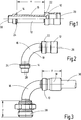
Im Folgenden wird die erfindungsgemäße Lösung anhand von Ausführungsbeispielen eines Verbindungsstückes nach der Zeichnung näher erläutert. Dabei zeigen in prinzipieller und nicht maßstäblicher Darstellung dieIn the following, the solution according to the invention is explained in more detail by means of exemplary embodiments of a connecting piece according to the drawing. This show in principle and not to scale representation of the

1 teilweise im Längsschnitt, teilweise in Ansicht ein geradlinig verlaufendes Rohrstück vorgebbarer Länge mit endseitig angeordneten Anschlussgeometrien; 1 partly in longitudinal section, partly in view of a rectilinear pipe section of predeterminable length with connection geometries arranged at the end;

2 das um 90° gebogene Rohrstück nach der 1; 2 the 90 ° bent piece of pipe after the 1 ;

3 das gebogene Rohrstück nach der 2 mit aufgesetzten Anschlussteilen und einem teilweise dargestellten Schlauchstück; 3 the bent pipe piece after the 2 with attached connection parts and a piece of tubing partially shown;

4 teilweise im Längsschnitt, teilweise in Ansicht die Lösung nach der 3, jedoch ohne eingesetztes Schlauchstück; 4 partly in longitudinal section, partly in view the solution after 3 , but without inserted tube piece;

5 teilweise im Längsschnitt, teilweise in Ansicht das gebogene Rohrstück nach der 2 mit andersgearteten Anschlussteilen wie vorstehend dargestellt; und 5 partly in longitudinal section, partly in view of the bent pipe section after the 2 with different connection parts as shown above; and

6 eine der 5 entsprechende Darstellung mit denselben Anschlussteilen, aber mit verkürztem Rohrstück und mit anderem, geringerem Biegeradius von 45°. 6 one of the 5 corresponding representation with the same connection parts, but with shortened pipe section and with other, lower bending radius of 45 °.

Die 1 zeigt teilweise im Längsschnitt, teilweise in Ansicht ein geradlinig verlaufendes Rohrstück 10 vorgebbarer Länge mit endseitig angeordneten Anschlussgeometrien 12, 14. Das Rohrstück 10 besteht aus einem üblichen Metallwerkstoff und wird bevorzugt im Rahmen einer Drehbearbeitung in spanender Weise aus dem Vollen erhalten, wobei bis auf die Anschlussgeometrie 12 das Rohrstück 10 einen konstanten Innendurchmesser aufweist. Sofern auf eine hochdruckfeste Ausgestaltung verwiesen wird, schließt dies normal druckfeste Anwendungen mit ein. Insbesondere bei den im Folgenden angesprochenen Pneumatikanwendungen belaufen sich die zu beherrschenden Druckwerte auf regelmäßig bis zu 24 bar.The 1 shows partly in longitudinal section, partly in view of a rectilinear pipe section 10 predeterminable length with connection geometries arranged at the end 12 . 14 , The pipe piece 10 consists of a conventional metal material and is preferably obtained in the context of a turning machining in a cutting manner from the solid, with the exception of the connection geometry 12 the pipe section 10 has a constant inner diameter. If reference is made to a high pressure resistant design, this includes normal pressure resistant applications. Particularly in the case of the pneumatic applications mentioned below, the pressure values to be controlled amount to regularly up to 24 bar.

Die 2 zeigt das Rohrstück 10 nach der 1 im gebogenen Zustand, wobei die Biegung hier 90° beträgt. Mithin nehmen die beiden Anschlussgeometrien 12, 14 an den beiden gegenüberliegenden Endbereichen des geradlinig verlaufenden Rohrstückes 10 zwischen sich einen Rohrabschnitt 16 mit konstantem Außendurchmesser auf, der gebogen verläuft und der beim Biegevorgang gemäß der Darstellung nach der 2 mittig mit der größten Krümmung versehen ist. Wie die 1 weiter zeigt, sind die beiden Anschlussgeometrien 12, 14 in spanender Weise voneinander verschieden ausgebildet, um dergestalt voneinander verschiedene Anschlussteile 18, 20 gemäß der Darstellung nach der 3 ff. aufnehmen zu können. Für die Aufnahme dahingehender Anschlussteile 18, 20 ist vorgesehen, dass an den Rohrabschnitt 16 des Rohrstückes 10 mit konstantem Durchmesser sich beidseitig zwei flanschartige Verbreiterungen 22, 24 der Anschlussgeometrien 12 bzw. 14 anschließen, die als breiteste Stellen der Anschlussgeometrien ausgebildet sind, wobei zum freien Ende 26, 28 des Rohrstückes 10 der Durchmesser einer jeden Anschlussgeometrie 12, 14 gegenüber dieser breitesten Stelle 26 bzw. 28 entsprechend reduziert ist.The 2 shows the pipe section 10 after 1 in the bent state, wherein the bend here is 90 °. Consequently, the two connection geometries take 12 . 14 at the two opposite end portions of the rectilinear pipe section 10 between them a pipe section 16 with a constant outer diameter, which is curved and the bending process as shown in the 2 is provided centrally with the largest curvature. As the 1 further shows, the two connection geometries 12 . 14 formed in a manner different from each other, so as to different from each other connecting parts 18 . 20 as shown in the 3 ff. to be able to record. For the recording of these connecting parts 18 . 20 is provided that to the pipe section 16 of the pipe section 10 with constant diameter on both sides two flange extensions 22 . 24 the connection geometries 12 respectively. 14 connect, which are formed as the widest points of the connection geometries, with the free end 26 . 28 of the pipe section 10 the diameter of each connection geometry 12 . 14 opposite to this widest point 26 respectively. 28 is reduced accordingly.

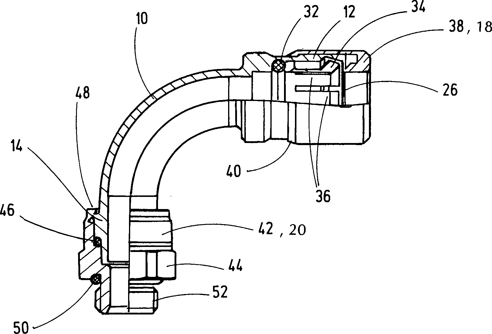
Wie die Darstellung nach der 3 zeigt, wird dann auf die Anschlussgeometrie 12, 14 des Rohrstückes 10 nach den 1 und 2 endseitig das jeweils zuordenbare Anschlussteil 18 bzw. 20 aufgesetzt und mit dem Rohrstück 10 respektive seinen Anschlussgeometrien 12 bzw. 14 verbunden. Die dahingehenden Anschlussteile 18, 20 dienen u. a. der Aufnahme von Schlauchstücken 30, die bevorzugt als Pneumatikschläuche ausgebildet Teil einer nicht näher dargestellten Verrohrung eines Pneumatikverteilnetzes sind. Die dahingehenden Schläuche können flexibel aus Kunststoff ausgebildet sein und sind ebenfalls hochdruckfest wie das Rohrstück 10. Neben einer Pneumatikführung besteht auch die Möglichkeit, andere Medien zu transportieren, wie beispielsweise Druckflüssigkeiten; im Bedarfsfall aber auch pastöse Medien. Insbesondere lassen sich die zuordenbaren Schlauchstücke 30 über die Anschlussteile 18, 20 stationär und druckfest an dem gebogenen Rohrstück 10 nach der 3 in wiederlösbarer Weise festlegen, was im Folgenden anhand von den 4 bis 6 noch näher erläutert werden wird.As the presentation after the 3 shows, then on the connection geometry 12 . 14 of the pipe section 10 after the 1 and 2 at the end the respectively assignable connection part 18 respectively. 20 put on and with the pipe section 10 respectively its connection geometries 12 respectively. 14 connected. The pertinent connecting parts 18 . 20 serve, inter alia, the inclusion of pieces of tubing 30 , which preferably designed as pneumatic hoses part of a non-illustrated piping a pneumatic distribution network. The pertinent hoses can be made of flexible plastic and are also high pressure resistant as the pipe section 10 , In addition to a pneumatic guide, it is also possible to transport other media, such as hydraulic fluids; If necessary, but also pasty media. In particular, the assignable hose pieces can be 30 over the connecting parts 18 . 20 stationary and pressure-resistant on the bent pipe section 10 after 3 determine in a repeatable manner what is described below with reference to the 4 to 6 will be explained in more detail.

Wie sich des Weiteren aus den 1 und 3 ergibt, ist die Rohrlänge X im gebogenen Bereich des Rohrstückes 10, also zwischen den einander benachbarten Seiten der beiden flanschartigen Verbreiterungen 22, 24 gesehen, kleiner gewählt als die Summe der axialen Einbaulängen Y, Z der beiden Anschlussteile 18, 20 auf den zugeordneten Anschlussgeometrien 12, 14, wiederum beginnend mit der Längenermittlung ab der jeweiligen flanschartigen Verbreiterung 22, 24 des Rohrstückes 10. Die dahingehende Einbaulänge X kann auch gleich gewählt werden zu den Summen der genannten axialen Einbaulängen Y und Z. Dergestalt baut der Bogenanschluss sehr kompakt auf, und nach dem Biegen entstehen nahezu keinen geraden zylindrischen Rohrleitungsabschnitte, wie sie ansonsten bei anderen bekannten Bogenwinkeln vorhanden sind, so dass der erfindungsgemäße Bogen ohne Ansatz in die Anschlussstücke oder Anschlussteile 18, 20 übergehen kann, was einer hemmnisfreien Medien- oder Fluidführung zugutekommt, ohne dass sich Medien- oder Fluidpartikel an den Übergangsstellen zu den Anschlussteilen ungewollt absetzen könnten. Auch das Verhältnis von Biegeradius zu Rohrdurchmesser ist in einem Bereich am Ende des technisch Machbaren angesiedelt. Das Verhältnis Biegeradius zu Rohrdurchmesser beträgt dabei 12,7/5 und bei größeren Größen 20,5/7; 21,8/9; 33,9/12,5; und 44,3/30.As further from the 1 and 3 results, the tube length X is in the bent portion of the pipe section 10 , ie between the adjacent sides of the two flange-like widenings 22 . 24 seen, chosen smaller than the sum of the axial installation lengths Y, Z of the two connecting parts 18 . 20 on the assigned connection geometries 12 . 14 , again starting with the length determination from the respective flange-like broadening 22 . 24 of the pipe section 10 , The pertinent installation length X can also be chosen equal to the sums of said axial installation lengths Y and Z. In this way, the arc connection builds very compact, and after bending arise almost no straight cylindrical pipe sections, as they are otherwise available at other known arc angles, so that the arc of the invention without approach in the fittings or connecting parts 18 . 20 can pass, which benefits an interference-free media or fluid management, without media or fluid particles could settle unintentionally at the transition points to the connecting parts. Also, the ratio of bending radius to pipe diameter is located in a range at the end of the technically feasible. The ratio of bending radius to pipe diameter is 12.7 / 5 and for larger sizes 20.5 / 7; 21.8 / 9; 33.9 / 12.5; and 44.3 / 30.

Je nach Ausgestaltung von einzelnen Anschlussteilen, die auch zu den Anschlussteilen 18, 20 verschieden sein können, lassen sich diese neben Bördeln auch in anderer Weise mit den entsprechenden Anschlussgeometrien des Rohrstückes 10 verbinden, beispielsweise mittels Aufpressen, Aufschweißen oder über das Herstellen einer Klippverbindung. Ferner besteht die Möglichkeit des Aufschraubens, was bei der Ausführung nach den 5 und 6 noch näher erläutert werden wird.Depending on the design of individual connection parts, which are also the connection parts 18 . 20 can be different, these can be in addition to flanging in other ways with the corresponding connection geometries of the pipe section 10 connect, for example by means of pressing, welding or making a clip connection. Furthermore, there is the possibility of unscrewing, which in the execution of the 5 and 6 will be explained in more detail.

Das in der 4 dargestellte Anschlussteil 18 weist innenumfangsseitig eine Stufe auf, in die ein O-Dichtring 32 als Dichtmittel klemmend festgelegt ist. Zum Klemmen des O-Dichtringes 32 ist dabei weiter ein Spanneinsatz 34 in Form einer Spannzange vorgesehen, deren einzelne Spannbacken 36 in üblicher und daher nicht mehr näher beschriebener Art und Weise dem Festlegen des freien Endes eines zuordenbaren, eingeführten Schlauchstückes 30 dienen. Beim Einführen des Schlauchstückes 30 in den Spanneinsatz 34 spreizen sich die Spannbacken 36 an ihrem dem freien Ende 26 des Rohrstückes 10 zugewandten Ende auf, und mit Einschieben des Schlauchstückes 30 federn diese in ihre das Schlauchstück 30 klemmende, in der 4 gezeigte Ausgangslage zurück. Damit der Spanneinsatz 34 im Inneren der Anschlussgeometrie 12 verbleibt, ist ein Überwurfteil 38 vorgesehen, das mit seinem inneren Ende in Anlage mit der freien Stirnseite des Spanneinsatzes 34 ist und mit seinem anderen freien Ende 40 umgebördelt einen nach innen vorspringenden Bördelrand 40 ausbildet, mit dem das Überwurfteil 38 in Position auf der Außenumfangsseite der Anschlussgeometrie 12 gehalten ist. Sollte der Bördelrand 40 nicht allzu fest auf der Anschlussgeometrie 12 festgelegt sein, besteht auch die Möglichkeit, dass das Überwurfteil 38 drehbar auf der Anschlussgeometrie 12 in Form eines Anschlussstutzens gehalten ist.That in the 4 illustrated connection part 18 has a level on the inner circumference, into which an O-ring 32 as a sealing means is determined by clamping. For clamping the O-ring 32 is still a clamping insert 34 provided in the form of a collet, whose individual jaws 36 in the usual and therefore not described in more detail way the setting of the free end of a assignable, imported piece of tubing 30 serve. When inserting the hose piece 30 in the clamping insert 34 spread the jaws 36 at her free end 26 of the pipe section 10 facing the end, and with insertion of the hose piece 30 These spring into their the hose piece 30 stuck in the 4 shown starting position back. Thus the clamping insert 34 inside the connection geometry 12 remains, is a cap part 38 provided, with its inner end in contact with the free end face of the clamping insert 34 is and with its other free end 40 flanged an inwardly projecting flange 40 forms, with the cap part 38 in position on the outer peripheral side of the connection geometry 12 is held. Should the Bördelrand 40 not too tight on the connection geometry 12 be fixed, there is also the possibility that the cap part 38 rotatable on the connection geometry 12 is held in the form of a connecting piece.

Am anderen Ende des Rohrstückes 10 ist auf der Anschlussgeometrie 14 ein Einschraubteil 42 festgelegt mit einer Sechskantanfasung 44. Auch hier ist wiederum ein Dichtmittel in Form eines weiteren O-Dichtringes 46, diesmal in einer stufenförmigen Verbreiterung der Anschlussgeometrie 14 angeordnet und mittels des Einschraubteils 42 klemmend in dichtender Position gehalten, wobei wiederum über einen Bördelrand 48, der die Verbreiterung 24 der Anschlussgeometrie 14 übergreift, das Einschraubteil in Position auf dem Rohrstück 10 gehalten ist. Zur Schonung des weiteren O-Dichtringes 46 ist die dahingehende Bördelverbindung feststehend ausgebildet. Auf seiner freien Stirnseite schließt sich der Sechskantanfasung 44 ein weiterer, dritter O-Dichtring 50 an, und ein nicht näher dargestelltes Schlauchstück eines Pneumatikschlauches lässt sich dergestalt in dichtender Weise auf ein unteres Außengewinde 52 des Einschraubteils 42 anschließen. Dergestalt ist eine medienführende Verbindung zwischen den beiden Anschlussteilen 18, 20 und dem dazwischenliegenden Rohrstück 10 hergestellt.At the other end of the pipe section 10 is on the connection geometry 14 a screw-in 42 set with a hexagonal chamfer 44 , Again, in turn, a sealant in the form of another O-ring seal 46 , this time in a stepped broadening of the connection geometry 14 arranged and by means of the screw 42 clamped in a sealing position, again with a crimping edge 48 that's the broadening 24 the connection geometry 14 engages, the screw in position on the pipe section 10 is held. To protect the other O-ring 46 is the pertinent flare fixed. On its free front side, the hexagonal chamfering closes 44 another, third O-ring 50 on, and a piece of hose of a pneumatic hose not shown in detail can be in a sealing manner to a lower external thread 52 of the screw-in part 42 connect. Such is a media-leading connection between the two connecting parts 18 . 20 and the intermediate pipe section 10 produced.

Das gebogene rohrförmige Verbindungselement nach den 5 und 6 wird nur noch insofern beschrieben, als es sich wesentlich von der vorangehenden Ausführungsform unterscheidet. Bei der Ausführungsform nach der 5 ist das Überwurfteil 38 als Aufschraubteil ausgebildet, das sich mit seinem Innengewinde auf ein Außengewinde 54 der Anschlussgeometrie 12 aufschrauben lässt. Bei dem dahingehenden Aufschraubvorgang wird über einen ringförmigen Mitnahmesteg 56 das Spannelement für ein Schlauchstück 30 in Form der Spannzange 34 mitgenommen und die einzelnen Spannbacken 36 werden für einen Öffnungs- und Schließungsvorgang zum Festlegen des in 5 nicht näher dargestellten Schlauchstückes 30 über Steuer- und Führungsschrägen am freien Ende 26 der ersten Anschlussgeometrie 12 sinnfällig angesteuert. Ferner verfügt das Überwurfteil 38 nach der 5 an seinem freien äußeren Ende über eine Sechskantanfasung 58 zwecks schraubender oder drehender Bewegung des Überwurfteils 38 mittels eines geeigneten, nicht näher dargestellten Betätigungswerkzeuges (Gabelschlüssel).The bent tubular connecting element according to 5 and 6 is described only insofar as it differs significantly from the preceding embodiment. In the embodiment of the 5 is the cap part 38 designed as a screw-on, which with its internal thread on an external thread 54 the connection geometry 12 screw it on. In the pertinent Aufschraubvorgang is an annular carrier web 56 the tensioning element for a hose piece 30 in the form of the collet 34 taken along and the individual jaws 36 be for an opening and Closing process to set the in 5 not shown hose piece 30 over control and guide bevels at the free end 26 the first connection geometry 12 clearly driven. Furthermore, has the cap part 38 after 5 at its free outer end via a hexagonal chamfer 58 for the purpose of screwing or rotating movement of the cap part 38 by means of a suitable, not shown actuating tool (open-end wrench).

Das Einschraubteil 42, das wiederum am unteren Ende des Rohrstückes 10 angebracht ist, weist diesmal neben der Sechskantanfasung 44 als Gegenstück noch eine Kontermutter 60 auf, die über zuordenbare Innen- und Außengewindestrecken am freien oberen Ende des Einschraubteils 42 mit diesem verbindbar ist und dabei über einen innerhalb der Kontermutter 60 und in einer Außenausnehmung des Rohrstückes 10 angeordneten Sprengring 62 drehbar auf dem Rohrstück 10 gehalten ist, um dergestalt hemmnisfrei den Aufschraubvorgang auf das Außengewinde des Einschraubteils 42 vornehmen zu können. Dergestalt lässt sich das Einschraubteil 42, das an seinem unteren freien Ende gleichfalls über ein Außengewinde 52 verfügt zwecks Festlegen eines nicht näher dargestellten aufschraubbaren Schlauchstückes 30, an die Anschlussgeometrie 14 des Rohrstückes 10 festlegen. Dabei kommt in Blickrichtung auf die 5 gesehen das freie untere Ende 28 des Rohrstückes 10 in Anlage mit einer Innenstufung 64 des Einschraubteils 42. Die Ausführungsform nach der 6 entspricht der Ausführungsform nach der 5 mit der Maßgabe, dass anstelle eines Biegewinkels für das Rohrstück 10 von 90° ein solcher von 45° gewählt ist.The screw-in part 42 , in turn, at the lower end of the pipe section 10 attached, points this time next to the hexagonal chamfering 44 as counterpart still a lock nut 60 on, the assignable inside and Außengewindestrecken at the free upper end of the screw 42 with this is connectable and thereby one inside the lock nut 60 and in an outer recess of the pipe section 10 arranged snap ring 62 rotatable on the pipe section 10 is held in such a way without inhibiting the screwing on the external thread of the screw 42 to be able to make. In this way, the screw-in can be 42 , which also has an external thread at its lower free end 52 has for the purpose of setting a screw-on piece of tubing, not shown 30 , to the connection geometry 14 of the pipe section 10 establish. It comes in the direction of the 5 seen the free bottom end 28 of the pipe section 10 in plant with an interior grading 64 of the screw-in part 42 , The embodiment of the 6 corresponds to the embodiment of the 5 with the proviso that instead of a bending angle for the pipe section 10 from 90 ° one of 45 ° is chosen.

Als standardisiertes Normteil lässt sich das erfindungsgemäße Verbindungselement in einer Vielzahl von verschiedensten Verrohrungen zum Medientransport einsetzen, und die jeweilige Außengestaltung des Verbindungselementes gemäß den Darstellungen nach den 3 bis 6 macht deutlich, dass eine im Wesentlichen geschlossene Außenkontur erreicht ist unter Einbezug der jeweiligen Anschlussteile 18, 20, so dass sich evtl. im Betrieb auftretende Verschmutzungen auf dem Verbindungselement nicht ungewollt absetzen können, und sofern solche Verschmutzungspartikel doch auftreten sollten, lassen diese sich leicht von der Oberfläche des Verbindungselementes abreinigen. Insoweit wird das erfindungsgemäße Verbindungselement bevorzugt in der Lebensmittelindustrie und in der pharmazeutischen Industrie Anwendung finden können.As a standardized standard part, the connecting element according to the invention in a variety of different casings for media transport can be used, and the respective outer design of the connecting element according to the representations of the 3 to 6 makes it clear that a substantially closed outer contour is achieved by including the respective connecting parts 18 . 20 so that any soiling occurring during operation on the connecting element can not unintentionally settle, and if such dirt particles should occur, they can be easily cleaned from the surface of the connecting element. In that regard, the connecting element according to the invention may preferably be used in the food industry and in the pharmaceutical industry.

ZITATE ENTHALTEN IN DER BESCHREIBUNG QUOTES INCLUDE IN THE DESCRIPTION

Diese Liste der vom Anmelder aufgeführten Dokumente wurde automatisiert erzeugt und ist ausschließlich zur besseren Information des Lesers aufgenommen. Die Liste ist nicht Bestandteil der deutschen Patent- bzw. Gebrauchsmusteranmeldung. Das DPMA übernimmt keinerlei Haftung für etwaige Fehler oder Auslassungen.This list of the documents listed by the applicant has been generated automatically and is included solely for the better information of the reader. The list is not part of the German patent or utility model application. The DPMA assumes no liability for any errors or omissions.

Zitierte PatentliteraturCited patent literature

  • DE 102007016766 A1 [0002] DE 102007016766 A1 [0002]
  • DE 2714782 A1 [0004, 0010] DE 2714782 A1 [0004, 0010]

Claims (10)

Verfahren zum Herstellen eines gebogenen rohrförmigen Verbindungselementes mit zumindest den folgenden Herstellschritten: – Durchführen einer spanenden Bearbeitung für ein metallisches, geradlinig verlaufendes Rohrstück (10) vorgebbarer Länge unter Einbezug von Anschlussgeometrien (12, 14) für die Aufnahme von separaten Anschlussteilen (18, 20), die dem Anschließen einer medienführenden Verrohrung dienen, – Durchführen eines Biegevorganges für das derart spanend erstellte Rohrstück (10) mit einem vorgebbaren Biegeradius, vorzugsweise von bis zu 90 Grad, und – Anbringen des jeweiligen Anschlussteils (18, 20) an der zuordenbaren endseitigen Anschlussgeometrie (12, 14) des Rohrstückes (10).Method for producing a curved tubular connecting element with at least the following manufacturing steps: - performing a machining operation for a metallic, rectilinear pipe section ( 10 ) of predeterminable length including connection geometries ( 12 . 14 ) for receiving separate connection parts ( 18 . 20 ), which serve to connect a media-carrying piping, - performing a bending operation for the thus produced machined pipe section ( 10 ) with a predefinable bending radius, preferably of up to 90 degrees, and - attaching the respective connection part ( 18 . 20 ) at the assignable terminal connection geometry ( 12 . 14 ) of the pipe section ( 10 ). Verfahren nach Anspruch 1, dadurch gekennzeichnet, dass das geradlinig verlaufende Rohrstück (10) als spanende Bearbeitung eine Drehbearbeitung erfährt und dass der Biegevorgang ein Kaltumformvorgang ist.A method according to claim 1, characterized in that the rectilinear pipe section ( 10 ) undergoes a turning machining as machining and that the bending process is a cold forming process. Verfahren nach Anspruch 1 oder 2, dadurch gekennzeichnet, dass die Anschlussgeometrien in den beiden gegenüberliegenden Endbereichen (26, 28) des geradlinig verlaufenden Rohrstückes (10) zwischen sich einen Rohrabschnitt (16) mit konstantem Durchmesser aufnehmen, der gebogen wird und der beim Biegevorgang mittig mit der größten Krümmung versehen wird.Method according to claim 1 or 2, characterized in that the connection geometries in the two opposite end regions ( 26 . 28 ) of the rectilinear pipe section ( 10 ) between a pipe section ( 16 ) with a constant diameter, which is bent and which is provided in the middle of the bending process with the largest curvature. Verfahren nach einem der vorstehenden Ansprüche, dadurch gekennzeichnet, dass die am Rohrstück (10) gegenüberliegenden drehend hergestellten Anschlussgeometrien (12, 14) voneinander verschieden ausgestaltet werden.Method according to one of the preceding claims, characterized in that the (at the piece of pipe 10 ) opposite rotationally produced connecting geometries ( 12 . 14 ) are configured differently from each other. Verfahren nach einem der vorstehenden Ansprüche, dadurch gekennzeichnet, dass an den Rohrabschnitt (16) des Rohrstückes (10) mit konstantem Durchmesser beidseitig zwei flanschartige Verbreiterungen (22, 24) der Anschlussgeometrien (12, 14) angeordnet werden, die als breiteste Stellen der Anschlussgeometrien (12, 14) vorgesehen werden, und dass zum freien Ende des Rohrstückes (10) der Durchmesser einer jeden Anschlussgeometrie (12, 14) gegenüber dieser breitesten Stelle (22, 24) reduziert wird.Method according to one of the preceding claims, characterized in that to the pipe section ( 16 ) of the pipe section ( 10 ) with constant diameter on both sides two flange-like spacers ( 22 . 24 ) of the connection geometries ( 12 . 14 ), which are the widest points of the connection geometries ( 12 . 14 ) are provided, and that to the free end of the pipe section ( 10 ) the diameter of each connection geometry ( 12 . 14 ) to this widest point ( 22 . 24 ) is reduced. Verfahren nach einem der vorstehenden Ansprüche, dadurch gekennzeichnet, dass die Anschlussteile (18, 20) nach deren Festlegen auf den jeweils zuordenbaren Anschlussgeometrien (12, 14) des Rohrstückes (10) zumindest teilweise außen- und/oder innenumfangsseitig mit dem Rohrstück (10) ein Dichtmittel begrenzen, vorzugsweise in Form eines O-Dichtringes (32, 46), das klemmend festgelegt wird.Method according to one of the preceding claims, characterized in that the connecting parts ( 18 . 20 ) after having defined them on the respectively assignable connection geometries ( 12 . 14 ) of the pipe section ( 10 ) at least partially outside and / or inside peripheral side with the pipe section ( 10 ) define a sealant, preferably in the form of an O-ring ( 32 . 46 ), which is determined by clamping. Verfahren nach einem der vorstehenden Ansprüche, dadurch gekennzeichnet, dass zumindest ein Teil der Anschlussteile (18, 20) fest oder drehbar auf den Anschlussgeometrien (12, 14) des Rohrstückes (10) montiert werden.Method according to one of the preceding claims, characterized in that at least a part of the connecting parts ( 18 . 20 ) fixed or rotatable on the connection geometries ( 12 . 14 ) of the pipe section ( 10 ) to be assembled. Verfahren nach einem der vorstehenden Ansprüche, dadurch gekennzeichnet, dass die Rohrlänge (X) im gebogenen Bereich des Rohrstückes (10) gleich oder kleiner gewählt wird als die Summe der axialen Einbaulängen (Y, Z) der beiden Anschlussteile (18, 20) auf den zugeordneten Anschlussgeometrien (12, 14) beginnend mit der Längenermittlung ab der jeweiligen flanschartigen Verbreiterung (22, 24) des Rohrstückes (10).Method according to one of the preceding claims, characterized in that the tube length (X) in the bent portion of the pipe section ( 10 ) is chosen equal to or smaller than the sum of the axial installation lengths (Y, Z) of the two connecting parts ( 18 . 20 ) on the assigned connection geometries ( 12 . 14 ) starting with the length determination from the respective flange-like widening ( 22 . 24 ) of the pipe section ( 10 ). Verfahren nach einem der vorstehenden Ansprüche, dadurch gekennzeichnet, dass zumindest eine Anschlussgeometrie (12) des Rohrstückes (10) innenumfangsseitig mit einer Ausnehmung derart versehen wird, dass eine Spannzange (34) des Anschlussteiles (18) aufgenommen wird, die an einem endseitigen Teil der anzuschließenden Verrohrung angreifend ausgestaltet ist.Method according to one of the preceding claims, characterized in that at least one connection geometry ( 12 ) of the pipe section ( 10 ) is provided on the inner peripheral side with a recess such that a collet chuck ( 34 ) of the connection part ( 18 ) is taken, which is designed to be attacking on an end-side part of the pipe to be connected. Verbindungselement, hergestellt nach einem der vorstehenden Ansprüche mit einem gebogenen, spanend bearbeiteten Rohrstück (10), das endseitig Anschlussgeometrien (12, 14) für Anschlussteile (18, 20) aufweist, mittels der das Verbindungselement mit Teilen (30) einer medienführenden Verrohrung verbindbar ist.Connecting element, produced according to one of the preceding claims with a bent, machined piece of pipe ( 10 ), the terminal connection geometries ( 12 . 14 ) for connecting parts ( 18 . 20 ), by means of which the connecting element with parts ( 30 ) is connectable to a media-carrying piping.
DE102016005299.6A 2016-05-02 2016-05-02 Method for producing a curved tubular connecting element Pending DE102016005299A1 (en)

Priority Applications (8)

Application Number Priority Date Filing Date Title
DE102016005299.6A DE102016005299A1 (en) 2016-05-02 2016-05-02 Method for producing a curved tubular connecting element
MX2018013350A MX2018013350A (en) 2016-05-02 2017-03-29 Method for producing a curved tubular connection element.
US16/097,651 US11103965B2 (en) 2016-05-02 2017-03-29 Method for producing a curved tubular connection element
PCT/EP2017/000383 WO2017190823A1 (en) 2016-05-02 2017-03-29 Method for producing a curved tubular connection element
EP17714640.4A EP3452236A1 (en) 2016-05-02 2017-03-29 Method for producing a curved tubular connection element
CA3022649A CA3022649A1 (en) 2016-05-02 2017-03-29 Method for producing a bent tubular connection element
CN201780033154.2A CN109414743A (en) 2016-05-02 2017-03-29 Method for manufacturing curved tubular connecting element
JP2018558350A JP2019514696A (en) 2016-05-02 2017-03-29 Method of manufacturing a curved tubular coupling element

Applications Claiming Priority (1)

Application Number Priority Date Filing Date Title
DE102016005299.6A DE102016005299A1 (en) 2016-05-02 2016-05-02 Method for producing a curved tubular connecting element

Publications (1)

Publication Number Publication Date
DE102016005299A1 true DE102016005299A1 (en) 2017-11-02

Family

ID=58461258

Family Applications (1)

Application Number Title Priority Date Filing Date
DE102016005299.6A Pending DE102016005299A1 (en) 2016-05-02 2016-05-02 Method for producing a curved tubular connecting element

Country Status (8)

Country Link
US (1) US11103965B2 (en)
EP (1) EP3452236A1 (en)
JP (1) JP2019514696A (en)
CN (1) CN109414743A (en)
CA (1) CA3022649A1 (en)
DE (1) DE102016005299A1 (en)
MX (1) MX2018013350A (en)
WO (1) WO2017190823A1 (en)

Families Citing this family (8)

* Cited by examiner, † Cited by third party
Publication number Priority date Publication date Assignee Title
CN109630793B (en) * 2019-02-13 2023-11-28 宁波固远管件有限公司 Hydraulic bending lining core integrated piece and processing method thereof
US11585687B2 (en) 2019-04-02 2023-02-21 Malema Engineering Corporation Polymer-based Coriolis mass flow sensor fabricated through casting
US11300435B2 (en) 2020-04-10 2022-04-12 Malema Engineering Corporation Coriolis mass flow sensors having different resonant frequencies
US11619532B2 (en) 2020-04-10 2023-04-04 Malema Engineering Corporation Replaceable, gamma sterilizable Coriolis flow sensors
CN111810749B (en) * 2020-09-15 2020-11-24 山东龙口油管有限公司 Automobile oil pipe connecting device
US12296210B2 (en) * 2021-03-19 2025-05-13 American Fire Equipment, Inc. Extension assembly for a fire suppression spray nozzle
CN116197282A (en) * 2023-05-04 2023-06-02 佛山市腾华自动化机械有限公司 Bending machine
US12372390B2 (en) 2023-05-08 2025-07-29 Malema Engineering Corporation Coriolis mass flow rate sensor

Citations (5)

* Cited by examiner, † Cited by third party
Publication number Priority date Publication date Assignee Title
DE630724C (en) *
AT179463B (en) * 1952-03-14 1954-09-10 Eduard Starlinger Method and device for the production of seamless, thick-walled pipe bends
DE2714782A1 (en) 1977-04-02 1978-10-05 Bertrams Ag Bender for thin-wall pipes - has mandrel built up from discs to fit in bend during external working by rollers
DE102007016766A1 (en) 2006-09-08 2008-03-27 Horst Severyns Injection moulding unit, comprises a multi-sectional mould composed of outer sections and core sections, and a swivel unit
DE102012111803A1 (en) * 2012-12-05 2014-06-05 Presswerk Struthütten GmbH Pressure cell component and method for its production

Family Cites Families (30)

* Cited by examiner, † Cited by third party
Publication number Priority date Publication date Assignee Title
US1826077A (en) * 1929-07-29 1931-10-06 York Band Instr Company Method and apparatus for treating drawn tubes
US1913490A (en) * 1930-10-10 1933-06-13 Francis M Kepler Method of making angular tubing bends
US2002282A (en) * 1933-05-04 1935-05-21 Tessky Karl Workpiece guide for machine tools
US2983995A (en) * 1955-04-19 1961-05-16 Gresse Andre Bending process
US2988385A (en) * 1958-05-13 1961-06-13 Foelester Richard Combination pipe union elbow
US3055396A (en) * 1961-05-18 1962-09-25 Fed Pacific Electric Co Hydropneumatic accumulator
US3243873A (en) * 1965-04-26 1966-04-05 Homer J Steel Tube bending
US3752506A (en) * 1972-09-18 1973-08-14 R Fouts Sealed fitting for reinforced hose
JPH0417923A (en) * 1990-05-09 1992-01-22 Matsumura Kikai Seisakusho:Kk Manufacture of elbow fitting for piping
DE9007807U1 (en) 1990-05-11 1996-11-28 Ortwein, Ernst-Georg, 73061 Ebersbach Siphon bracket for plumbing
DE4015151A1 (en) * 1990-05-11 1991-11-14 Ortwein Ernst Georg Syphon angle for sanitary installation - has overlength adjustable on final assembly and sealing nipple with support lip locating on wall front edge
DE19500953C1 (en) * 1995-01-14 1996-07-25 Esser Werke Gmbh & Co Kg Arcuate section of tube for fitting in piping for hydraulic or pneumatic conveying of solid materials
AT406453B (en) 1996-02-19 2000-05-25 Vaillant Gmbh METHOD FOR PRODUCING A TUBE WITH A BAND
WO1999058814A1 (en) * 1998-05-14 1999-11-18 Fike Corporation Downhole dump valve
CA2386574A1 (en) * 1999-09-09 2001-03-15 R. Conrader Company Tube fitting
US6473981B2 (en) * 2001-02-13 2002-11-05 Victaulic Company Of America Diameter indicator for use with groove forming tools
US7300074B1 (en) * 2003-12-22 2007-11-27 Pelletron Corporation Elbow fitting with step feature for pneumatic transport system
US6951354B1 (en) * 2003-12-22 2005-10-04 Pelletron Corporation Elbow fitting for pneumatic transport system
US7524466B2 (en) * 2004-01-07 2009-04-28 Longmark Industries, L.L.C. Environmental sanitizer and odor remover for purification of foods, surfaces, air and water with disposable ozone generation electrode, pressure/flow adaptable venturi injector and aqueous phase filter device
DE102005051766B4 (en) * 2005-10-27 2009-02-26 Esser-Werke Gmbh & Co. Kg Pipe bend and method for producing a pipe bend
JP2007331021A (en) 2006-06-19 2007-12-27 Asoh Kk Method of bending mouth portion of valve and its apparatus
CN102330723A (en) * 2010-07-13 2012-01-25 新秩序投资119股份有限公司 Pipe fitting
RU2636147C1 (en) * 2011-08-27 2017-11-21 Вокхардт Лимитед 1,6-diazabicyclo[3,2,1]octan-7-one derivatives and their application for bacterial infections treatment
US20130174935A1 (en) * 2012-01-10 2013-07-11 II Curtis R. Patterson Variable thin walled duct with bend
JP5874828B2 (en) * 2012-07-03 2016-03-02 富士通株式会社 Control target flow specifying program, control target flow specifying method, and control target flow specifying apparatus
US10047884B2 (en) * 2013-12-04 2018-08-14 Flash Line Technologies, Inc. Pipe connectors and systems
SE537529C2 (en) * 2014-02-17 2015-06-02 Janos Keller Device for a pipe bending tool
US9829124B2 (en) * 2014-06-18 2017-11-28 United Technologies Corporation Double wall tube assemblies
CN204677966U (en) * 2015-05-21 2015-09-30 浙江三叶机械有限公司 One can fix isometrical angle coupling
CN205136913U (en) * 2015-11-04 2016-04-06 河北亚大汽车塑料制品有限公司 Novel formula quick connector cut straightly

Patent Citations (5)

* Cited by examiner, † Cited by third party
Publication number Priority date Publication date Assignee Title
DE630724C (en) *
AT179463B (en) * 1952-03-14 1954-09-10 Eduard Starlinger Method and device for the production of seamless, thick-walled pipe bends
DE2714782A1 (en) 1977-04-02 1978-10-05 Bertrams Ag Bender for thin-wall pipes - has mandrel built up from discs to fit in bend during external working by rollers
DE102007016766A1 (en) 2006-09-08 2008-03-27 Horst Severyns Injection moulding unit, comprises a multi-sectional mould composed of outer sections and core sections, and a swivel unit
DE102012111803A1 (en) * 2012-12-05 2014-06-05 Presswerk Struthütten GmbH Pressure cell component and method for its production

Also Published As

Publication number Publication date
MX2018013350A (en) 2019-08-05
JP2019514696A (en) 2019-06-06
US11103965B2 (en) 2021-08-31
WO2017190823A1 (en) 2017-11-09
CA3022649A1 (en) 2017-11-09
CN109414743A (en) 2019-03-01
US20190134763A1 (en) 2019-05-09
EP3452236A1 (en) 2019-03-13

Similar Documents

Publication Publication Date Title
DE102016005299A1 (en) Method for producing a curved tubular connecting element
EP3596377B1 (en) Fitting for connecting to at least one pipe and method for producing a connection
AT401417B (en) SLIDING SLEEVE CONNECTION FOR PLASTIC PIPES
DE3879674T2 (en) QUICK COUPLING FOR PIPES OR HOSES WITH A TAPERED RING.
DE19631574C1 (en) Pressed union between pipes
EP0361630A1 (en) Method and device and press-fitting for manufacturing a perfect, leak-proof junction of pipes
EP0343395A2 (en) Pressfitting, tap and method of manufacture
WO2011029687A1 (en) Screwed pipe joint and method for the production thereof
DE102010055531A1 (en) Press fitting and its use
DE3838935A1 (en) CLUTCH PIECE
DE19520099C3 (en) Pipe connection and process for its manufacture
DE102009017571A1 (en) Pipe bends producing method, involves forming molding surface of one press tool part by end portions of sheet material during locking of press tool parts until final shape of pipe bend results
EP2226545B1 (en) Pipe element and use of same
DE19941577C2 (en) Pipe connection and process for its manufacture
EP0306770B1 (en) Sticking joint for compressed air lines out of plastic
DE102013015895A1 (en) Press fitting and connection arrangement with such a press fitting
EP3364091A1 (en) Fitting
DE7505624U (en) PIPE WITH PIPE CONNECTING DEVICE
DE202004007321U1 (en) Connection between the end of a corrugated pipe and a connector
DE29721224U1 (en) Line connection
WO2014131380A1 (en) Pipe manifold
DE102005033482A1 (en) connecting device
DE3029621A1 (en) FORM AND GROOVE DEVICE FOR PIPE END
DE29818534U1 (en) Connection for pipe and / or hose lines
DE19844878A1 (en) Method and appliance for producing a pressure join comprise tool, with drive mechanism and pressure jaws with pressure profile

Legal Events

Date Code Title Description
R012 Request for examination validly filed
R081 Change of applicant/patentee

Owner name: EISELE GMBH, DE

Free format text: FORMER OWNER: EISELE PNEUMATICS GMBH & CO. KG, 71332 WAIBLINGEN, DE

R082 Change of representative

Representative=s name: ABP BURGER RECHTSANWALTSGESELLSCHAFT MBH, DE

R016 Response to examination communication