DE102015114697A1 - Holding frame for connector modules - Google Patents
Holding frame for connector modules Download PDFInfo
- Publication number
- DE102015114697A1 DE102015114697A1 DE102015114697.5A DE102015114697A DE102015114697A1 DE 102015114697 A1 DE102015114697 A1 DE 102015114697A1 DE 102015114697 A DE102015114697 A DE 102015114697A DE 102015114697 A1 DE102015114697 A1 DE 102015114697A1
- Authority
- DE
- Germany
- Prior art keywords
- holding frame
- blocking element
- halves
- frame according
- mandrel
- Prior art date
- Legal status (The legal status is an assumption and is not a legal conclusion. Google has not performed a legal analysis and makes no representation as to the accuracy of the status listed.)
- Granted
Links
Images


Classifications
-
- H—ELECTRICITY
- H01—ELECTRIC ELEMENTS
- H01R—ELECTRICALLY-CONDUCTIVE CONNECTIONS; STRUCTURAL ASSOCIATIONS OF A PLURALITY OF MUTUALLY-INSULATED ELECTRICAL CONNECTING ELEMENTS; COUPLING DEVICES; CURRENT COLLECTORS
- H01R13/00—Details of coupling devices of the kinds covered by groups H01R12/70 or H01R24/00 - H01R33/00
- H01R13/46—Bases; Cases
- H01R13/516—Means for holding or embracing insulating body, e.g. casing, hoods
- H01R13/518—Means for holding or embracing insulating body, e.g. casing, hoods for holding or embracing several coupling parts, e.g. frames
-
- H—ELECTRICITY
- H01—ELECTRIC ELEMENTS
- H01R—ELECTRICALLY-CONDUCTIVE CONNECTIONS; STRUCTURAL ASSOCIATIONS OF A PLURALITY OF MUTUALLY-INSULATED ELECTRICAL CONNECTING ELEMENTS; COUPLING DEVICES; CURRENT COLLECTORS
- H01R13/00—Details of coupling devices of the kinds covered by groups H01R12/70 or H01R24/00 - H01R33/00
- H01R13/46—Bases; Cases
- H01R13/502—Bases; Cases composed of different pieces
- H01R13/512—Bases; Cases composed of different pieces assembled by screw or screws
-
- H—ELECTRICITY
- H01—ELECTRIC ELEMENTS
- H01R—ELECTRICALLY-CONDUCTIVE CONNECTIONS; STRUCTURAL ASSOCIATIONS OF A PLURALITY OF MUTUALLY-INSULATED ELECTRICAL CONNECTING ELEMENTS; COUPLING DEVICES; CURRENT COLLECTORS
- H01R13/00—Details of coupling devices of the kinds covered by groups H01R12/70 or H01R24/00 - H01R33/00
- H01R13/46—Bases; Cases
- H01R13/514—Bases; Cases composed as a modular blocks or assembly, i.e. composed of co-operating parts provided with contact members or holding contact members between them
Abstract
Die Erfindung betrifft einen Halterahmen (1), in welchen Steckverbindermodule (19) einsetzbar sind, wobei der Halterahmen (1) aus zwei miteinander verbindbaren Hälften (4, 5) besteht, wobei der Halterahmen (1) zumindest ein erstes Sperrelement (7) aufweist und wobei die Hälften (4, 5) über das erste Sperrelement (7) in zumindest zwei Positionen zueinander ausrichtbar sind. Das erste Sperrelement (7) ist einseitig an einer Hälfte (4) des Halterahmens (1) fixiert und anderseitig kraftschlüssig mit der anderen Hälfe (5) des Halterahmens (1) verbunden. Der Halterahmen (1) weist ein zweites Sperrelement (15) auf, wobei das zweite Sperrelement (15) einseitig an der ersten Hälfte (4) des Halterahmens (1) fixiert ist und anderseitig mit der zweiten Hälfte (5) des Halterahmens (1) formschlüssig verbunden ist und wobei die formschlüssige Verbindung durch eine Bewegung des zweiten Fixierblechs (15), die von einer Stirnfläche der zweiten Hälfte (5) axial weggerichtet ist, lösbar ist. The invention relates to a holding frame (1) in which connector modules (19) can be inserted, wherein the holding frame (1) consists of two interconnectable halves (4, 5), wherein the holding frame (1) has at least one first blocking element (7) and wherein the halves (4, 5) via the first blocking element (7) in at least two positions are aligned with each other. The first blocking element (7) is fixed on one side to one half (4) of the holding frame (1) and on the other side frictionally connected to the other half (5) of the holding frame (1). The holding frame (1) has a second blocking element (15), wherein the second blocking element (15) is fixed on one side to the first half (4) of the holding frame (1) and on the other side to the second half (5) of the holding frame (1). is positively connected and wherein the positive connection by a movement of the second fixing plate (15) which is axially directed away from an end face of the second half (5), is releasable.

Description
Die Erfindung geht aus von einem Halterahmen für Steckverbindermodule nach dem Oberbegriff des unabhängigen Anspruchs 1.The invention relates to a holding frame for connector modules according to the preamble of
Derartige Halterahmen dienen zur Halterung von Steckverbindermodulen, wobei der Halterahmen mit verschiedenen Steckverbindermodulen bestückt und anschließend in ein Steckverbindergehäuse eingesetzt und mit diesem verschraubt wird. Dabei muss der Halterahmen mechanisch stabil sein, um den auftretenden Steck- und Ziehkräften beim Zusammenfügen bzw. Trennen der Steckverbindung standhalten zu können. Such support frames are used to hold connector modules, the support frame equipped with various connector modules and then inserted into a connector housing and bolted to it. In this case, the support frame must be mechanically stable in order to withstand the insertion and pulling forces occurring when assembling or disconnecting the connector can.
Stand der TechnikState of the art
Aus der
Der Halterahmen der
Bei erfolgreicher Bestückung des Halterahmens mit Steckverbindermodulen muss dieser in einen geschlossen Zustand beziehungsweise in eine geschlossene Position gebracht werden, damit die Steckverbindermodule fixiert sind. Für den geschlossenen Zustand des Halterahmens des Standes der Technik gibt es keinen fixierten geschlossenen Zustand, so dass sich der Halterahmen versehentlich öffnen kann, wodurch die Module aus ihrer Verankerung fallen können.Upon successful assembly of the holding frame with connector modules, this must be brought into a closed state or in a closed position, so that the connector modules are fixed. For the closed state of the prior art support frame, there is no fixed closed state so that the support frame may inadvertently open, allowing the modules to fall out of their anchorage.
Durch eine reine gelenkige Verbindung ist ein definierter elektrischer Kontakt zwischen den Hälften des Halterahmens nicht immer gewährleistet. Eine Erdungsfunktion kann der oben geschilderte Halterahmen daher nicht zuverlässig übernehmen. By a pure articulated connection a defined electrical contact between the halves of the support frame is not always guaranteed. Therefore, a grounding function can not reliably take over the above-described support frame.
Aufgabenstellungtask
Die Aufgabe der Erfindung besteht darin einen Halterahmen vorzuschlagen der einfach handhabbar und vielseitig einsetzbar ist. The object of the invention is to propose a holding frame which is easy to handle and versatile.
Die Aufgabe wird durch die kennzeichnenden Merkmale des unabhängigen Anspruchs 1 gelöst.The object is solved by the characterizing features of
Vorteilhafte Ausgestaltungen der Erfindung sind in den Unteransprüchen angegeben.Advantageous embodiments of the invention are specified in the subclaims.
Der erfindungsgemäße Halterahmen ist dafür vorgesehen Steckverbindermodule aufzunehmen. Anschließend wird der Halterahmen in ein Steckverbindergehäuse eingebaut beziehungsweise an eine Wandfläche, beispielsweise einer Maschine, angeschraubt.The support frame according to the invention is intended to accommodate connector modules. Subsequently, the support frame is installed in a connector housing or screwed to a wall surface, such as a machine.
Der Halterahmen besteht aus zwei miteinander verbindbaren Hälften. Jede dieser Hälften weist eine Seitenfläche und eine Stirnfläche aus. Die beiden Hälften definieren in etwa in ihrem Kontaktbereich eine Trennungsebene, die parallel zu den Längsseiten der Hälften verläuft. The support frame consists of two interconnecting halves. Each of these halves has a side surface and an end surface. The two halves define approximately in their contact area a separation plane which runs parallel to the longitudinal sides of the halves.
Der Halterahmen weist zumindest ein erstes Sperrelement auf, wodurch die Hälften in zumindest zwei Positionen zueinander ausrichtbar und fixierbar sind. Eine erste Position stellt die offene Position dar und ermöglich ein leichtes einsetzen der Steckverbindermodule in den Halterahmen. Eine zweite Position stellt die geschlossene Position dar. In der geschlossenen Position werden die Steckverbindermodule im Halterahmen reversibel gehalten. Der Halterahmen kann nun einfach in ein Steckverbindergehäuse eingebaut werden, ohne das die Steckverbindermodule noch verrutschen oder hinausfallen könnten. The holding frame has at least one first blocking element, as a result of which the halves can be aligned and fixed to one another in at least two positions. A first position represents the open position and allows easy insertion of the connector modules into the support frame. A second position represents the closed position. In the closed position, the connector modules in the holding frame are reversibly held. The support frame can now be easily installed in a connector housing without the connector modules could still slip or fall out.
Der Halterahmen kann wahlweise in einer offenen Position oder in einer geschlossenen Position fixiert werden. The support frame can be selectively fixed in an open position or in a closed position.
Vorzugsweise kann der Halterahmen zwei erste Sperrelemente aufweisen, die an den jeweiligen Stirnseiten des Halterahmens angeordnet sind. Preferably, the holding frame may comprise two first locking elements, which are arranged on the respective end sides of the holding frame.
Außerdem sind die Hälften über das erste Sperrelement elektrisch leitend miteinander verbunden, sofern das erste Sperrelement und die Hälften aus einem elektrisch leitenden Material bestehen. Die elektrisch leitende Verbindung ist besonders stabil, wenn sich der Halterahmen im oberen beschriebenen geschlossenen Zustand befindet. In addition, the halves are electrically conductively connected to each other via the first blocking element, provided that the first blocking element and the halves consist of an electrically conductive material. The electrically conductive connection is particularly stable when the support frame is in the upper described closed state.
Vorteilhafterweise ist das erste Sperrelement im Wesentlichen U-förmig ausgestaltet. Das Sperrelement überdeckt die Stirnseiten der beiden Hälften des Halterahmens. Dadurch baut der erfindungsgemäße Halterahmen nicht größer auf als die bekannten Halterahmen. Advantageously, the first blocking element is designed substantially U-shaped. The blocking element covers the end faces of the two halves of the holding frame. This builds the Inventive support frame not larger than the known support frame.
Vorteilhafterweise handelt es sich beim Sperrelement um ein Sperrblech, welches aus metallischem Material gefertigt ist. Durch das metallische Material kann eine leitende Verbindung zwischen den Hälften des Halterahmens hergestellt werden. Advantageously, the blocking element is a blocking plate, which is made of metallic material. By the metallic material, a conductive connection between the halves of the holding frame can be made.
Besonders vorteilhaft ist es, wenn das erste Sperrelement einseitig an einer Hälfte des Halterahmens fixiert ist und anderseitig kraftschlüssig mit der anderen Hälfte des Halterahmens verbunden ist. Anstatt einer reinen kraftschlüssigen Verbindung kann auch eine Form-Kraftschluss-Verbindung vorgesehen sein. Dies wird im Folgenden näher erläutert. It when the first blocking element is fixed on one side to one half of the holding frame and the other side is non-positively connected to the other half of the holding frame is particularly advantageous. Instead of a pure frictional connection and a form-adhesion connection can be provided. This will be explained in more detail below.
Vorzugsweise ist an zumindest einer Hälfte des Halterahmens stirnseitig einen Dorn vorgesehen. Das erste Sperrelement weist zumindest zwei zugehörige Aussparungen auf, wobei der Dorn in die zumindest zwei Aussparungen eingreifen kann und dadurch die Hälften in zumindest zwei Positionen zueinander ausrichtbar und fixierbar sind. Alternativ dazu sind an zumindest einer Hälfte des Halterahmens stirnseitig zumindest zwei Dorne vorgesehen und das erste Sperrelement weist lediglich eine Aussparung auf. Die zumindest zwei Dorne können jeweils in die Aussparung eingreifen und dadurch die Hälften in zumindest zwei Positionen zueinander ausrichten. Preferably, a mandrel is provided on the front side on at least one half of the holding frame. The first blocking element has at least two associated recesses, wherein the mandrel can engage in the at least two recesses and thereby the halves can be aligned and fixed to one another in at least two positions. Alternatively, at least two mandrels are provided on at least one half of the holding frame at the front end, and the first blocking element has only one cutout. The at least two mandrels can each engage in the recess and thereby align the halves in at least two positions to each other.
Vorzugsweise steht in beiden beschriebenen Fällen das Sperrelement unter Spannung, so dass eine kraftschlüssige Verbindung besteht. Da das Sperrelement Ausnehmungen aufweist, die in etwa der Form des Dorns beziehungsweise der Dorne nachempfunden sind, besteht hier jedoch auch ein Formschluss, so dass insgesamt von einer kraft- und gleichzeitig formschlüssigen Verbindung gesprochen werden kann. Preferably, in both cases described, the blocking element is under tension, so that a non-positive connection exists. Since the blocking element has recesses which are modeled approximately in the shape of the mandrel or the mandrels, but there is also a form-fitting, so that can be spoken of a total force and simultaneously positive connection.
Vorteilhafterweise ist der Dorn oder sind die Dorne zylinderförmig ausgebildet. Durch die zylindrische Form kann das Sperrelement leicht über den Dorn beziehungsweise die Dorne gleiten. Advantageously, the mandrel or mandrels are cylindrical. Due to the cylindrical shape, the locking element can easily slide over the mandrel or mandrels.
Vorzugsweise verfügt der Halterahmen über Gelenke, mit denen die Hälften gelenkig miteinander verbundenen sind. Eine solche gelenkige Verbindung hat sich bewährt, wie dem oben zitierten Stand der Technik zu entnehmen ist. Die Ausrichtbarkeit wird durch die gelenkige Verbindung der beiden Hälften des Halterahmens erreicht. Die Fixierbarkeit wird durch das Sperrelement erreicht. Durch das Zusammenspiel von gelenkiger Verbindung und Fixierbarkeit in zwei Positionen wird der Halterahmen besonders bedienerfreundlich.Preferably, the support frame has joints with which the halves are hinged together. Such an articulated connection has proven itself, as can be seen from the prior art cited above. The alignability is achieved by the articulated connection of the two halves of the holding frame. The fixability is achieved by the blocking element. The interaction of articulated connection and fixability in two positions makes the support frame particularly user-friendly.
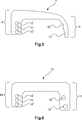
In einer besonders vorteilhaften Ausführungsform der Erfindung weist der Halterahmen ein zweites Sperrelement auf, wobei das zweite Sperrelement einseitig an der ersten Hälfte des Halterahmens fixiert ist und anderseitig mit der zweiten Hälfte des Halterahmens formschlüssig verbunden ist. Die formschlüssige Verbindung ist durch eine Bewegung des Fixierblechs, von einer Stirnfläche der zweiten Hälfte weg, lösbar. Wenn man das Sperrelement von der Stirnfläche einer Hälfte in axialer Richtung wegdrückt, wird das Sperrelement aus der formschlüssigen Verbindung gelöst. Dadurch können die beiden Hälften zumindest in zwei verschiedenen Positionen zueinander gebracht werden. In a particularly advantageous embodiment of the invention, the holding frame has a second blocking element, wherein the second blocking element is fixed on one side to the first half of the holding frame and on the other side is positively connected to the second half of the holding frame. The positive connection is by a movement of the Fixierblechs, away from an end face of the second half, solvable. If you push the locking element away from the end face of a half in the axial direction, the locking element is released from the positive connection. As a result, the two halves can be brought to each other at least in two different positions.
Vorteilhafterweise kann der Halterahmen auch zwei zweite Sperrelemente aufweisen, die sich an den jeweiligen Stirnseiten des Halterahmens befinden. Advantageously, the holding frame may also have two second locking elements, which are located on the respective end faces of the holding frame.
Damit die Fixierung über das zweite Sperrelement funktionieren kann, weist das zweite Sperrelement zumindest zwei Löcher auf und eine zugeordnete Hälfte weist zumindest einen Dorn auf, wobei der Dorn in die zumindest zwei Löcher eingreifen kann. Befindet sich der Dorn im Loch des Sperrelements welches sich im oberen Bereich des U-Bogens befindet, befindet sich der Halterahmen in einer offenen Position und kann mit Steckverbindermodulen bestückt werden. Befindet sich der Dorn in einem Loch im unteren Bereich des U-Bogens des Sperrelements, befindet sich der Halterahmen in einer geschlossenen Position. In dieser geschlossenen Position können die Steckverbindermodule nicht mehr aus dem Halterahmen herausfallen oder verrutschen. So that the fixation can work via the second blocking element, the second blocking element has at least two holes and an assigned half has at least one mandrel, wherein the mandrel can engage in the at least two holes. If the mandrel is located in the hole of the locking element which is in the upper area of the U-bend, the retaining frame is in an open position and can be equipped with connector modules. When the mandrel is in a hole in the lower portion of the barrier U-bend, the support frame is in a closed position. In this closed position, the connector modules can not fall out of the support frame or slip.
Alternativ dazu kann das zweite Sperrelement nur ein Loch enthalten und die zugeordnete Hälfte weist zumindest zwei Dorne auf, wobei die Dorne in das Loch eingreifen können. Auch mit dieser Lösung könnte eine Fixierung des Halterahmens in eine offene und eine geschlossene Position erreicht werden. Alternatively, the second locking member may include only one hole and the associated half has at least two mandrels, wherein the mandrels may engage in the hole. With this solution, a fixation of the holding frame could be achieved in an open and a closed position.
Vorteilhafterweise sind beide Hälften des Halterahmens aus einem metallischen Material gefertigt. In einem geschlossenen Zustand des Halterahmens stehen die Hälften in einem elektrisch leitenden Kontakt zueinander. Die oben erwähnte gelenkige Verbindung reicht für einen definierten elektrischen Kontakt zwischen den Halterahmen nichts aus. Über das Sperrelement werden die beiden Hälften zuverlässig in elektrischen Kontakt zueinander gebracht. Dies geschieht zum einen über das Sperrelement selbst, sofern es aus einem elektrisch leitenden Material gefertigt ist. Außerdem wird durch die Vorspannung des Sperrelements der Gelenkkopf einer Hälfte in die Gelenkaufnahme der anderen Hälfte gedrückt, wodurch ein zuverlässiger elektrischer Kontakt entsteht. Advantageously, both halves of the holding frame are made of a metallic material. In a closed state of the holding frame, the halves are in an electrically conductive contact each other. The above-mentioned articulated connection is not sufficient for a defined electrical contact between the support frame. About the blocking element, the two halves are reliably brought into electrical contact with each other. This happens on the one hand via the blocking element itself, if it is made of an electrically conductive material. In addition, is pressed by the bias of the locking element of the condyle of one half in the joint seat of the other half, whereby a reliable electrical contact is formed.
Bei der vorliegenden Erfindung werden die Begriffe offener oder geschlossener Zustand und offene oder geschlossene Position synonym verwendet. In the present invention, the terms open or closed state and open or closed position are used interchangeably.
Ausführungsbeispielembodiment
Ein Ausführungsbeispiel der Erfindung ist in den Zeichnungen dargestellt und wird im Folgenden näher erläutert. Es zeigen:An embodiment of the invention is illustrated in the drawings and will be explained in more detail below. Show it:
Die Figuren enthalten teilweise vereinfachte, schematische Darstellungen. Zum Teil werden für gleiche, aber gegebenenfalls nicht identische Elemente identische Bezugszeichen verwendet. Verschiedene Ansichten gleicher Elemente könnten unterschiedlich skaliert sein.The figures contain partially simplified, schematic representations. In part, identical reference numerals are used for the same but possibly not identical elements. Different views of the same elements could be scaled differently.
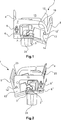
Die
An einer Stirnseite
Das Sperrelement
An einer Stirnseite
Die gegenüberliegenden Stirnseiten
Ein Schenkel
Der hier vorgestellte Halterahmen
In der Regel wird der Halterahmen in der geschlossenen Position beim Kunden angeliefert. Der Kunde wird das zweite Sperrelement
Eine Auslieferung des Halterahmens
Die geöffnete Position des Halterahmens
Mit offener Position ist gemeint, dass die Hälften entlang der Trennungslinie in einen Winkel α ungleich 180° zueinander stehen. Vorzugsweise liegt der Winkel zwischen 130° bis 170°. Ein Winkel zwischen 155° und 165° hat sich als besonders vorteilhaft erwiesen. In dieser Winkelstellung der Hälften können die Steckverbindermodule besonders leicht in den Halterahmen eingelegt werden. In der geschlossenen Position nehmen die Hälften einen Winkel von etwa 180° beziehungsweise genau 180° zueinander ein. Die Hälften stehen also in der geschlossenen Position parallel zueinander.By open position is meant that the halves along the dividing line at an angle α are not equal to 180 ° to each other. Preferably, the angle is between 130 ° to 170 °. An angle between 155 ° and 165 ° has proven to be particularly advantageous. In this angular position of the halves, the connector modules can be inserted particularly easily in the holding frame. In the closed position, the halves occupy an angle of approximately 180 ° or exactly 180 ° to each other. The halves are thus in the closed position parallel to each other.
Steckverbindermodule
Zum Einfügen der Steckverbindermodule
Anschließend werden die Rahmenhälften
Der Halterahmen
Im Folgenden wird die Erfindung noch einmal kurz zusammengefasst:
Die Erfindung betrifft einen Halterahmen (
The invention relates to a holding frame (
BezugszeichenlisteLIST OF REFERENCE NUMBERS
- 11
- Halterahmen holding frame
- 22
- Gelenkkopf joint head
- 33
- Gelenkaufnahme joint Taping
- 44
- Hälfte half
- 55
- Hälfte half
- 66
- Stirnseite front
- 77
- Erstes Sperrelement First blocking element
- 88th
- Schraube screw
- 99
- Schenkel leg
- 1010
- Öffnung opening
- 1111
- Schenkel leg
- 1212
- Aussparung recess
- 1313
- Stirnseitefront
- 1414
- Dorn mandrel
- 1515
- Zweites Sperrelement Second blocking element
- 1616
- Schenkel leg
- 1717
- Schenkel leg
- 1818
- Öffnung opening
- 1919
- Steckverbindermodul connector module
- 2020
- Halterungsmittel support means
- 21 21
- Federelastischer Rasthaken Spring-elastic latching hook
- 2222
- Seitenteil side panel
- 2323
- Ausnehmung recess
- 2424
- Erdungsbuchse ground socket
ZITATE ENTHALTEN IN DER BESCHREIBUNG QUOTES INCLUDE IN THE DESCRIPTION
Diese Liste der vom Anmelder aufgeführten Dokumente wurde automatisiert erzeugt und ist ausschließlich zur besseren Information des Lesers aufgenommen. Die Liste ist nicht Bestandteil der deutschen Patent- bzw. Gebrauchsmusteranmeldung. Das DPMA übernimmt keinerlei Haftung für etwaige Fehler oder Auslassungen.This list of the documents listed by the applicant has been generated automatically and is included solely for the better information of the reader. The list is not part of the German patent or utility model application. The DPMA assumes no liability for any errors or omissions.
Zitierte PatentliteraturCited patent literature
- DE 19707120 C1 [0003, 0004, 0050] DE 19707120 C1 [0003, 0004, 0050]
Claims (11)
Priority Applications (5)
| Application Number | Priority Date | Filing Date | Title |
|---|---|---|---|
| DE102015114697.5A DE102015114697B4 (en) | 2015-09-03 | 2015-09-03 | Holding frame for connector modules |
| CN201680051302.9A CN107925190B (en) | 2015-09-03 | 2016-08-18 | Holding frame for a plug-in connector module with a fixable locking bow |
| EP16766471.3A EP3345256B1 (en) | 2015-09-03 | 2016-08-18 | Holding frame for plug connector modules having a locking bow that can be fastened |
| US15/755,024 US10333244B2 (en) | 2015-09-03 | 2016-08-18 | Holding frame for plug connector modules having a locking bow that can be fastened |
| PCT/DE2016/100375 WO2017036450A1 (en) | 2015-09-03 | 2016-08-18 | Holding frame for plug connector modules having a locking bow that can be fastened |
Applications Claiming Priority (1)
| Application Number | Priority Date | Filing Date | Title |
|---|---|---|---|
| DE102015114697.5A DE102015114697B4 (en) | 2015-09-03 | 2015-09-03 | Holding frame for connector modules |
Publications (2)
| Publication Number | Publication Date |
|---|---|
| DE102015114697A1 true DE102015114697A1 (en) | 2017-03-09 |
| DE102015114697B4 DE102015114697B4 (en) | 2020-03-26 |
Family
ID=56939828
Family Applications (1)
| Application Number | Title | Priority Date | Filing Date |
|---|---|---|---|
| DE102015114697.5A Active DE102015114697B4 (en) | 2015-09-03 | 2015-09-03 | Holding frame for connector modules |
Country Status (5)
| Country | Link |
|---|---|
| US (1) | US10333244B2 (en) |
| EP (1) | EP3345256B1 (en) |
| CN (1) | CN107925190B (en) |
| DE (1) | DE102015114697B4 (en) |
| WO (1) | WO2017036450A1 (en) |
Families Citing this family (12)
| Publication number | Priority date | Publication date | Assignee | Title |
|---|---|---|---|---|
| CN108028491B (en) | 2015-09-03 | 2020-03-06 | 哈廷电子有限公司及两合公司 | Holding frame for a plug-in connector module |
| DE102015114703B4 (en) | 2015-09-03 | 2020-03-26 | Harting Electric Gmbh & Co. Kg | Holding frame for connector modules |
| DE102015114696B4 (en) | 2015-09-03 | 2020-10-29 | Harting Electric Gmbh & Co. Kg | Holding frame for connector modules |
| DE102015114700B4 (en) | 2015-09-03 | 2020-08-06 | Harting Electric Gmbh & Co. Kg | Holding frame |
| DE102015114701B4 (en) | 2015-09-03 | 2019-01-31 | Harting Electric Gmbh & Co. Kg | Holding frame with blocking element |
| DE102015114699A1 (en) | 2015-09-03 | 2017-03-09 | Harting Electric Gmbh & Co. Kg | Holding frame for connector modules |
| DE102016213286A1 (en) | 2016-07-20 | 2018-01-25 | Harting Electric Gmbh & Co. Kg | Multi-part holding frame, assembly and assembly process |
| DE102016213251A1 (en) * | 2016-07-20 | 2018-01-25 | Harting Electric Gmbh & Co. Kg | Holding frame arrangement with base frame and fixing element and assembly process |
| DE102017108433B4 (en) | 2017-04-20 | 2021-09-30 | Harting Electric Gmbh & Co. Kg | Holding frame for a connector and assembly method |
| DE102017108432A1 (en) | 2017-04-20 | 2018-10-25 | Harting Electric Gmbh & Co. Kg | Holding frame for a connector and method of assembly |
| DE102017129923A1 (en) * | 2017-11-24 | 2019-05-29 | Harting Electric Gmbh & Co. Kg | Grommet |
| DE102018115421A1 (en) * | 2018-06-27 | 2020-01-02 | Harting Electric Gmbh & Co. Kg | holding frame |
Citations (4)
| Publication number | Priority date | Publication date | Assignee | Title |
|---|---|---|---|---|
| DE19707120C1 (en) | 1997-02-22 | 1998-06-25 | Harting Kgaa | Mounting frame for plug-in connector modules |
| CN201656162U (en) * | 2010-03-31 | 2010-11-24 | 厦门唯恩电气有限公司 | Fixing frame for connector |
| DE202012103360U1 (en) * | 2011-10-13 | 2013-01-15 | Weidmüller Interface GmbH & Co. KG | Holding frame for connectors |
| CN204205152U (en) * | 2014-10-20 | 2015-03-11 | 宁波欧科瑞连接器有限公司 | A kind of heavy-duty connector rotary self-locking fixed frame |
Family Cites Families (43)
| Publication number | Priority date | Publication date | Assignee | Title |
|---|---|---|---|---|
| US3160280A (en) | 1963-08-12 | 1964-12-08 | Gen Electric | Device for mounting apparatus |
| FR2148699A5 (en) | 1971-07-30 | 1973-03-23 | Socapex | |
| US4693440A (en) | 1986-07-07 | 1987-09-15 | Albert Lalonde | Refreshment cup holder |
| US5529426A (en) | 1991-10-24 | 1996-06-25 | Yazaki Corporation | Housing block-retaining construction |
| JP3147221B2 (en) | 1996-02-28 | 2001-03-19 | 矢崎総業株式会社 | Movable connection structure |
| JP3235489B2 (en) | 1996-11-14 | 2001-12-04 | 住友電装株式会社 | Block connector |
| DE19745384B4 (en) | 1997-10-14 | 2005-06-30 | The Whitaker Corp., Wilmington | Electrical connector assembly |
| US6196869B1 (en) | 1998-10-30 | 2001-03-06 | Lucent Technologies Inc. | Mounting bracket and power bus for a connector block |
| US6350141B1 (en) | 2000-05-30 | 2002-02-26 | Fci Americas Technology, Inc. | Connector frame for a high density electrical connector |
| US6692310B2 (en) | 2001-11-01 | 2004-02-17 | Molex Incorporated | Modular system for stacking electrical connector assemblies |
| DE20217273U1 (en) | 2002-11-09 | 2003-01-16 | Harting Electric Gmbh & Co Kg | Fastening device for connectors |
| TWM244598U (en) * | 2003-09-26 | 2004-09-21 | Molex Taiwan Ltd | SIM card connector |
| US7056138B2 (en) | 2004-08-05 | 2006-06-06 | Tellabs Petaluma, Inc. | Retaining clip for Anderson-type power connectors |
| DE202005020026U1 (en) | 2005-12-22 | 2006-03-16 | Harting Electric Gmbh & Co. Kg | Holding frame for plug-in modules |
| JP4716123B2 (en) | 2006-06-16 | 2011-07-06 | 住友電装株式会社 | Connector cap holding structure |
| DE102007040496A1 (en) | 2007-08-21 | 2009-02-26 | Telegärtner Karl Gärtner GmbH | Cable connection device and connection device with such cable processing devices |
| CN101764314B (en) | 2008-12-23 | 2012-10-31 | 富士康(昆山)电脑接插件有限公司 | Electric connector |
| JP5615378B2 (en) | 2009-12-09 | 2014-10-29 | ハルティング エレクトリック ゲゼルシャフト ミット ベシュレンクテル ハフツング ウント コンパニー コマンディートゲゼルシャフトHARTING Electric GmbH & Co. KG | System plug connector |
| US8292676B2 (en) | 2009-12-09 | 2012-10-23 | Harting Electric Gmbh & Co. Kg | System connector with adapter module |
| DE202010002396U1 (en) * | 2010-02-16 | 2010-05-20 | Harting Electric Gmbh & Co. Kg | Electrical connector with locking bracket |
| CN101826665B (en) * | 2010-04-07 | 2011-11-16 | 辽宁省电力有限公司锦州供电公司 | Ground line device of power transmission line tower and hitching device thereof |
| US8449314B1 (en) * | 2010-12-22 | 2013-05-28 | Omnetics Connector Corporation | Latching system for electrical connector |
| CN202084755U (en) | 2011-04-28 | 2011-12-21 | 中航光电科技股份有限公司 | Connector module structure and fixed frame thereof |
| CN202335910U (en) | 2011-08-11 | 2012-07-18 | 朱君花 | Puncture lead crochet |
| DE102012110907B4 (en) | 2012-11-13 | 2019-06-13 | Harting Electric Gmbh & Co. Kg | Holding frame for holding connector modules |
| US8777676B1 (en) | 2012-12-21 | 2014-07-15 | Hubbell Incorporated | Universal mount contact block with reversible protected wiring terminals |
| US8821186B2 (en) | 2013-01-14 | 2014-09-02 | Cheng Uei Precision Industry Co., Ltd. | Universal serial bus connector |
| ITMI20130462A1 (en) | 2013-03-27 | 2014-09-28 | Westec S R L | STRUCTURE OF SUPPORTING FRAME FOR MODULAR CONNECTORS. |
| DE102013106279A1 (en) | 2013-06-17 | 2014-12-18 | Harting Electric Gmbh & Co. Kg | Holding frame for connector modules |
| DE202013103611U1 (en) | 2013-08-12 | 2013-09-19 | Harting Electric Gmbh & Co. Kg | Holding frame for connectors |
| EP3127192B1 (en) | 2014-04-02 | 2021-06-09 | Harting Electric GmbH & Co. KG | Modular plug connector |
| CN104466562B (en) | 2014-12-10 | 2017-07-21 | 资阳中车电气科技有限公司 | Connector modules fixed frame |
| CN204271392U (en) | 2014-12-10 | 2015-04-15 | 资阳南车电气有限公司 | Connector modules fixed frame |
| DE102015101433B3 (en) | 2015-02-02 | 2016-06-16 | Harting Electric Gmbh & Co. Kg | Holding frame for connector modules |
| DE102015114703B4 (en) | 2015-09-03 | 2020-03-26 | Harting Electric Gmbh & Co. Kg | Holding frame for connector modules |
| DE102015114700B4 (en) | 2015-09-03 | 2020-08-06 | Harting Electric Gmbh & Co. Kg | Holding frame |
| CN108028491B (en) | 2015-09-03 | 2020-03-06 | 哈廷电子有限公司及两合公司 | Holding frame for a plug-in connector module |
| DE102015114701B4 (en) | 2015-09-03 | 2019-01-31 | Harting Electric Gmbh & Co. Kg | Holding frame with blocking element |
| DE102015114702B4 (en) | 2015-09-03 | 2019-01-31 | Harting Electric Gmbh & Co. Kg | holding frame |
| DE102015114696B4 (en) | 2015-09-03 | 2020-10-29 | Harting Electric Gmbh & Co. Kg | Holding frame for connector modules |
| DE102015114699A1 (en) | 2015-09-03 | 2017-03-09 | Harting Electric Gmbh & Co. Kg | Holding frame for connector modules |
| DE102015216929A1 (en) * | 2015-09-03 | 2017-03-09 | Harting Electric Gmbh & Co. Kg | Holding frame for holding connector modules |
| DE102015114698A1 (en) | 2015-09-03 | 2017-03-30 | Harting Electric Gmbh & Co. Kg | Holding frame for connector modules |
-
2015
- 2015-09-03 DE DE102015114697.5A patent/DE102015114697B4/en active Active
-
2016
- 2016-08-18 US US15/755,024 patent/US10333244B2/en active Active
- 2016-08-18 CN CN201680051302.9A patent/CN107925190B/en active Active
- 2016-08-18 WO PCT/DE2016/100375 patent/WO2017036450A1/en active Application Filing
- 2016-08-18 EP EP16766471.3A patent/EP3345256B1/en active Active
Patent Citations (4)
| Publication number | Priority date | Publication date | Assignee | Title |
|---|---|---|---|---|
| DE19707120C1 (en) | 1997-02-22 | 1998-06-25 | Harting Kgaa | Mounting frame for plug-in connector modules |
| CN201656162U (en) * | 2010-03-31 | 2010-11-24 | 厦门唯恩电气有限公司 | Fixing frame for connector |
| DE202012103360U1 (en) * | 2011-10-13 | 2013-01-15 | Weidmüller Interface GmbH & Co. KG | Holding frame for connectors |
| CN204205152U (en) * | 2014-10-20 | 2015-03-11 | 宁波欧科瑞连接器有限公司 | A kind of heavy-duty connector rotary self-locking fixed frame |
Also Published As
| Publication number | Publication date |
|---|---|
| US20180254577A1 (en) | 2018-09-06 |
| EP3345256B1 (en) | 2019-10-09 |
| US10333244B2 (en) | 2019-06-25 |
| EP3345256A1 (en) | 2018-07-11 |
| CN107925190B (en) | 2020-04-07 |
| WO2017036450A1 (en) | 2017-03-09 |
| CN107925190A (en) | 2018-04-17 |
| DE102015114697B4 (en) | 2020-03-26 |
Similar Documents
| Publication | Publication Date | Title |
|---|---|---|
| DE102015114697B4 (en) | Holding frame for connector modules | |
| EP3345258B1 (en) | Support frame for connector module | |
| EP3345251B1 (en) | Fixing frame for connector with a blade shaped fixing means | |
| EP3345259B1 (en) | Support frame for connector module | |
| DE2633972C3 (en) | Arrangement for connecting two components | |
| EP3345253B1 (en) | Holding frame with restoring force for plug connector modules | |
| EP3345252B1 (en) | Holding frame comprising a fixing element held in a movable manner | |
| WO2017036439A1 (en) | Holding frame for plug connector modules | |
| DE4434202A1 (en) | Cable lead-through strip | |
| DE10256463B4 (en) | Electrical connector housing | |
| DE102009058616A1 (en) | Printed circuit board connector with locking device | |
| DE202008001842U1 (en) | plug-in device | |
| DE102014102793B4 (en) | Fastening element for a current sensor | |
| DE202014105219U1 (en) | Grounding rail device | |
| EP3406002B1 (en) | Holding frame with a guiding element for plug connector modules | |
| DE202013006032U1 (en) | Game figure for in particular a table football device | |
| DE2830640A1 (en) | TOY VEHICLE SECTION | |
| DE752837C (en) | Counter or distribution board made of molded insulating material for electrical house electricity networks. like | |
| DE102014115060B4 (en) | connecting device | |
| DE202010015841U1 (en) | connector element | |
| DE102006009905A1 (en) | shutter | |
| DE10019328A1 (en) | Clasp | |
| DE102013011224A1 (en) | Game figure for in particular a table football device | |
| DE202013102150U1 (en) | Wall feed-through terminal for an electrical conductor |
Legal Events
| Date | Code | Title | Description |
|---|---|---|---|
| R012 | Request for examination validly filed | ||
| R016 | Response to examination communication | ||
| R018 | Grant decision by examination section/examining division | ||
| R020 | Patent grant now final | ||
| R081 | Change of applicant/patentee |
Owner name: HARTING ELECTRIC STIFTUNG & CO. KG, DE Free format text: FORMER OWNER: HARTING ELECTRIC GMBH & CO. KG, 32339 ESPELKAMP, DE |