DE102015114698A1 - Holding frame for connector modules - Google Patents
Holding frame for connector modules Download PDFInfo
- Publication number
- DE102015114698A1 DE102015114698A1 DE102015114698.3A DE102015114698A DE102015114698A1 DE 102015114698 A1 DE102015114698 A1 DE 102015114698A1 DE 102015114698 A DE102015114698 A DE 102015114698A DE 102015114698 A1 DE102015114698 A1 DE 102015114698A1
- Authority
- DE
- Germany
- Prior art keywords
- finger
- holding frame
- frame
- blocking element
- halves
- Prior art date
- Legal status (The legal status is an assumption and is not a legal conclusion. Google has not performed a legal analysis and makes no representation as to the accuracy of the status listed.)
- Ceased
Links
Images

Classifications
-
- H—ELECTRICITY
- H01—ELECTRIC ELEMENTS
- H01R—ELECTRICALLY-CONDUCTIVE CONNECTIONS; STRUCTURAL ASSOCIATIONS OF A PLURALITY OF MUTUALLY-INSULATED ELECTRICAL CONNECTING ELEMENTS; COUPLING DEVICES; CURRENT COLLECTORS
- H01R13/00—Details of coupling devices of the kinds covered by groups H01R12/70 or H01R24/00 - H01R33/00
- H01R13/46—Bases; Cases
- H01R13/516—Means for holding or embracing insulating body, e.g. casing, hoods
- H01R13/518—Means for holding or embracing insulating body, e.g. casing, hoods for holding or embracing several coupling parts, e.g. frames
-
- H—ELECTRICITY
- H01—ELECTRIC ELEMENTS
- H01R—ELECTRICALLY-CONDUCTIVE CONNECTIONS; STRUCTURAL ASSOCIATIONS OF A PLURALITY OF MUTUALLY-INSULATED ELECTRICAL CONNECTING ELEMENTS; COUPLING DEVICES; CURRENT COLLECTORS
- H01R13/00—Details of coupling devices of the kinds covered by groups H01R12/70 or H01R24/00 - H01R33/00
- H01R13/46—Bases; Cases
- H01R13/502—Bases; Cases composed of different pieces
- H01R13/506—Bases; Cases composed of different pieces assembled by snap action of the parts
-
- H—ELECTRICITY
- H01—ELECTRIC ELEMENTS
- H01R—ELECTRICALLY-CONDUCTIVE CONNECTIONS; STRUCTURAL ASSOCIATIONS OF A PLURALITY OF MUTUALLY-INSULATED ELECTRICAL CONNECTING ELEMENTS; COUPLING DEVICES; CURRENT COLLECTORS
- H01R13/00—Details of coupling devices of the kinds covered by groups H01R12/70 or H01R24/00 - H01R33/00
- H01R13/46—Bases; Cases
- H01R13/502—Bases; Cases composed of different pieces
- H01R13/508—Bases; Cases composed of different pieces assembled by a separate clip or spring
-
- H—ELECTRICITY
- H01—ELECTRIC ELEMENTS
- H01R—ELECTRICALLY-CONDUCTIVE CONNECTIONS; STRUCTURAL ASSOCIATIONS OF A PLURALITY OF MUTUALLY-INSULATED ELECTRICAL CONNECTING ELEMENTS; COUPLING DEVICES; CURRENT COLLECTORS
- H01R13/00—Details of coupling devices of the kinds covered by groups H01R12/70 or H01R24/00 - H01R33/00
- H01R13/46—Bases; Cases
- H01R13/502—Bases; Cases composed of different pieces
- H01R13/512—Bases; Cases composed of different pieces assembled by screw or screws
-
- H—ELECTRICITY
- H01—ELECTRIC ELEMENTS
- H01R—ELECTRICALLY-CONDUCTIVE CONNECTIONS; STRUCTURAL ASSOCIATIONS OF A PLURALITY OF MUTUALLY-INSULATED ELECTRICAL CONNECTING ELEMENTS; COUPLING DEVICES; CURRENT COLLECTORS
- H01R13/00—Details of coupling devices of the kinds covered by groups H01R12/70 or H01R24/00 - H01R33/00
- H01R13/46—Bases; Cases
- H01R13/514—Bases; Cases composed as a modular blocks or assembly, i.e. composed of co-operating parts provided with contact members or holding contact members between them
Landscapes
- Connector Housings Or Holding Contact Members (AREA)
- Details Of Connecting Devices For Male And Female Coupling (AREA)
Abstract
Die Erfindung betrifft einen Halterahmen (1), in welchen Steckverbindermodule (19) einsetzbar sind, wobei der Halterahmen (1) aus zwei miteinander verbindbaren Hälften (4, 5) besteht, wobei der Halterahmen (1) zumindest ein erstes Sperrelement (7) aufweist und wobei die Hälften (4, 5) über das erste Sperrelement (7) in zumindest zwei Positionen zueinander ausrichtbar sind. Das Sperrelement (7) weist einen ersten Finger (25) und einen zweiten Finger (26) auf, wobei der erste Finger (25) länger ist als der zweite Finger (26) und wobei am zweiten Finger (26) endseitig ein Rasthaken (12) angeformt ist. Eine Hälfte (5) des Halterahmens (1) weist eine Aussparung (9) auf, in welche der Rasthaken (12) des zweiten Fingers (26) des Sperrelements (7) eingreifbar ist, wodurch der Halterahmen (1) in einer geöffnete Position fixierbar ist.The invention relates to a holding frame (1) in which connector modules (19) can be inserted, wherein the holding frame (1) consists of two interconnectable halves (4, 5), wherein the holding frame (1) has at least one first blocking element (7) and wherein the halves (4, 5) via the first blocking element (7) in at least two positions are aligned with each other. The locking element (7) has a first finger (25) and a second finger (26), wherein the first finger (25) is longer than the second finger (26) and wherein on the second finger (26) end a locking hook (12 ) is formed. One half (5) of the holding frame (1) has a recess (9) into which the latching hook (12) of the second finger (26) of the blocking element (7) can be engaged, whereby the holding frame (1) can be fixed in an open position is.
Description
Die Erfindung geht aus von einem Halterahmen für Steckverbindermodule nach dem Oberbegriff des unabhängigen Anspruchs 1.The invention relates to a holding frame for connector modules according to the preamble of
Derartige Halterahmen dienen zur Halterung von Steckverbindermodulen, wobei der Halterahmen mit verschiedenen Steckverbindermodulen bestückt und anschließend in ein Steckverbindergehäuse eingesetzt und mit diesem verschraubt wird. Dabei muss der Halterahmen mechanisch stabil sein, um den auftretenden Steck- und Ziehkräften beim Zusammenfügen bzw. Trennen der Steckverbindung standhalten zu können. Such support frames are used to hold connector modules, the support frame equipped with various connector modules and then inserted into a connector housing and bolted to it. In this case, the support frame must be mechanically stable in order to withstand the insertion and pulling forces occurring when assembling or disconnecting the connector can.
Stand der TechnikState of the art
Aus der
Der Halterahmen der
Bei erfolgreicher Bestückung des Halterahmens mit Steckverbindermodulen muss dieser in einen geschlossen Zustand beziehungsweise in eine geschlossene Position gebracht werden, damit die Steckverbindermodule fixiert sind. Für den geschlossenen Zustand des Halterahmens des Standes der Technik gibt es keinen fixierten geschlossenen Zustand, so dass sich der Halterahmen versehentlich öffnen kann, wodurch die Module aus ihrer Verankerung fallen können.Upon successful assembly of the holding frame with connector modules, this must be brought into a closed state or in a closed position, so that the connector modules are fixed. For the closed state of the prior art support frame, there is no fixed closed state so that the support frame may inadvertently open, allowing the modules to fall out of their anchorage.
Durch eine reine gelenkige Verbindung besteht nicht immer ein definierter elektrischer Kontakt zwischen den Hälften des Halterahmens. Dadurch kann ein zuverlässiger Einsatz des Halterahmens zu Erdungszwecken nicht gewährleistet werden. By a pure articulated connection is not always a defined electrical contact between the halves of the holding frame. As a result, a reliable use of the holding frame for grounding purposes can not be guaranteed.
Aufgabenstellungtask
Die Aufgabe der Erfindung besteht darin einen Halterahmen vorzuschlagen der einfach handhabbar und vielseitig einsetzbar ist. The object of the invention is to propose a holding frame which is easy to handle and versatile.
Die Aufgabe wird durch die kennzeichnenden Merkmale des unabhängigen Anspruchs 1 gelöst.The object is solved by the characterizing features of
Vorteilhafte Ausgestaltungen der Erfindung sind in den Unteransprüchen angegeben.Advantageous embodiments of the invention are specified in the subclaims.
Der erfindungsgemäße Halterahmen ist dazu vorgesehen mit Steckverbindermodulen gefüllt zu werden und in ein Steckverbindergehäuse oder eine Maschinenwand eingebaut und versschraubt zu werden. Der Halterahmen besteht aus zwei miteinander verbindbaren Hälften, einer ersten Hälfte und einer zweiten Hälfte, die eine Trennungsebene zueinander bilden, die parallel zu den Längsseiten der Hälften verläuft. The support frame according to the invention is intended to be filled with connector modules and installed in a connector housing or a machine wall and screwed. The support frame consists of two interconnectable halves, a first half and a second half, which form a separation plane to each other, which runs parallel to the longitudinal sides of the halves.
Der Halterahmen kann wahlweise in einer offenen Position oder in einer geschlossenen Position fixiert werden. The support frame can be selectively fixed in an open position or in a closed position.
Der Halterahmen weist zumindest ein erstes Sperrelement auf und die Hälften sind über das erste Sperrelement in zumindest zwei Positionen, eine offene Position und eine geschlossene Position, zueinander ausrichtbar und fixierbar. Die Ausrichtbarkeit wird durch die gelenkige Verbindung der beiden Hälften des Halterahmens erreicht. Die Fixierbarkeit wird durch das Sperrelement erreicht. Durch das Zusammenspiel von gelenkiger Verbindung und Fixierbarkeit in zwei Positionen wird der Halterahmen besonders bedienerfreundlich. The holding frame has at least one first blocking element and the halves can be aligned and fixed to one another via the first blocking element in at least two positions, an open position and a closed position. The alignability is achieved by the articulated connection of the two halves of the holding frame. The fixability is achieved by the blocking element. The interaction of articulated connection and fixability in two positions makes the support frame particularly user-friendly.
Mit offener Position ist gemeint, dass die Hälften entlang der Trennungslinie in einen Winkel ungleich 180° zueinander stehen. Vorzugsweise liegt der Winkel zwischen 130° bis 170°. Ein Winkel zwischen 155° und 165° hat sich als besonders vorteilhaft erwiesen. In dieser Winkelstellung der Hälften können die Steckverbindermodule besonders leicht in den Halterahmen eingelegt werden. In der geschlossenen Position nehmen die Hälften einen Winkel von etwa 180° beziehungsweise genau 180° zueinander ein. Die Hälften stehen also in der geschlossenen Position parallel zueinander. By open position is meant that the halves along the dividing line at an angle not equal to 180 ° to each other. Preferably, the angle is between 130 ° to 170 °. An angle between 155 ° and 165 ° has proven to be particularly advantageous. In this angular position of the halves, the connector modules can be inserted particularly easily in the holding frame. In the closed position, the halves occupy an angle of approximately 180 ° or exactly 180 ° to each other. The halves are thus in the closed position parallel to each other.
In einer vorteilhaften Ausführungsform der Erfindung ist das Sperrelement aus einem flachen Bauteil gebildet, welches beide Hälften des Halterahmens zumindest bereichsweise überdeckt. Das Sperrelement ist an einem Ende des Halterahmens angeordnet. Das andere Ende des Halterahmens ist sperrelementfrei ausgeführt, was den Halterahmen besonders preiswert gestaltet und einfach handhabbar macht. Das Sperrelement ist an einer Hälfte, beispielsweise über eine Schraube, fixiert. In an advantageous embodiment of the invention, the blocking element is formed from a flat component, which covers both halves of the holding frame at least partially. The blocking element is arranged at one end of the holding frame. The other end of the support frame is designed without blocking elements, which makes the support frame particularly inexpensive and easy makes it manageable. The blocking element is fixed to one half, for example via a screw.
Vorteilhafterweise weist das Sperrelement einen ersten Finger und einen zweiten Finger auf. Der erste und zweite Finger liegen innerhalb derselben Ebene. Der erste Finger ist länger als der zweite Finger ausgeführt und am zweiten Finger ist endseitig ein Rasthaken angeformt. Diese Bauform kann sehr einfach und preisgünstig, beispielsweise in Stanz-Biegetechnik, hergestellt werden. Advantageously, the blocking element has a first finger and a second finger. The first and second fingers are within the same plane. The first finger is longer than the second finger executed and the second finger end of a locking hook is formed. This design can be very simple and inexpensive, for example in stamping and bending technology, produced.
Vorzugsweise weist eine Hälfte des Halterahmens eine Aussparung auf, in welche der Rasthaken des zweiten Fingers des Sperrelements eingreifbar ist. Dadurch ist der Halterahmen in einer geöffneten Position fixierbar. Der zweite Finger hält eine Rahmenhälfte fest, so dass diese nicht wieder in die geschlossene Position fallen kann. Eine oben beschriebene Aussparung kann herstellungstechnisch leicht am Halterahmen beziehungsweise an einer Hälfte des Halterahmens realisiert werden.Preferably, one half of the holding frame has a recess into which the latching hook of the second finger of the blocking element can be engaged. As a result, the holding frame is fixable in an open position. The second finger holds a frame half so that it can not fall back into the closed position. A recess described above can be easily realized manufacturing technology on the support frame or on one half of the support frame.
Besonders vorteilhaft ist es, wenn der zweite Finger des Sperrelements beziehungsweise das Sperrelement selbst aus einem elastischen Material besteht. Durch eine vom Halterahmen weg gerichtete Bewegung des zweiten Fingers, ist der zweite Finger aus der Aussparung entfernbar und der Halterahmen ist dadurch in eine geschlossene Position bringbar. Der Rasthaken kann durch die oben beschriebene Bewegung aus der Aussparung herausgehebelt werden. Die Lösung ist sehr bedienerfreundlich. It is particularly advantageous if the second finger of the blocking element or the blocking element itself consists of an elastic material. By a directed away from the holding frame movement of the second finger, the second finger is removable from the recess and the holding frame is thereby brought into a closed position. The latching hook can be levered out of the recess by the movement described above. The solution is very user-friendly.
In einer vorteilhaften Ausführungsform der Erfindung übt der erste Finger eine Kraft auf die zweite Hälfte aus, wodurch der Halterahmen in der geschlossenen Position fixierbar ist. Die Kraft ist gegen die Drehbewegung der Gelenkachse der beiden Hälften gerichtet. Die zweite Hälfte ist durch den zweiten Finger, entgegen der Kraftwirkung der ersten Feder, in einer Winkelstellung zur ersten Hälfte fixierbar, wodurch der Halterahmen in der offenen Position fixierbar ist. In an advantageous embodiment of the invention, the first finger exerts a force on the second half, whereby the holding frame can be fixed in the closed position. The force is directed against the rotational movement of the hinge axis of the two halves. The second half is fixed by the second finger, against the force of the first spring, in an angular position to the first half, whereby the holding frame is fixed in the open position.
Vorzugsweise bestehen die Hälften aus einem metallischen Material und stehen in einem elektrisch leitenden Kontakt zueinander. Vorzugsweise kann der elektrische Kontakt über das Sperrelement hergestellt werden. Preferably, the halves are made of a metallic material and are in electrically conductive contact with each other. Preferably, the electrical contact can be made via the blocking element.
Bei der vorliegenden Erfindung werden die Begriffe offener oder geschlossener Zustand und offene oder geschlossene Position synonym verwendet. In the present invention, the terms open or closed state and open or closed position are used interchangeably.
Über das Sperrelement werden die beiden Hälften zuverlässig in elektrischen Kontakt zueinander gebracht. Dies geschieht zum einen über das Sperrelement selbst, sofern es aus einem elektrisch leitenden Material gefertigt ist. Außerdem wird durch die Vorspannung des Sperrelements der Gelenkkopf einer Hälfte in die Gelenkaufnahme der anderen Hälfte gedrückt, wodurch ein zuverlässiger elektrischer Kontakt entsteht.About the blocking element, the two halves are reliably brought into electrical contact with each other. This happens on the one hand via the blocking element itself, if it is made of an electrically conductive material. In addition, is pressed by the bias of the locking element of the condyle of one half in the joint seat of the other half, whereby a reliable electrical contact is formed.
Ausführungsbeispielembodiment
Ein Ausführungsbeispiel der Erfindung ist in den Zeichnungen dargestellt und wird im Folgenden näher erläutert. Es zeigen:An embodiment of the invention is illustrated in the drawings and will be explained in more detail below. Show it:
Die Figuren enthalten teilweise vereinfachte, schematische Darstellungen. Zum Teil werden für gleiche, aber gegebenenfalls nicht identische Elemente identische Bezugszeichen verwendet. Verschiedene Ansichten gleicher Elemente könnten unterschiedlich skaliert sein.The figures contain partially simplified, schematic representations. In part, identical reference numerals are used for the same but possibly not identical elements. Different views of the same elements could be scaled differently.
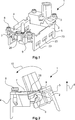
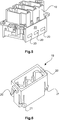
In
In
Eine Hälfte
Wird der zweite Finger
Werden die Hälften
Steckverbindermodule
Zum Einfügen der Steckverbindermodule
Anschließend werden die Rahmenhälften
Der Kern der Erfindung wird im Folgenden noch einmal kurz zusammenhängend geschildert. Es handelt sich um einen Halterahmen
BezugszeichenlisteLIST OF REFERENCE NUMBERS
- 11
- Halterahmen holding frame
- 22
- Gelenkkopf joint head
- 33
- Gelenkaufnahme joint Taping
- 44
- Hälfte half
- 55
- Hälfte half
- 66
- Pfeil arrow
- 77
- Sperrelement blocking element
- 88th
- Schraube screw
- 99
- Aussparung recess
- 1010
- Pfeilbogen bow and arrow
- 1111
- 1212
- Rasthaken latch hook
- 1313
- 1414
- 1515
- 1616
- 1717
- 1818
- 1919
- Steckverbindermodul connector module
- 2020
- Halterungsmittel support means
- 2121
- Rasthaken latch hook
- 2222
- Seitenteil side panel
- 2323
- Aussparung recess
- 2424
- 2525
- Erster Finger First finger
- 2626
- Zweiter Finger Second finger
ZITATE ENTHALTEN IN DER BESCHREIBUNG QUOTES INCLUDE IN THE DESCRIPTION
Diese Liste der vom Anmelder aufgeführten Dokumente wurde automatisiert erzeugt und ist ausschließlich zur besseren Information des Lesers aufgenommen. Die Liste ist nicht Bestandteil der deutschen Patent- bzw. Gebrauchsmusteranmeldung. Das DPMA übernimmt keinerlei Haftung für etwaige Fehler oder Auslassungen.This list of the documents listed by the applicant has been generated automatically and is included solely for the better information of the reader. The list is not part of the German patent or utility model application. The DPMA assumes no liability for any errors or omissions.
Zitierte PatentliteraturCited patent literature
- DE 19707120 C1 [0003, 0004, 0035] DE 19707120 C1 [0003, 0004, 0035]
Claims (9)
Priority Applications (5)
| Application Number | Priority Date | Filing Date | Title |
|---|---|---|---|
| DE102015114698.3A DE102015114698A1 (en) | 2015-09-03 | 2015-09-03 | Holding frame for connector modules |
| CN201680051304.8A CN108028489B (en) | 2015-09-03 | 2016-08-18 | Holding frame for a plug-in connector module with leaf spring-like fastening means |
| EP16765909.3A EP3345251B1 (en) | 2015-09-03 | 2016-08-18 | Fixing frame for connector with a blade shaped fixing means |
| PCT/DE2016/100372 WO2017036449A1 (en) | 2015-09-03 | 2016-08-18 | Holding frame for plug connector modules having a leaf-spring-type fastening means |
| US15/754,550 US10170854B2 (en) | 2015-09-03 | 2016-08-18 | Holding frame for plug connector modules having a leaf-spring-type fastening means |
Applications Claiming Priority (1)
| Application Number | Priority Date | Filing Date | Title |
|---|---|---|---|
| DE102015114698.3A DE102015114698A1 (en) | 2015-09-03 | 2015-09-03 | Holding frame for connector modules |
Publications (1)
| Publication Number | Publication Date |
|---|---|
| DE102015114698A1 true DE102015114698A1 (en) | 2017-03-30 |
Family
ID=56925930
Family Applications (1)
| Application Number | Title | Priority Date | Filing Date |
|---|---|---|---|
| DE102015114698.3A Ceased DE102015114698A1 (en) | 2015-09-03 | 2015-09-03 | Holding frame for connector modules |
Country Status (5)
| Country | Link |
|---|---|
| US (1) | US10170854B2 (en) |
| EP (1) | EP3345251B1 (en) |
| CN (1) | CN108028489B (en) |
| DE (1) | DE102015114698A1 (en) |
| WO (1) | WO2017036449A1 (en) |
Families Citing this family (9)
| Publication number | Priority date | Publication date | Assignee | Title |
|---|---|---|---|---|
| DE102015114696B4 (en) | 2015-09-03 | 2020-10-29 | Harting Electric Gmbh & Co. Kg | Holding frame for connector modules |
| DE102015114701B4 (en) | 2015-09-03 | 2019-01-31 | Harting Electric Gmbh & Co. Kg | Holding frame with blocking element |
| DE102015114697B4 (en) | 2015-09-03 | 2020-03-26 | Harting Electric Gmbh & Co. Kg | Holding frame for connector modules |
| DE102015114699A1 (en) | 2015-09-03 | 2017-03-09 | Harting Electric Gmbh & Co. Kg | Holding frame for connector modules |
| DE102015114700B4 (en) | 2015-09-03 | 2020-08-06 | Harting Electric Gmbh & Co. Kg | Holding frame |
| DE102015114703B4 (en) | 2015-09-03 | 2020-03-26 | Harting Electric Gmbh & Co. Kg | Holding frame for connector modules |
| RU2689123C1 (en) | 2015-09-03 | 2019-05-24 | Хартинг Электрик Гмбх Унд Ко. Кг | Retaining frame for plug-in connector modules |
| DE102017129742A1 (en) * | 2017-12-13 | 2019-06-13 | Harting Electric Gmbh & Co. Kg | Compact mounting housing |
| CN111755888A (en) * | 2020-07-31 | 2020-10-09 | 易快(苏州)电气科技有限公司 | Assembly connector combination frame |
Citations (4)
| Publication number | Priority date | Publication date | Assignee | Title |
|---|---|---|---|---|
| DE19707120C1 (en) | 1997-02-22 | 1998-06-25 | Harting Kgaa | Mounting frame for plug-in connector modules |
| CN201656162U (en) | 2010-03-31 | 2010-11-24 | 厦门唯恩电气有限公司 | Fixing frame for connector |
| DE202012103360U1 (en) | 2011-10-13 | 2013-01-15 | Weidmüller Interface GmbH & Co. KG | Holding frame for connectors |
| CN204205152U (en) | 2014-10-20 | 2015-03-11 | 宁波欧科瑞连接器有限公司 | A kind of heavy-duty connector rotary self-locking fixed frame |
Family Cites Families (4)
| Publication number | Priority date | Publication date | Assignee | Title |
|---|---|---|---|---|
| CN101826665B (en) * | 2010-04-07 | 2011-11-16 | 辽宁省电力有限公司锦州供电公司 | Ground line device of power transmission line tower and hitching device thereof |
| US8777676B1 (en) * | 2012-12-21 | 2014-07-15 | Hubbell Incorporated | Universal mount contact block with reversible protected wiring terminals |
| CN204271392U (en) * | 2014-12-10 | 2015-04-15 | 资阳南车电气有限公司 | Connector modules fixed frame |
| DE102015216929A1 (en) * | 2015-09-03 | 2017-03-09 | Harting Electric Gmbh & Co. Kg | Holding frame for holding connector modules |
-
2015
- 2015-09-03 DE DE102015114698.3A patent/DE102015114698A1/en not_active Ceased
-
2016
- 2016-08-18 WO PCT/DE2016/100372 patent/WO2017036449A1/en active Application Filing
- 2016-08-18 US US15/754,550 patent/US10170854B2/en active Active
- 2016-08-18 EP EP16765909.3A patent/EP3345251B1/en active Active
- 2016-08-18 CN CN201680051304.8A patent/CN108028489B/en active Active
Patent Citations (4)
| Publication number | Priority date | Publication date | Assignee | Title |
|---|---|---|---|---|
| DE19707120C1 (en) | 1997-02-22 | 1998-06-25 | Harting Kgaa | Mounting frame for plug-in connector modules |
| CN201656162U (en) | 2010-03-31 | 2010-11-24 | 厦门唯恩电气有限公司 | Fixing frame for connector |
| DE202012103360U1 (en) | 2011-10-13 | 2013-01-15 | Weidmüller Interface GmbH & Co. KG | Holding frame for connectors |
| CN204205152U (en) | 2014-10-20 | 2015-03-11 | 宁波欧科瑞连接器有限公司 | A kind of heavy-duty connector rotary self-locking fixed frame |
Also Published As
| Publication number | Publication date |
|---|---|
| EP3345251B1 (en) | 2019-06-26 |
| CN108028489A (en) | 2018-05-11 |
| CN108028489B (en) | 2020-02-28 |
| US10170854B2 (en) | 2019-01-01 |
| US20180254576A1 (en) | 2018-09-06 |
| EP3345251A1 (en) | 2018-07-11 |
| WO2017036449A1 (en) | 2017-03-09 |
Similar Documents
| Publication | Publication Date | Title |
|---|---|---|
| DE102015114703B4 (en) | Holding frame for connector modules | |
| EP3345251B1 (en) | Fixing frame for connector with a blade shaped fixing means | |
| EP3345256B1 (en) | Holding frame for plug connector modules having a locking bow that can be fastened | |
| EP3345253B1 (en) | Holding frame with restoring force for plug connector modules | |
| DE102015114696B4 (en) | Holding frame for connector modules | |
| DE102017108430B4 (en) | Holding frame for a heavy connector and system | |
| EP2339701B1 (en) | Circuit board connector with locking device | |
| EP3345257A1 (en) | Holding frame for plug connector modules | |
| EP3345252B1 (en) | Holding frame comprising a fixing element held in a movable manner | |
| CH667553A5 (en) | SCREWLESS ELECTRICAL TERMINAL. | |
| DE202017107144U1 (en) | Set of connector and retaining element and connector and retaining element for this purpose | |
| EP3114361A1 (en) | Fastening element for a current sensor | |
| DE69701707T2 (en) | Device for fastening an electrical device | |
| DE102018119525A1 (en) | Tap connector and protective ground contact thereto | |
| DE19600236B4 (en) | Housing element of an electrical connector | |
| DE102018206849A1 (en) | Device for clamping attachment | |
| DE102017129742A1 (en) | Compact mounting housing | |
| AT404646B (en) | DEVICE FOR PREVENTING TOUCHING TERMINALS OF SWITCHGEAR | |
| DE202010009768U1 (en) | Plug housing for receiving plug-in elements | |
| DE2460350A1 (en) | Snap-action hinge for electric appts. cover flap - has metal strip or angled wire with opposing end hooks engaging inset spindles |
Legal Events
| Date | Code | Title | Description |
|---|---|---|---|
| R012 | Request for examination validly filed | ||
| R002 | Refusal decision in examination/registration proceedings | ||
| R003 | Refusal decision now final |