DE102012205576A1 - Method for providing the clamping force generated by a parking brake - Google Patents
Method for providing the clamping force generated by a parking brake Download PDFInfo
- Publication number
- DE102012205576A1 DE102012205576A1 DE102012205576A DE102012205576A DE102012205576A1 DE 102012205576 A1 DE102012205576 A1 DE 102012205576A1 DE 102012205576 A DE102012205576 A DE 102012205576A DE 102012205576 A DE102012205576 A DE 102012205576A DE 102012205576 A1 DE102012205576 A1 DE 102012205576A1
- Authority
- DE
- Germany
- Prior art keywords
- motor
- brake
- current
- clamping force
- phase
- Prior art date
- Legal status (The legal status is an assumption and is not a legal conclusion. Google has not performed a legal analysis and makes no representation as to the accuracy of the status listed.)
- Pending
Links
Images

Classifications
-
- B—PERFORMING OPERATIONS; TRANSPORTING
- B60—VEHICLES IN GENERAL
- B60T—VEHICLE BRAKE CONTROL SYSTEMS OR PARTS THEREOF; BRAKE CONTROL SYSTEMS OR PARTS THEREOF, IN GENERAL; ARRANGEMENT OF BRAKING ELEMENTS ON VEHICLES IN GENERAL; PORTABLE DEVICES FOR PREVENTING UNWANTED MOVEMENT OF VEHICLES; VEHICLE MODIFICATIONS TO FACILITATE COOLING OF BRAKES
- B60T13/00—Transmitting braking action from initiating means to ultimate brake actuator with power assistance or drive; Brake systems incorporating such transmitting means, e.g. air-pressure brake systems
- B60T13/10—Transmitting braking action from initiating means to ultimate brake actuator with power assistance or drive; Brake systems incorporating such transmitting means, e.g. air-pressure brake systems with fluid assistance, drive, or release
- B60T13/66—Electrical control in fluid-pressure brake systems
- B60T13/662—Electrical control in fluid-pressure brake systems characterised by specified functions of the control system components
-
- B—PERFORMING OPERATIONS; TRANSPORTING
- B60—VEHICLES IN GENERAL
- B60T—VEHICLE BRAKE CONTROL SYSTEMS OR PARTS THEREOF; BRAKE CONTROL SYSTEMS OR PARTS THEREOF, IN GENERAL; ARRANGEMENT OF BRAKING ELEMENTS ON VEHICLES IN GENERAL; PORTABLE DEVICES FOR PREVENTING UNWANTED MOVEMENT OF VEHICLES; VEHICLE MODIFICATIONS TO FACILITATE COOLING OF BRAKES
- B60T13/00—Transmitting braking action from initiating means to ultimate brake actuator with power assistance or drive; Brake systems incorporating such transmitting means, e.g. air-pressure brake systems
- B60T13/74—Transmitting braking action from initiating means to ultimate brake actuator with power assistance or drive; Brake systems incorporating such transmitting means, e.g. air-pressure brake systems with electrical assistance or drive
- B60T13/741—Transmitting braking action from initiating means to ultimate brake actuator with power assistance or drive; Brake systems incorporating such transmitting means, e.g. air-pressure brake systems with electrical assistance or drive acting on an ultimate actuator
-
- F—MECHANICAL ENGINEERING; LIGHTING; HEATING; WEAPONS; BLASTING
- F16—ENGINEERING ELEMENTS AND UNITS; GENERAL MEASURES FOR PRODUCING AND MAINTAINING EFFECTIVE FUNCTIONING OF MACHINES OR INSTALLATIONS; THERMAL INSULATION IN GENERAL
- F16D—COUPLINGS FOR TRANSMITTING ROTATION; CLUTCHES; BRAKES
- F16D65/00—Parts or details
- F16D65/14—Actuating mechanisms for brakes; Means for initiating operation at a predetermined position
- F16D65/16—Actuating mechanisms for brakes; Means for initiating operation at a predetermined position arranged in or on the brake
- F16D65/18—Actuating mechanisms for brakes; Means for initiating operation at a predetermined position arranged in or on the brake adapted for drawing members together, e.g. for disc brakes
-
- F—MECHANICAL ENGINEERING; LIGHTING; HEATING; WEAPONS; BLASTING
- F16—ENGINEERING ELEMENTS AND UNITS; GENERAL MEASURES FOR PRODUCING AND MAINTAINING EFFECTIVE FUNCTIONING OF MACHINES OR INSTALLATIONS; THERMAL INSULATION IN GENERAL
- F16D—COUPLINGS FOR TRANSMITTING ROTATION; CLUTCHES; BRAKES
- F16D2121/00—Type of actuator operation force
- F16D2121/02—Fluid pressure
- F16D2121/04—Fluid pressure acting on a piston-type actuator, e.g. for liquid pressure
-
- F—MECHANICAL ENGINEERING; LIGHTING; HEATING; WEAPONS; BLASTING
- F16—ENGINEERING ELEMENTS AND UNITS; GENERAL MEASURES FOR PRODUCING AND MAINTAINING EFFECTIVE FUNCTIONING OF MACHINES OR INSTALLATIONS; THERMAL INSULATION IN GENERAL
- F16D—COUPLINGS FOR TRANSMITTING ROTATION; CLUTCHES; BRAKES
- F16D2121/00—Type of actuator operation force
- F16D2121/18—Electric or magnetic
- F16D2121/24—Electric or magnetic using motors
-
- F—MECHANICAL ENGINEERING; LIGHTING; HEATING; WEAPONS; BLASTING
- F16—ENGINEERING ELEMENTS AND UNITS; GENERAL MEASURES FOR PRODUCING AND MAINTAINING EFFECTIVE FUNCTIONING OF MACHINES OR INSTALLATIONS; THERMAL INSULATION IN GENERAL
- F16D—COUPLINGS FOR TRANSMITTING ROTATION; CLUTCHES; BRAKES
- F16D2123/00—Multiple operation forces
Abstract
Bei einem Verfahren zum Bereitstellen der von einem elektrischen Bremsmotor in einer Feststellbremse erzeugten Klemmkraft wird die Klemmkraft als Funktion der Motorkonstanten des Bremsmotors unter Zugrundelegung von aktuellen Messwerten des Motorstroms und der Motorspannung bestimmt.In a method for providing the clamping force generated by an electric brake motor in a parking brake, the clamping force is determined as a function of the motor constant of the brake motor based on current measurements of the motor current and the motor voltage.
Description
Die Erfindung bezieht sich auf ein Verfahren zum Bereitstellen der von einer Feststellbremse in einem Fahrzeug erzeugten Klemmkraft.The invention relates to a method for providing the clamping force generated by a parking brake in a vehicle.
Stand der TechnikState of the art
Aus der
Um die Klemmkraft möglichst genau bestimmen zu können, muss die Motorkonstante des elektrischen Bremsmotors bekannt sein, deren Wert Fertigungstoleranzen unterliegt und außerdem alterungs- und temperaturbedingt schwanken kann.In order to determine the clamping force as accurately as possible, the motor constant of the electric brake motor must be known, the value of which is subject to manufacturing tolerances and may also vary due to aging and temperature.
Offenbarung der ErfindungDisclosure of the invention
Der Erfindung liegt die Aufgabe zu Grunde, mit einfachen Maßnahmen die Klemmkraft in einer Feststellbremse, welche einen elektrischen Bremsmotor aufweist, mit hoher Genauigkeit bereitzustellen.The invention is based on the object with simple measures to provide the clamping force in a parking brake, which has an electric brake motor, with high accuracy.
Diese Aufgabe wird mit den Merkmalen des Anspruches 1 gelöst. Die Unteransprüche geben zweckmäßige Weiterbildungen an.This object is achieved with the features of claim 1. The dependent claims indicate expedient developments.
Das erfindungsgemäße Verfahren bezieht sich auf elektromechanische Feststellbremsen in Fahrzeugen, über die eine das Fahrzeug im Stillstand festsetzende Klemmkraft erzeugbar ist. Die Feststellbremse weist einen elektrischen Bremsmotor auf, über den auf elektromechanischem Wege die Klemmkraft generiert wird. Bei einer Betätigung des Bremsmotors wird ein Bremskolben, der Träger eines Bremsbelages ist, gegen eine Bremsscheibe gedrückt. Die Feststellbremse kann ggf. mit einer Zusatzbremseinrichtung ausgestattet sein, um ergänzend eine Zusatzklemmkraft zu erzeugen, so dass sich die Gesamtklemmkraft aus dem elektromechanisch vom Bremsmotor gestellten Anteil und der Zusatzklemmkraft zusammensetzt. Bei der Zusatzbremseinrichtung handelt es sich beispielsweise um eine hydraulische Bremseinrichtung, insbesondere die hydraulische Fahrzeugbremse, über die im regulären Fahrbetrieb eine das Fahrzeug abbremsende Bremskraft erzeugt wird. Der hydraulische Druck wirkt hierbei auf den Bremskolben.The method according to the invention relates to electromechanical parking brakes in vehicles, via which a clamping force fixing the vehicle at a standstill can be generated. The parking brake has an electric brake motor, via which the clamping force is generated by electromechanical means. Upon actuation of the brake motor, a brake piston which is the carrier of a brake lining is pressed against a brake disk. The parking brake may optionally be equipped with an additional brake device to additionally generate an additional clamping force, so that the total clamping force from the electromechanically provided by the brake motor share and the additional clamping force composed. The auxiliary brake device is, for example, a hydraulic brake device, in particular the hydraulic vehicle brake, by means of which a braking force braking the vehicle is generated during regular driving operation. The hydraulic pressure acts on the brake piston.
Beim erfindungsgemäßen Verfahren wird die Motorkonstante des elektrischen Bremsmotors, die zur Ermittlung der Klemmkraft wesentlich ist, aus aktuellen Messwerten des Motorstroms und der Motorspannung ermittelt. Die Messwerte werden während einer Betätigung des Bremsmotors gemessen. Es werden der Leerlaufstrom und die Leerlaufspannung während einer Leerlaufphase des Bremsmotors und der Motorstrom während einer dynamischen Stromänderungsphase ermittelt. Damit stehen ausreichend Informationen zur Verfügung, um den aktuellen Wert der Motorkonstanten berechnen zu können. Die Motorkonstante ist temperatur- und alterungsabhängig, außerdem unterliegt der an sich bekannte Wert der Motorkonstanten Fertigungstoleranzen. Die Motorkonstante kann über die Messwerte von Motorstrom und Motorspannung mit hoher Genauigkeit bestimmt werden, außerdem kann die Klemmkraft mit einer entsprechend hohen Genauigkeit berechnet werden. Hierbei wird zunächst das Motorlastmoment und daraus unter Berücksichtigung der Getriebeuntersetzung die wirksame Klemmkraft errechnet. Als Messgrößen genügen grundsätzlich der Strom und die Spannung im elektrischen Bremsmotor.In the method according to the invention, the motor constant of the electric brake motor, which is essential for determining the clamping force, is determined from current measured values of the motor current and the motor voltage. The measured values are measured during an actuation of the brake motor. The idling current and the open circuit voltage during an idling phase of the brake motor and the motor current during a dynamic current change phase are determined. This provides sufficient information to calculate the current value of the motor constant. The motor constant is dependent on temperature and age, in addition, the known value of the motor constant is subject to manufacturing tolerances. The motor constant can be determined with high accuracy via the measured values of motor current and motor voltage. In addition, the clamping force can be calculated with a correspondingly high degree of accuracy. In this case, first the engine load torque and from this, taking into account the gear reduction, the effective clamping force is calculated. The measured quantities are basically the current and the voltage in the electric brake motor.
In der Leerlaufphase des Bremsmotors können der Leerlaufstrom und die Leerlaufspannung mit hoher Genauigkeit ermittelt werden. Die Leerlaufphase liegt vor, wenn der Betrag des Gradienten des Motorstroms bzw. der Motorspannung zumindest annähernd gleich null ist bzw. einen zugeordneten Schwellenwert unterschreitet. In der dynamischen Stromänderungsphase werden dagegen zweckmäßigerweise mehrere Strommesswerte ermittelt und der Berechnung der Motorkonstanten zu Grunde gelegt. Damit liegt eine ausreichend große Datenbasis vor, um mit hoher Verlässlichkeit und Genauigkeit die Motorkonstante bestimmen zu können.In the idling phase of the brake motor, the no-load current and the open-circuit voltage can be determined with high accuracy. The idling phase occurs when the magnitude of the gradient of the motor current or the motor voltage is at least approximately equal to zero or falls below an associated threshold value. By contrast, in the dynamic current change phase, a plurality of current measured values are expediently determined and the calculation of the motor constant is used as a basis. This provides a sufficiently large database to be able to determine the motor constant with high reliability and accuracy.
Gemäß einer vorteilhaften Ausführung werden die Messwerte während eines Zuspannvorgangs des Bremsmotors, also beim Erzeugen einer elektromechanischen Klemmkraft ermittelt. Während des Zuspannvorgangs können verschiedene Phasen unterschieden werden, u.a. eine Startphase mit hoher Dynamik im Stromverlauf und eine sich daran anschließende Leerlaufphase mit zumindest annähernd konstantem Motorstrom und konstanter Motorspannung. Als dynamische Stromänderungsphase wird insbesondere die Anfangsphase nach dem Einschalten des Bremsmotors herangezogen, wohingegen die Leerlaufphase sich an die Anfangsphase anschließt. Grundsätzlich ist es aber auch möglich, die Strom- und Spannungswerte auch während einer sonstigen Betätigungsphase des elektrischen Bremsmotors zu bestimmen, insbesondere während der Lösephase.According to an advantageous embodiment, the measured values are determined during an application process of the brake motor, that is to say when an electromechanical clamping force is generated. During the application process, different phases can be distinguished, including a starting phase with high dynamics in the course of the current and an adjoining idling phase with at least approximately constant motor current and constant motor voltage. In particular, the initial phase after switching on the brake motor is used as the dynamic current change phase, whereas the idle phase follows the initial phase. In principle, it is also possible, the current and voltage values during another operating phase of the electrical Brake motor to determine, especially during the release phase.
Zweckmäßigerweise wird die Motorkonstante in einem rekursiven Algorithmus berechnet, beispielsweise unter Zugrundelegung der Methode der kleinsten Fehlerquadrate. Während der Stromänderungsphase werden mehrere Stromwerte gemessen, die dem rekursiven Algorithmus zu Grunde gelegt werden. Bei einer ausreichend großen Anzahl an Messwerten können Parameter bestimmt werden, die der Berechnung der Motorkonstanten zu Grunde gelegt werden können.The motor constant is expediently calculated in a recursive algorithm, for example using the least squares method. During the power change phase, several current values are measured based on the recursive algorithm. With a sufficiently large number of measured values, parameters can be determined which can be used to calculate the motor constants.
Die Motorkonstante hängt vom Gesamtwiderstand zwischen der Spannungsquelle und dem Motor ab. Dieser Gesamtwiderstand, der sich additiv aus dem Motorwiderstand und den Leitungswiderständen zusammensetzt, kann als Funktion von Leerlaufspannung und Leerlaufstrom sowie eines ersten Parameters ermittelt werden. Anschließend wird die Motorkonstante unter Berücksichtigung des Gesamtwiderstandes und eines zweiten Parameters berechnet, wobei die ersten und zweiten Parameter in einem rekursiven Algorithmus aus den aktuellen Stromwerten während der dynamischen Stromänderungsphase berechnet werden.The motor constant depends on the total resistance between the voltage source and the motor. This total resistance, which is composed of the motor resistance and the line resistances additively, can be determined as a function of no-load voltage and no-load current as well as a first parameter. Subsequently, the motor constant is calculated considering the total resistance and a second parameter, wherein the first and second parameters are calculated in a recursive algorithm from the current current values during the dynamic current change phase.
Die Motorkonstante und die aktuell vom elektrischen Bremsmotor gestellte Klemmkraft kann beispielsweise während jeder Betätigung des Bremsmotors, insbesondere zum Erzeugen einer Klemmkraft ermittelt werden. Während des Zuspannvorganges werden die dynamischen Stromwerte, welche unmittelbar nach dem Einschalten des Stroms stark abfallen, gemessen und zwischengespeichert. In der anschließenden Leerlaufphase werden der Leerlaufstrom und die Leerlaufspannung ermittelt und anschließend der rekursive Algorithmus zum Bestimmen der Hilfsvariablen bzw. Parameter durchlaufen, welche der Berechnung des Gesamtwiderstandes und der Motorkonstanten zu Grunde gelegt werden. Bei Kenntnis der Motorkonstanten kann das aktuelle Motorlastmoment und daraus die Klemmkraft bestimmt werden.The motor constant and the clamping force currently provided by the electric brake motor can be determined, for example, during each actuation of the brake motor, in particular for generating a clamping force. During the application process, the dynamic current values, which drop sharply immediately after the current is switched on, are measured and buffered. In the subsequent idling phase, the no-load current and the open-circuit voltage are determined, and then the recursive algorithm for determining the auxiliary variables or parameters, which are used as the basis for calculating the total resistance and the motor constants, is run through. With knowledge of the motor constants, the current engine load torque and from it the clamping force can be determined.
Das erfindungsgemäße Verfahren läuft in einem Regel- bzw. Steuergerät im Fahrzeug ab, das Bestandteil der Feststellbremse sein kann.The inventive method runs in a control or control unit in the vehicle, which may be part of the parking brake.
Weitere Vorteile und zweckmäßige Ausführungen sind den weiteren Ansprüchen, der Figurenbeschreibung und den Zeichnungen zu entnehmen. Es zeigen:Further advantages and expedient embodiments can be taken from the further claims, the description of the figures and the drawings. Show it:
Das Spindelbauteil
Auf den Bremskolben wirkt außerdem der hydraulische Druck der regulären, hydraulischen Fahrzeugbremse, mit der das Fahrzeug während der Fahrt abgebremst wird. Der hydraulische Druck kann auch im Fahrzeugstillstand bei Betätigung der Feststellbremse unterstützend wirksam sein, so dass sich die Gesamt-Klemmkraft aus dem elektromotorisch gestellten Anteil und dem hydraulischen Anteil zusammensetzt. On the brake piston also acts the hydraulic pressure of the regular, hydraulic vehicle brake, with which the vehicle is braked while driving. The hydraulic pressure can also be effective in the vehicle standstill upon actuation of the parking brake, so that the total clamping force composed of the electromotive component and the hydraulic component.
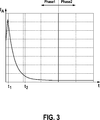
In
In der Phase 4 wirkt zusätzlich der hydraulische Druck p der Fahrzeugbremse auf den Bremskolben, so dass die gesamte Klemmkraft FKl sich aus dem vom elektrischen Bremsmotor gestellten Klemmkraftanteil und dem hydraulischen Anteil additiv zusammensetzt. Am Ende von Phase 4 erfolgt das Abschalten des elektrischen Bremsmotors durch Öffnen des Stromkreises, außerdem wird der Pumpenmotor der hydraulischen Fahrzeugbremse abgeschaltet. Demzufolge fallen der hydraulische Druck p, der Strom I, die Spannung U und die Drehzahl ω des Bremsmotors
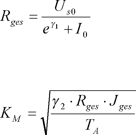
Um beim Zuspannvorgang den aktuellen Wert der erzeugten Klemmkraft mit hoher Genauigkeit zu bestimmen, wird zunächst die Motorkonstante KM ermittelt, aus der gemäß eines bekannten, funktionalen Zusammenhangs die Klemmkraft FKl berechnet werden kann:
Die Motorkonstante KM kann als Funktion des Gesamtwiderstandes Rges, welcher sich aus der Summe der Einzelwiderstände von Bremsmotor und Leitungen zum Bremsmotor zusammensetzt, unter Berücksichtigung des Massenträgheitsmomentes Jges des Bremsmotors einschließlich einer nachgeschalteten Getriebeeinheit und einer Abtastzeit TA sowie eines Parameters bzw. einer Hilfsgröße γ2 gemäß der Beziehung ![]()
![]()
![]()
![]()
In
In der Phase 1 stellt der Zeitraum zwischen den Zeitpunkten t1 und t2 eine dynamische Stromänderungsphase dar, die durch einen hohen Stromgradienten gekennzeichnet ist. Der Startzeitpunkt t1 und der Endzeitpunkt t2 können variabel festgelegt werden anhand zugeordneter Gradienten-Schwellenwerte für den Motorstrom. Die Auswertung der Messwerte beginnt, wenn zum Startzeitpunkt t1 der Stromgradient einen negativen Schwellenwert unterschreitet. Die Auswertung endet zum Endzeitpunkt t2, wenn der Stromgradient einen zweiten Schwellenwert überschreitet, wobei der Betrag des zweiten Schwellenwertes kleiner ist als der Betrag des ersten Schwellenwertes.In phase 1, the time period between times t 1 and t 2 represents a dynamic current change phase, which is characterized by a high current gradient. The start time t 1 and the end time t 2 can be set variably using assigned gradient threshold values for the motor current. The evaluation of the measured values begins when, at the start time t 1, the current gradient falls below a negative threshold value. The evaluation ends at the end time t 2 when the current gradient exceeds a second threshold, the magnitude of the second threshold being less than the magnitude of the first threshold.
Phase 2 ist die Leerlaufphase des Bremsmotors, in welcher der Stromgradient zumindest annähernd gleich null ist. In dieser Phase wird zumindest ein Messwert jeweils zur Bestimmung des Leerlaufstromes I0 und der Leerlaufspannung Us0 bestimmt. Der Zeitpunkt zur Messung hängt vom Gradienten des Stroms bzw. der Spannung ab. Unterschreitet der Gradient einen zugeordneten Schwellenwert, wird die Messung bzw. die Auswertung durchgeführt.
Damit liegen auf der Grundlage von Strom- und Spannungsmessungen während des Zuspannvorganges des elektrischen Bremsmotors alle Informationen vor, um die aktuell wirkende Klemmkraft mit hoher Genauigkeit bestimmen zu können.Thus, all information is present on the basis of current and voltage measurements during the application process of the electric brake motor in order to be able to determine the currently acting clamping force with high accuracy.
ZITATE ENTHALTEN IN DER BESCHREIBUNG QUOTES INCLUDE IN THE DESCRIPTION
Diese Liste der vom Anmelder aufgeführten Dokumente wurde automatisiert erzeugt und ist ausschließlich zur besseren Information des Lesers aufgenommen. Die Liste ist nicht Bestandteil der deutschen Patent- bzw. Gebrauchsmusteranmeldung. Das DPMA übernimmt keinerlei Haftung für etwaige Fehler oder Auslassungen.This list of the documents listed by the applicant has been generated automatically and is included solely for the better information of the reader. The list is not part of the German patent or utility model application. The DPMA assumes no liability for any errors or omissions.
Zitierte PatentliteraturCited patent literature
- DE 102006052810 A1 [0002] DE 102006052810 A1 [0002]
Claims (9)
Priority Applications (5)
| Application Number | Priority Date | Filing Date | Title |
|---|---|---|---|
| DE102012205576A DE102012205576A1 (en) | 2012-04-04 | 2012-04-04 | Method for providing the clamping force generated by a parking brake |
| JP2015502155A JP5919431B2 (en) | 2012-04-04 | 2013-02-08 | Method for supplying a clamping force generated by a parking brake |
| PCT/EP2013/052503 WO2013149743A1 (en) | 2012-04-04 | 2013-02-08 | Method for providing the clamping force generated by a parking brake |
| KR1020147027651A KR101981829B1 (en) | 2012-04-04 | 2013-02-08 | Method for providing the clamping force generated by a parking brake |
| US14/389,569 US9643583B2 (en) | 2012-04-04 | 2013-02-08 | Method for providing the clamping force generated by a parking brake |
Applications Claiming Priority (1)
| Application Number | Priority Date | Filing Date | Title |
|---|---|---|---|
| DE102012205576A DE102012205576A1 (en) | 2012-04-04 | 2012-04-04 | Method for providing the clamping force generated by a parking brake |
Publications (1)
| Publication Number | Publication Date |
|---|---|
| DE102012205576A1 true DE102012205576A1 (en) | 2013-10-10 |
Family
ID=47683730
Family Applications (1)
| Application Number | Title | Priority Date | Filing Date |
|---|---|---|---|
| DE102012205576A Pending DE102012205576A1 (en) | 2012-04-04 | 2012-04-04 | Method for providing the clamping force generated by a parking brake |
Country Status (5)
| Country | Link |
|---|---|
| US (1) | US9643583B2 (en) |
| JP (1) | JP5919431B2 (en) |
| KR (1) | KR101981829B1 (en) |
| DE (1) | DE102012205576A1 (en) |
| WO (1) | WO2013149743A1 (en) |
Cited By (16)
| Publication number | Priority date | Publication date | Assignee | Title |
|---|---|---|---|---|
| WO2014170259A2 (en) * | 2013-04-15 | 2014-10-23 | Ve Vienna Engineering Forschungs- Und Entwicklungs Gmbh | Method for actuating an electrically actuated friction brake |
| WO2016034314A1 (en) * | 2014-09-01 | 2016-03-10 | Robert Bosch Gmbh | Braking device for a motor vehicle, and method for controlling the braking device |
| US20160103430A1 (en) * | 2014-10-14 | 2016-04-14 | Robert Bosch Gmbh | Method and Device for Operating a Braking Device, Braking Device |
| DE102015201556A1 (en) | 2015-01-29 | 2016-08-04 | Robert Bosch Gmbh | Method and device for operating a braking device, braking device |
| WO2016188910A1 (en) * | 2015-05-22 | 2016-12-01 | Robert Bosch Gmbh | Method for providing a brake force in a vehicle |
| DE102015211468A1 (en) | 2015-06-22 | 2016-12-22 | Robert Bosch Gmbh | Method for determining the travel in an electromechanical brake device |
| DE102015218411B3 (en) * | 2015-09-24 | 2017-02-02 | Siemens Aktiengesellschaft | Positioning method for a parking brake |
| EP3156294A1 (en) * | 2015-10-14 | 2017-04-19 | Akebono Brake Industry Co., Ltd. | Method for controlling a parking brake system |
| DE102015224720A1 (en) | 2015-12-09 | 2017-06-14 | Robert Bosch Gmbh | Method for operating a brake device, control device for such a brake device, brake device, and vehicle with such a brake device |
| WO2017202526A1 (en) * | 2016-05-24 | 2017-11-30 | Robert Bosch Gmbh | Method for monitoring the braking force in a vehicle |
| WO2017216230A1 (en) * | 2016-06-16 | 2017-12-21 | Valeo Siemens Eautomotive Germany Gmbh | Parking brake and operating method |
| WO2018046296A1 (en) * | 2016-09-08 | 2018-03-15 | Lucas Automotive Gmbh | Technique for characterising an electromechanical actuator unit for a vehicle brake |
| DE102017211176A1 (en) | 2017-06-30 | 2019-01-03 | Robert Bosch Gmbh | Method for operating a brake system of a motor vehicle, and control and regulating device |
| DE102020200495A1 (en) | 2020-01-16 | 2021-07-22 | Robert Bosch Gesellschaft mit beschränkter Haftung | Brake system for a motor vehicle, method for operating a brake system and a plurality of control units for a brake system of a motor vehicle |
| DE102020200494A1 (en) | 2020-01-16 | 2021-07-22 | Robert Bosch Gesellschaft mit beschränkter Haftung | Brake system, a plurality of control units for a brake system, as well as a method for operating a brake system |
| WO2023072351A1 (en) * | 2021-11-01 | 2023-05-04 | Continental Automotive Technologies GmbH | Method for electronic air gap control of a motor vehicle wheel brake and electronic motor vehicle braking system for same |
Families Citing this family (12)
| Publication number | Priority date | Publication date | Assignee | Title |
|---|---|---|---|---|
| DE102009028505A1 (en) * | 2009-08-13 | 2011-02-17 | Robert Bosch Gmbh | Method for adjusting the clamping force of a hydraulically assisted electromotive parking brake |
| JP5880523B2 (en) * | 2013-11-15 | 2016-03-09 | トヨタ自動車株式会社 | Control device for electric parking brake |
| DE102015206034A1 (en) * | 2015-04-02 | 2016-10-06 | Robert Bosch Gmbh | Method and device for operating a braking system of a vehicle, braking system |
| DE102016205298A1 (en) * | 2016-03-31 | 2017-10-05 | Robert Bosch Gmbh | Method for providing a braking force in a vehicle |
| US9995354B2 (en) | 2016-07-21 | 2018-06-12 | Goodrich Corporation | Systems and methods for clamping force estimation in electromechanical brake systems |
| KR20180047998A (en) | 2016-11-02 | 2018-05-10 | 주식회사 만도 | electronic parking brake system and control method thereof |
| JP6811101B2 (en) * | 2017-01-23 | 2021-01-13 | 日立オートモティブシステムズ株式会社 | Electric parking brake device and brake device |
| JP7136662B2 (en) * | 2018-11-01 | 2022-09-13 | 日立Astemo株式会社 | electric parking brake device |
| CN111146902A (en) * | 2018-11-03 | 2020-05-12 | 达尼克有限责任公司 | Electromechanical drive device, brake system and battery management system |
| US11912156B2 (en) * | 2019-10-07 | 2024-02-27 | Ddanigo Llc | Electromechanical drive apparatus, braking systems, and battery management systems |
| KR20210065717A (en) | 2019-11-27 | 2021-06-04 | 주식회사 만도 | Electronic parking brake system and control method thereof |
| JP7286560B2 (en) | 2020-01-21 | 2023-06-05 | 日立Astemo株式会社 | ELECTRIC PARKING BRAKE DEVICE AND ELECTRIC PARKING BRAKE CONTROL METHOD |
Citations (1)
| Publication number | Priority date | Publication date | Assignee | Title |
|---|---|---|---|---|
| DE102006052810A1 (en) | 2006-11-09 | 2008-05-15 | Robert Bosch Gmbh | Electromechanical actuator's force development estimating method for hand brake of motor vehicle, involves considering consumed current or rotational speed of motor i.e. direct current motor, during estimation of supply voltage value |
Family Cites Families (31)
| Publication number | Priority date | Publication date | Assignee | Title |
|---|---|---|---|---|
| US2682630A (en) * | 1951-05-01 | 1954-06-29 | Bbc Brown Boveri & Cie | Speed regulating system for direct current motors |
| US3937974A (en) * | 1974-08-30 | 1976-02-10 | General Electric Company | Starter-generator utilizing phase controlled rectifiers to drive a dynamoelectric machine as a brushless DC motor in the starting mode with starter position sense variation with speed |
| FR2600136B1 (en) * | 1986-06-12 | 1988-09-09 | Bendix France | AUTOMATICALLY ADJUSTABLE BRAKE MOTOR |
| US5161650A (en) * | 1991-05-22 | 1992-11-10 | Allied-Signal Inc. | Disc brake with powered integral parking mechanism |
| US6311808B1 (en) * | 1996-02-09 | 2001-11-06 | Continental Teves Ag & Co., Ohg | Combined service and parking brake system |
| DE19849334B4 (en) * | 1998-10-26 | 2013-03-14 | Linde Material Handling Gmbh | Hydrostatic motor unit |
| DE10080921D2 (en) * | 1999-04-13 | 2002-04-11 | Continental Teves Ag & Co Ohg | Part brake disc brake with electromechanical actuation unit |
| US6959794B2 (en) * | 2003-05-30 | 2005-11-01 | Goodrich Corporation | Low power parking brake force adjustment apparatus and method for electrically actuated brake systems |
| DE10357374A1 (en) * | 2003-12-09 | 2005-07-14 | Knorr-Bremse Systeme für Nutzfahrzeuge GmbH | Disc brake, in particular with electromotive adjusting device, and method for controlling such disc brakes |
| US7673950B2 (en) * | 2004-11-04 | 2010-03-09 | Fulks Gary C | Vehicle autonomous brake-apply system and method |
| CN1833834A (en) * | 2005-03-18 | 2006-09-20 | 德昌电机股份有限公司 | Driving circuit for hair dressing device |
| WO2006109415A1 (en) * | 2005-04-11 | 2006-10-19 | Fujitec Co., Ltd. | Elevating machine control apparatus |
| DE102005062416A1 (en) * | 2005-12-27 | 2007-07-05 | Knorr-Bremse Systeme für Nutzfahrzeuge GmbH | Disk brake friction value determination involves computing the friction value using the motor current for application and release, idle current, wedge angle, transfer constant and clamping force |
| DE102006001895B4 (en) * | 2006-01-14 | 2021-07-01 | Zf Friedrichshafen Ag | Parking brake for a motor vehicle |
| DE102006001893B4 (en) * | 2006-01-14 | 2023-05-11 | Zf Friedrichshafen Ag | Parking brake for a motor vehicle |
| JP4800839B2 (en) * | 2006-05-23 | 2011-10-26 | 株式会社デンソー | Excitation current control device for field winding type rotating electrical machine for vehicle |
| US8641154B2 (en) * | 2006-10-09 | 2014-02-04 | The Boeing Company | Parking brake adjustment for an aircraft having an electric brake system |
| JP5001713B2 (en) | 2007-05-16 | 2012-08-15 | アスモ株式会社 | Motor torque measuring method and motor torque measuring device |
| KR101316585B1 (en) * | 2008-08-22 | 2013-10-18 | 주식회사 만도 | Controlling Method of Electronic Parking Brake System |
| KR20110033624A (en) * | 2009-09-25 | 2011-03-31 | 주식회사 만도 | Electronic parking brake system and method of controlling the same |
| DE102010002825A1 (en) | 2010-03-12 | 2011-09-15 | Robert Bosch Gmbh | Method for adjusting the clamping force exerted by a parking brake |
| US20110226569A1 (en) * | 2010-03-19 | 2011-09-22 | Hydro-Aire, Inc. | Electronic motor actuators brake inhibit for aircraft braking system |
| KR101182574B1 (en) * | 2010-07-02 | 2012-09-18 | 주식회사 만도 | Controlling Method of Electronic Parking Brake System |
| DE102010040565A1 (en) * | 2010-09-10 | 2012-03-15 | Robert Bosch Gmbh | Method for adjusting the clamping force exerted by a parking brake |
| DE102010063404A1 (en) * | 2010-12-17 | 2012-06-21 | Robert Bosch Gmbh | Method for adjusting the clamping force exerted by a parking brake |
| DE102010063359A1 (en) * | 2010-12-17 | 2012-06-21 | Robert Bosch Gmbh | Method for adjusting the force applied by a parking brake |
| DE102011004786A1 (en) * | 2011-02-25 | 2012-08-30 | Robert Bosch Gmbh | Method for adjusting clamping force executed by parking brake, involves generating clamping force partially by electromotive braking device with electric brake motor or additional braking device |
| DE102011004741B4 (en) * | 2011-02-25 | 2023-10-05 | Robert Bosch Gmbh | Method for adjusting a parking brake in a vehicle |
| DE102011005843A1 (en) * | 2011-03-21 | 2012-09-27 | Robert Bosch Gmbh | Method for reducing the clamping force exerted by a locking eccentric |
| EP2535728B1 (en) * | 2011-06-15 | 2019-08-07 | Lucas Automotive GmbH | Electrical control unit for a vehicle actuation system |
| DE102012200178B4 (en) * | 2012-01-09 | 2022-01-20 | Ford Global Technologies, Llc | Method of operating a mechanical parking brake |
-
2012
- 2012-04-04 DE DE102012205576A patent/DE102012205576A1/en active Pending
-
2013
- 2013-02-08 WO PCT/EP2013/052503 patent/WO2013149743A1/en active Application Filing
- 2013-02-08 KR KR1020147027651A patent/KR101981829B1/en active IP Right Grant
- 2013-02-08 US US14/389,569 patent/US9643583B2/en active Active
- 2013-02-08 JP JP2015502155A patent/JP5919431B2/en active Active
Patent Citations (1)
| Publication number | Priority date | Publication date | Assignee | Title |
|---|---|---|---|---|
| DE102006052810A1 (en) | 2006-11-09 | 2008-05-15 | Robert Bosch Gmbh | Electromechanical actuator's force development estimating method for hand brake of motor vehicle, involves considering consumed current or rotational speed of motor i.e. direct current motor, during estimation of supply voltage value |
Cited By (35)
| Publication number | Priority date | Publication date | Assignee | Title |
|---|---|---|---|---|
| WO2014170259A2 (en) * | 2013-04-15 | 2014-10-23 | Ve Vienna Engineering Forschungs- Und Entwicklungs Gmbh | Method for actuating an electrically actuated friction brake |
| WO2014170259A3 (en) * | 2013-04-15 | 2015-03-12 | Ve Vienna Engineering Forschungs- Und Entwicklungs Gmbh | Method for actuating an electrically actuated friction brake |
| US9518625B2 (en) | 2013-04-15 | 2016-12-13 | Ve Vienna Engineering Forschungs-Und Entwicklungs Gmbh | Method for actuating an electrically actuated friction brake |
| WO2016034314A1 (en) * | 2014-09-01 | 2016-03-10 | Robert Bosch Gmbh | Braking device for a motor vehicle, and method for controlling the braking device |
| US10697510B2 (en) | 2014-09-01 | 2020-06-30 | Robert Bosch Gmbh | Braking device for a motor vehicle, and method for controlling the braking device |
| US20160103430A1 (en) * | 2014-10-14 | 2016-04-14 | Robert Bosch Gmbh | Method and Device for Operating a Braking Device, Braking Device |
| US10466734B2 (en) * | 2014-10-14 | 2019-11-05 | Robert Bosch Gmbh | Method and device for operating a braking device, braking device |
| DE102015201556A1 (en) | 2015-01-29 | 2016-08-04 | Robert Bosch Gmbh | Method and device for operating a braking device, braking device |
| WO2016188910A1 (en) * | 2015-05-22 | 2016-12-01 | Robert Bosch Gmbh | Method for providing a brake force in a vehicle |
| US11148652B2 (en) | 2015-05-22 | 2021-10-19 | Robert Bosch Gmbh | Method for providing a brake force in a vehicle |
| JP2018516206A (en) * | 2015-06-22 | 2018-06-21 | ローベルト ボッシュ ゲゼルシャフト ミット ベシュレンクテル ハフツング | Method for calculating the control stroke in an electromechanical brake device |
| DE102015211468A1 (en) | 2015-06-22 | 2016-12-22 | Robert Bosch Gmbh | Method for determining the travel in an electromechanical brake device |
| WO2016206832A1 (en) | 2015-06-22 | 2016-12-29 | Robert Bosch Gmbh | Method for determining the actuation distance in an electromechanical brake device |
| US10604132B2 (en) | 2015-06-22 | 2020-03-31 | Robert Bosch Gmbh | Method for determining the actuation distance in an electromechanical brake device |
| US10668912B2 (en) | 2015-09-24 | 2020-06-02 | Valeo Siemens Eautomotive Germany Gmbh | Position determining method for a parking lock |
| DE102015218411B3 (en) * | 2015-09-24 | 2017-02-02 | Siemens Aktiengesellschaft | Positioning method for a parking brake |
| US10137878B2 (en) | 2015-10-14 | 2018-11-27 | Akebono Brake Industry Co., Ltd. | Method for controlling a parking brake system |
| EP3156294A1 (en) * | 2015-10-14 | 2017-04-19 | Akebono Brake Industry Co., Ltd. | Method for controlling a parking brake system |
| CN108290567A (en) * | 2015-12-09 | 2018-07-17 | 罗伯特·博世有限公司 | The method of operation braking device, the control device for this brake apparatus, brake apparatus and the vehicle with this brake apparatus |
| WO2017097510A1 (en) | 2015-12-09 | 2017-06-15 | Robert Bosch Gmbh | Method for operating a braking mechanism, control device for a braking mechanism of said type, braking mechanism, and vehicle comprising a braking mechanism of said type |
| CN108290567B (en) * | 2015-12-09 | 2020-11-03 | 罗伯特·博世有限公司 | Method for operating a brake device, control device for such a brake device, brake device and vehicle having such a brake device |
| DE102015224720A1 (en) | 2015-12-09 | 2017-06-14 | Robert Bosch Gmbh | Method for operating a brake device, control device for such a brake device, brake device, and vehicle with such a brake device |
| CN109311467B (en) * | 2016-05-24 | 2021-02-09 | 罗伯特·博世有限公司 | Method for monitoring the braking force in a vehicle |
| WO2017202526A1 (en) * | 2016-05-24 | 2017-11-30 | Robert Bosch Gmbh | Method for monitoring the braking force in a vehicle |
| CN109311467A (en) * | 2016-05-24 | 2019-02-05 | 罗伯特·博世有限公司 | Method for monitoring brake force in the car |
| WO2017216230A1 (en) * | 2016-06-16 | 2017-12-21 | Valeo Siemens Eautomotive Germany Gmbh | Parking brake and operating method |
| CN109476283A (en) * | 2016-06-16 | 2019-03-15 | 法雷奥西门子新能源汽车(德国)有限公司 | Parking brake and operating method |
| US11261966B2 (en) | 2016-06-16 | 2022-03-01 | Valeo Siemens Eautomotive Germany Gmbh | Parking brake and operating method |
| CN109476283B (en) * | 2016-06-16 | 2022-04-12 | 法雷奥西门子新能源汽车(德国)有限公司 | Parking brake and operating method |
| WO2018046296A1 (en) * | 2016-09-08 | 2018-03-15 | Lucas Automotive Gmbh | Technique for characterising an electromechanical actuator unit for a vehicle brake |
| US10814852B2 (en) | 2016-09-08 | 2020-10-27 | Zf Active Safety Gmbh | Technique for characterizing an electromechanical actuator unit for a vehicle brake |
| DE102017211176A1 (en) | 2017-06-30 | 2019-01-03 | Robert Bosch Gmbh | Method for operating a brake system of a motor vehicle, and control and regulating device |
| DE102020200495A1 (en) | 2020-01-16 | 2021-07-22 | Robert Bosch Gesellschaft mit beschränkter Haftung | Brake system for a motor vehicle, method for operating a brake system and a plurality of control units for a brake system of a motor vehicle |
| DE102020200494A1 (en) | 2020-01-16 | 2021-07-22 | Robert Bosch Gesellschaft mit beschränkter Haftung | Brake system, a plurality of control units for a brake system, as well as a method for operating a brake system |
| WO2023072351A1 (en) * | 2021-11-01 | 2023-05-04 | Continental Automotive Technologies GmbH | Method for electronic air gap control of a motor vehicle wheel brake and electronic motor vehicle braking system for same |
Also Published As
| Publication number | Publication date |
|---|---|
| KR20140143378A (en) | 2014-12-16 |
| US9643583B2 (en) | 2017-05-09 |
| US20150066324A1 (en) | 2015-03-05 |
| WO2013149743A1 (en) | 2013-10-10 |
| JP5919431B2 (en) | 2016-05-18 |
| JP2015512824A (en) | 2015-04-30 |
| KR101981829B1 (en) | 2019-05-23 |
Similar Documents
| Publication | Publication Date | Title |
|---|---|---|
| DE102012205576A1 (en) | Method for providing the clamping force generated by a parking brake | |
| DE102011078900A1 (en) | Method for adjusting a parking brake in a vehicle | |
| DE102011004772A1 (en) | Method for adjustment of clamping force exercised by parking brake in vehicle, involves generating clamping force until mechanical clamping force of brake disk reaches threshold level that is determined as function of road gradient | |
| DE102011101062A1 (en) | Technique for determining an applied to a hydraulically and mechanically actuated vehicle brake operating force | |
| DE102010063359A1 (en) | Method for adjusting the force applied by a parking brake | |
| DE102014203350A1 (en) | Method for adjusting a parking brake in a vehicle | |
| DE102006015034A1 (en) | Method and arithmetic unit for determining a performance parameter of a brake | |
| DE102014202173A1 (en) | Method for releasing an automatic parking brake | |
| EP2838767B1 (en) | Method for adjusting a parking brake in a vehicle | |
| DE102011003183A1 (en) | Method for monitoring the function of a parking brake in a vehicle | |
| DE102016208613A1 (en) | Brake device for a motor vehicle and method for detecting damage to the brake device | |
| DE102017217413A1 (en) | Method for determining an operating variable of a drum brake, drum brake arrangement, evaluation device and storage medium | |
| DE102014220252A1 (en) | Braking device for a motor vehicle and method for controlling the braking device | |
| DE102011004716A1 (en) | Method for adjusting parking brake, particularly electro-mechanical parking brake for vehicle, involves providing electromechanical braking mechanism with electric brake motor | |
| DE102015210431A1 (en) | Method for controlling a parking brake in a vehicle | |
| DE102011005842A1 (en) | Method for adjusting clamping force of parking brake in vehicle, involves calculating power transmission efficiency for chain of action between brake motor and brake disc portion based on regulating distance of brake motor | |
| WO2012130494A1 (en) | Method for adjusting a parking brake in a vehicle | |
| DE102014214741A1 (en) | Method and device for operating a parking brake of a motor vehicle | |
| DE102018009372A1 (en) | Technology for operating a vehicle brake with a hydraulic service brake and an electric parking brake | |
| DE102017214858A1 (en) | Method for preventing exceeding of a maximum permissible pressure of a hydraulic power-operated vehicle brake system with slip control | |
| DE102015113729A1 (en) | braking system | |
| DE102011121109A1 (en) | Method and apparatus for adjusting a braking torque of at least one friction brake of a wheel | |
| DE102010063374A1 (en) | Method for adjusting the clamping force exerted by a parking brake | |
| DE102016214195A1 (en) | Method for functional testing of an electromechanical brake device | |
| DE102015211359A1 (en) | Preparation of a braking process in a motor vehicle |
Legal Events
| Date | Code | Title | Description |
|---|---|---|---|
| R012 | Request for examination validly filed |