JP6811101B2 - Electric parking brake device and brake device - Google Patents
Electric parking brake device and brake device Download PDFInfo
- Publication number
- JP6811101B2 JP6811101B2 JP2017009142A JP2017009142A JP6811101B2 JP 6811101 B2 JP6811101 B2 JP 6811101B2 JP 2017009142 A JP2017009142 A JP 2017009142A JP 2017009142 A JP2017009142 A JP 2017009142A JP 6811101 B2 JP6811101 B2 JP 6811101B2
- Authority
- JP
- Japan
- Prior art keywords
- current
- value
- thrust
- electric motor
- cutoff
- Prior art date
- Legal status (The legal status is an assumption and is not a legal conclusion. Google has not performed a legal analysis and makes no representation as to the accuracy of the status listed.)
- Active
Links
- 230000007246 mechanism Effects 0.000 claims description 31
- 238000006243 chemical reaction Methods 0.000 claims description 27
- 230000009467 reduction Effects 0.000 claims description 27
- 230000007423 decrease Effects 0.000 claims description 19
- 230000008859 change Effects 0.000 claims description 15
- 238000005259 measurement Methods 0.000 claims description 8
- 230000000903 blocking effect Effects 0.000 claims 1
- 238000005070 sampling Methods 0.000 description 10
- 238000000034 method Methods 0.000 description 5
- 230000008569 process Effects 0.000 description 4
- 238000010586 diagram Methods 0.000 description 3
- 238000004804 winding Methods 0.000 description 3
- 230000008901 benefit Effects 0.000 description 2
- 230000005540 biological transmission Effects 0.000 description 2
- 239000011159 matrix material Substances 0.000 description 2
- 238000012986 modification Methods 0.000 description 2
- 230000004048 modification Effects 0.000 description 2
- 230000009471 action Effects 0.000 description 1
- 230000003247 decreasing effect Effects 0.000 description 1
- 238000001514 detection method Methods 0.000 description 1
- 230000000694 effects Effects 0.000 description 1
- 230000002093 peripheral effect Effects 0.000 description 1
- 238000003825 pressing Methods 0.000 description 1
- 238000004904 shortening Methods 0.000 description 1
- 230000001052 transient effect Effects 0.000 description 1
- 239000013598 vector Substances 0.000 description 1
Images


Classifications
-
- B—PERFORMING OPERATIONS; TRANSPORTING
- B60—VEHICLES IN GENERAL
- B60T—VEHICLE BRAKE CONTROL SYSTEMS OR PARTS THEREOF; BRAKE CONTROL SYSTEMS OR PARTS THEREOF, IN GENERAL; ARRANGEMENT OF BRAKING ELEMENTS ON VEHICLES IN GENERAL; PORTABLE DEVICES FOR PREVENTING UNWANTED MOVEMENT OF VEHICLES; VEHICLE MODIFICATIONS TO FACILITATE COOLING OF BRAKES
- B60T13/00—Transmitting braking action from initiating means to ultimate brake actuator with power assistance or drive; Brake systems incorporating such transmitting means, e.g. air-pressure brake systems
- B60T13/74—Transmitting braking action from initiating means to ultimate brake actuator with power assistance or drive; Brake systems incorporating such transmitting means, e.g. air-pressure brake systems with electrical assistance or drive
-
- B—PERFORMING OPERATIONS; TRANSPORTING
- B60—VEHICLES IN GENERAL
- B60T—VEHICLE BRAKE CONTROL SYSTEMS OR PARTS THEREOF; BRAKE CONTROL SYSTEMS OR PARTS THEREOF, IN GENERAL; ARRANGEMENT OF BRAKING ELEMENTS ON VEHICLES IN GENERAL; PORTABLE DEVICES FOR PREVENTING UNWANTED MOVEMENT OF VEHICLES; VEHICLE MODIFICATIONS TO FACILITATE COOLING OF BRAKES
- B60T8/00—Arrangements for adjusting wheel-braking force to meet varying vehicular or ground-surface conditions, e.g. limiting or varying distribution of braking force
-
- F—MECHANICAL ENGINEERING; LIGHTING; HEATING; WEAPONS; BLASTING
- F16—ENGINEERING ELEMENTS AND UNITS; GENERAL MEASURES FOR PRODUCING AND MAINTAINING EFFECTIVE FUNCTIONING OF MACHINES OR INSTALLATIONS; THERMAL INSULATION IN GENERAL
- F16D—COUPLINGS FOR TRANSMITTING ROTATION; CLUTCHES; BRAKES
- F16D65/00—Parts or details
- F16D65/14—Actuating mechanisms for brakes; Means for initiating operation at a predetermined position
- F16D65/16—Actuating mechanisms for brakes; Means for initiating operation at a predetermined position arranged in or on the brake
- F16D65/18—Actuating mechanisms for brakes; Means for initiating operation at a predetermined position arranged in or on the brake adapted for drawing members together, e.g. for disc brakes
Description
本発明は電動パーキングブレーキ装置、及びブレーキ装置に係り、特に、電動機の回転運動を直動運動に変換する動力伝達機構によってブレーキパッドを駆動してディスクロータに制動をかける電動パーキングブレーキ装置、及びブレーキ装置に関するものである。 The present invention relates to an electric parking brake device and a brake device, and in particular, an electric parking brake device and a brake that drive a brake pad to brake a disc rotor by a power transmission mechanism that converts a rotational motion of an electric motor into a linear motion. It is about the device.
電動モータ駆動型のパーキングブレーキ装置は、キャリパに取り付けられた電動モータによって発生させられた回転トルクを減速機構によって増幅し、更にこの回転トルクを送りねじ機構等の回転/直動変換機構によって直動運動に変換し、この直動運動の推力によってキャリパのピストンを押し出して、ブレーキパッドをディスクロータに押し付けることで制動力を発生させる構成である。 The electric motor drive type parking brake device amplifies the rotational torque generated by the electric motor attached to the caliper by a reduction mechanism, and further amplifies this rotational torque by a rotation / linear motion conversion mechanism such as a feed screw mechanism. It is configured to convert into motion, push out the caliper piston by the thrust of this linear motion, and press the brake pad against the disc rotor to generate braking force.
このような電動パーキングブレーキ装置は、例えば、DE102006052810A1(特許文献1)に記載されている。特許文献1においては、電動モータに流れる電流と、印加される電圧と、回転速度に基づいて推力推定モデルに使用する推定パラメータを求めている。例えば、推定パラメータとして少なくともトルク定数、粘性係数等が推力推定モデルに必要である。そして、これらの推定パラメータを使用して推力推定モデルで推力を推定し、電動パーキングブレーキ装置を制御するようにしている。
Such an electric parking brake device is described in, for example, DE102006052810A1 (Patent Document 1). In
ところで、特許文献1では電源投入後の電流減少区間でトルク定数(φ)を推定し、電流一定区間で粘性係数(η)を推定している。このため、電流一定区間が短い場合は粘性係数(η)の推定ができない恐れがあるほか、粘性変化でモータの回転が安定しないこともある。これによって推力の推定が正確にできなくなるという課題を生じる。
By the way, in
本発明の目的は、少なくとも推力推定モデルに使用される推定パラメータを精度よく求めて、推力推定モデルによる正確な推力の推定を行なうことができる電動パーキングブレーキ装置を提供することにある。 An object of the present invention is to provide an electric parking brake device capable of accurately obtaining at least the estimation parameters used in the thrust estimation model and accurately estimating the thrust by the thrust estimation model.
本発明の特徴は、ピストンの推力を制御するカットオフ電流閾値演算部を備えると共に、電動機に通電を開始した時に生じる突入電流の後の電流が略一定になる電流一定区間に至る前の電流減少区間内で、少なくとも電動機に印加される電圧値と電流値を複数回に亘って計測し、この複数の電圧値と電流値を用いて所定の演算を行って推力推定モデルに使用される推定パラメータを推定し、これらの推定パラメータを用いてカットオフ電流閾値演算部によるカットオフ電流閾値の演算を行なう、ところにある。 The feature of the present invention is to include a cut-off current threshold value calculation unit that controls the thrust of the piston, and to reduce the current before reaching a constant current section in which the current after the inrush current generated when the electric motor is energized becomes substantially constant. Estimated parameters used in the thrust estimation model by measuring at least the voltage value and current value applied to the motor multiple times within the section and performing a predetermined calculation using these multiple voltage values and current values. Is estimated, and the cutoff current threshold is calculated by the cutoff current threshold calculation unit using these estimation parameters.
本発明によれば、電流一定区間に至る前の電流減少区間内に、推力推定モデルの推定パラメータを精度よく推定演算することができ、推力推定モデルによる正確な推力の推定を行なうことができる。 According to the present invention, it is possible to accurately estimate and calculate the estimation parameters of the thrust estimation model within the current decrease section before reaching the current constant section, and it is possible to accurately estimate the thrust by the thrust estimation model.
本発明の実施形態について図面を用いて詳細に説明するが、本発明は以下の実施形態に限定されることなく、本発明の技術的な概念の中で種々の変形例や応用例をもその範囲に含むものである。 The embodiments of the present invention will be described in detail with reference to the drawings, but the present invention is not limited to the following embodiments, and various modifications and applications thereof are also included in the technical concept of the present invention. It is included in the range.
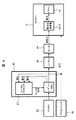
以下、本発明の第1の実施形態について図面を引用しながら説明する。図1は電動パーキングブレーキ装置の全体構成を示している。電動パーキングブレーキ装置は、電動モータ、減速機構、回転/直動変換機構、ピストン、ブレーキパッド及び電子制御手段によって構成されている。 Hereinafter, the first embodiment of the present invention will be described with reference to the drawings. FIG. 1 shows the overall configuration of the electric parking brake device. The electric parking brake device includes an electric motor, a speed reduction mechanism, a rotation / linear motion conversion mechanism, a piston, a brake pad, and electronic control means.
図1及び図2において、電動パーキングブレーキ装置はブレーキ機能を与えるブレーキキャリパ10を備えており、このブレーキキャリパ10を構成するキャリパ本体11の内部には油圧室12が形成されている。油圧室12にはピストン13が配置され、このピストン13は第1ブレーキパッド14を駆動する機能を備えている。また、キャリパ本体11の一端には第2ブレーキパッド15が取り付けられており、第1ブレーキパッド14と第2ブレーキパッド15の間には、車軸に固定されたディスクロータ16が配置されている。このディスクロータ16は第1ブレーキパッド14と第2ブレーキパッド15に挟まれて制動されるものである。
In FIGS. 1 and 2, the electric parking brake device includes a
油圧室12に配置されたピストン13は、油圧系統MBからの油圧によって駆動されるものであり、ブースタ33Aからの液圧配管34Aが接続されており、ブレーキペダル17の操作によってもピストン13に推力が発生する構造である。そして、通常の走行中にブレーキペダル17の操作が行われると、油圧室12に油圧が供給されてピストン13が図2で左側に移動して、第1ブレーキパッド14をディスクロータ16に押し付けて制動動作を行うものである。尚、この油圧による制動動作は駐停車中には作動しないものである。
The
ピストン13は回転/直動変換機構18を介して減速機構19と連結されている。図2にあるように、回転/直動変換機構18は滑りねじを使用したものであり、外周に形成した螺旋状のねじ面を有する回転軸20と、この回転軸20のねじ面に螺合するねじ面を内部に備えた直動部材21より構成されている。直動部材21はピストン13とは切離可能であり、回転軸20の回転によって直動部材21はピストン13を回転軸20の軸方向に移動することができるものである。
The
また、本実施形態では回転/直動変換機構18にはセルフロック機能部が備えられており、回転軸20を回転させれば直動部材21は直動運動するが、回転軸20の回転を停止すれば、直動部材21に直動方向に力が作用しても直動部材21はその位置を保持するものである。すなわち、回転軸20と直動部材21は、摩擦角より進み角が小さい螺旋状のねじ面を有しており、これによってセルフロック機能を得ているものである。この種のねじ面を利用した回転/直動変換機構は良く知られているので、詳細な説明は省略する。
Further, in the present embodiment, the rotation / linear
図1にあるように、回転軸20は減速機構19の大径歯車22に固定されており、大径歯車22は小径歯車23と噛み合っている。小径歯車23は電動モータ24によって回転されるものであり、電動モータ24の回転は小径歯車23、大径歯車22に伝えられて減速されるものである。大径歯車22が回転されることによって、電動モータ24の回転トルクは増幅されて回転軸20に伝えられるものである。
As shown in FIG. 1, the rotating
電動モータ24への電力の供給は、電動モータ制御機能部を備える電子制御手段25によって制御されており、電動モータ制御機能部は周知のマイクロプロセッサや出力回路等からなっている。図1に示す通り電子制御手段25は、バッテリ26の通電/遮断を行うリレー27と、電動モータ24に電圧を印加するためのHブリッジ回路28と、各回路素子(図示せず)を制御するマイクロプロセッサ29と、電動モータ24に流れる電流を検出する電流モニタ回路30と、電動モータ24に印加される上下アーム電圧を検出する上アーム電圧モニタ回路31及び下アーム電圧モニタ回路32と、電源電圧モニタ回路33等から構成されている。
The supply of electric power to the
そして、駐停車する場合は電子制御手段25から電動モータ24に所定の電流を流して電動モータ24を回転し、この回転は減速機構19の各歯車23、22を介して回転軸20を回転させるものである。回転軸20が回転すると直動部材21及びピストン13が左側に移動して第1ブレーキパッド14を所定の推力(押付力)でディスクロータ16に押し付けて制動(パーキングブレーキ)をかけるものである。
Then, when the vehicle is parked or stopped, a predetermined current is passed from the electronic control means 25 to the
そして、電子制御手段25は電動モータ24に所定の電流値(=所定の推力)まで電流を流すと通電を停止するが、電動モータ24への通電が停止されると、回転軸20と直動部材21の間のセルフロック機能部でこの所定の推力を保持して、ディスクロータ16に制動をかけ続けるものである。
Then, the electronic control means 25 stops energization when a current is passed through the
図3は、電動パーキングブレーキ装置を構成するブレーキキャリパ10のピストン13に推力を与える動作時(以下、アプライ動作時と表記する)における推力と電流の挙動を示している。
FIG. 3 shows the behavior of thrust and current during an operation of applying thrust to the
図3において、時刻T1(電圧印加開始時刻)で、作動指令と共に電動モータ24の巻線に電圧が印加されるが、電圧印加直後は電動モータ24が停止状態であるので、このとき誘起電圧は「0」である。その後、電気抵抗とインダクタンスによる時定数に従って、電流が急増する突入電流(IR)が発生する。
In FIG. 3, at time T1 (voltage application start time), a voltage is applied to the winding of the
そして、突入電流(IR)が最大値を迎える直前で電動モータ24の回転が始まるが、電動モータ24の回転により誘起電圧が発生するため、電流は増加から電流(ID)で示すように減少に転じ、暫くすると時刻T2において電流(IC)で示すように電流値がほぼ一定に落ち着く状態となる。この時刻T1〜T2の間は電流減少区間となる。この時刻T2のとき、電動モータ24の回転数もほぼ一定に達する。
Then, the rotation of the
次に、時刻T2からはディスクロータ16をクランプする方向にピストン13が動いていくが、まだブレーキパッド14、15がディスクロータ16を挟み込んでおらずクランプは始まっていない。この時、ピストン13の推力は「0」であり、時刻T2〜T3の間は電流一定区間となる。尚、この「電流一定区間」は、制御上で許容される変動状態をも含むことができものであり、制御上から略一定と見做せる区間を意味している。したがって、以下で「電流一定区間」と表記しているが、制御上から許容される変動状態を含むものである。
Next, from time T2, the
次に、ブレーキパッド14、15がディスクロータ16を挟み込んで電流一定区間が時刻T3で終わると、時刻T3からピストン13に推力が発生する。推力の増加と共に電動モータ24の回転トルク及び電流が増加する。目標推力(F1)で電動モータ24の駆動を停止させるため、マイクロプロセッサ29では目標推力(F1)からカットオフ電流閾値(ISL)を算出し、実際の電動モータ24の巻線に流れる実電流値とカットオフ電流閾値(ISL)とが比較される。
Next, when the
時刻T4で、実電流値がカットオフ電流閾値(ISL)を超え、更に確実に超過したことを確認した後に時刻T5で電圧印加を停止して電流を遮断する。したがって、時刻T4に比べてこの分だけ推力は増加している。そして、この時刻T3〜T5の間はクランプ区間となる。このとき時刻T5では電動モータ24のロータの慣性で回転し続けることを防止するため電動モータ24の端子間を短絡させている。
After confirming that the actual current value exceeds the cutoff current threshold value ( ISL ) at time T4 and is surely exceeded, the voltage application is stopped at time T5 to cut off the current. Therefore, the thrust is increased by this amount as compared with the time T4. Then, the time between T3 and T5 is a clamp section. At this time, at time T5, the terminals of the
クランプ区間が終わり、電動モータ24への電圧が印加されていない状態では、目標推力F1に保持される。これは、逆作動性(逆効率の低い)の回転/直動変換機構18を使用することによって、ピストン13側から押されても電動モータ24が回転しないようにしている。この時刻T5以降は推力保持区間となる。
End clamp section, in the state in which the voltage to the
以上で説明した通り、推力保持区間の保持推力(≒目標推力F1)はカットオフ電流閾値(ISL)によって制御されることが理解できる。ここで、カットオフ電流閾値と保持推力の関係は温度、ハードウェア個体差、電圧などの要因によって変化するが、これらの要因によって保持推力がばらつきを持っても、自動車を停止させるのに必要な最低保持推力は保証されなければならない。 As explained above, it can be understood that the holding thrust (≈target thrust F 1 ) in the thrust holding section is controlled by the cutoff current threshold ( ISL ). Here, the relationship between the cutoff current threshold and the holding thrust changes depending on factors such as temperature, individual hardware differences, and voltage, and even if the holding thrust varies due to these factors, it is necessary to stop the vehicle. The minimum holding thrust must be guaranteed.
そして、保持推力が最低保証推力を下回ると、坂道で駐車した自動車が勝手に動き出す可能性がある。これを防ぐため、想定される多くの条件で保持推力を計算し、保持推力のばらつき分布の中の最小値が最低保証推力を上回るようにカットオフ電流値を決めている。一方、その最大値はメカ効率やモータ特性が良い個体によっては必要以上の推力が発生するため、電動パーキングブレーキ装置の機構系に過度の応力がかかり、耐久性を低下させる要因である。 If the holding thrust falls below the minimum guaranteed thrust, the car parked on the slope may start moving without permission. In order to prevent this, the holding thrust is calculated under many assumed conditions, and the cutoff current value is determined so that the minimum value in the variation distribution of the holding thrust exceeds the minimum guaranteed thrust. On the other hand, the maximum value is a factor that reduces the durability due to excessive stress applied to the mechanical system of the electric parking brake device because an excessive thrust is generated depending on the individual having good mechanical efficiency and motor characteristics.
したがって、最低保証推力を確保しつつ保持推力の上限側への過度のばらつきを抑制することが必要である。言い換えれば、推力を正確に推定することができれば、最低保証推力と許容される上限となる許容上限推力の間に実際の推力を調整することができる。このためには、推力推定モデルの推定パラメータを精度よく求めることが重要である。 Therefore, it is necessary to suppress excessive variation of the holding thrust toward the upper limit while ensuring the minimum guaranteed thrust. In other words, if the thrust can be estimated accurately, the actual thrust can be adjusted between the minimum guaranteed thrust and the permissible upper limit thrust. For this purpose, it is important to accurately obtain the estimation parameters of the thrust estimation model.
また、トルク定数(φ)、粘性係数(η)のいずれのパラメータ推定においても、回転センサで検出した電動モータの回転速度(ω)の情報を演算に用いている。したがって、回転センサを搭載することによる製品単価の上昇を招くという課題も生じるので、この課題に対応することも重要である。 Further, in the estimation of both the torque constant (φ) and the viscosity coefficient (η), the information of the rotation speed (ω) of the electric motor detected by the rotation sensor is used for the calculation. Therefore, there is a problem that the unit price of the product is increased by mounting the rotation sensor, and it is important to deal with this problem.
図4に電動パーキングブレーキ装置の制御モデルのブロックを示している。制御モデルは主にバッテリ26、マスタシリンダ35、マイクロプロセッサ29及び周辺回路を含む電子制御手段25、ハーネス34、電動モータ24、キャリパ10の各コンポーネントから構成されている。これらのコンポーネントの主な接続関係と入出力信号を説明すると、マイクロプロセッサ29は電動モータ24の電流、電圧、及びマスタシリンダ35の液圧の情報に基づいて、電子制御手段25の中のスイッチ(リレー等)にOn/Off指令を出し、バッテリ26の電圧出力をOn/Offする。
FIG. 4 shows a block of a control model of the electric parking brake device. The control model mainly consists of components of a
印加された電圧は、ハーネス34を介して電動モータ24に与えられ、電動モータ24を回転駆動する。電動モータ24で発生した回転トルクは、キャリパ10に入力され、キャリパ10の中では入力された電動モータ24の回転トルクを減速機構19によって増幅し、回転/直動変換機構18を介してピストン13に推力を出力する。また、キャリパ10にはマスタシリンダ35による液圧作用も付与されている。
The applied voltage is applied to the
そして、このような制御モデルに対して、運動方程式、及び回路方程式を導き出すことができる。本実施形態では上述した電動パーキングブレーキ装置の動作を表現する主な要素に基づき、以下に示すような運動方程式、及び回路方程式を導き出した。 Then, the equation of motion and the circuit equation can be derived for such a control model. In this embodiment, the equation of motion and the circuit equation as shown below are derived based on the main elements expressing the operation of the electric parking brake device described above.
まず、図3に示す時刻T3から時刻T5までのクランプ区間の運動方程式を表現すると(1)式及び(2)式のように表される。 First, the equations of motion of the clamp section from the time T3 to the time T5 shown in FIG. 3 are expressed as equations (1) and (2).

![]()
![]()
ここで、(1)式において、「Jdω/dt」は慣性抵抗、「J」は慣性係数、「φ」はトルク定数、「I」は電流、「η」は粘性係数、「ω」は回転速度、「Tfric」は電動モータ24から動力伝達機構の回転/直動変換機構18までを総合した摩擦トルク、「TCLP」は推力のトルク換算値である。尚、粘性係数「η」、トルク定数「φ」、摩擦トルク「Tfric」が、本実施形態で求めようとする推力を推定するための推定パラメータである。
Here, in Eq. (1), "Jdω / dt" is the inertial resistance, "J" is the inertial coefficient, "φ" is the torque constant, "I" is the current, "η" is the viscosity coefficient, and "ω" is the rotation. The speed, "T fric " is the total friction torque from the
また、(1)式中の「KB」は回転/直動変換機構18の回転/直動変換効率に相当し、クランプ区間に回転/直動変換機構で生ずる総摩擦係数等に起因する。尚、本実施形態のアプライ時の動作から、この「KB」は任意の値に設定される。例えば、経験的に得られる値を入力するようにしている。ただ、以下に示すように空走区間では推力に対応する「TCLP」が「0」であるため、空走区間で推定パラメータ(粘性係数、トルク定数、摩擦トルク)を推定する場合には「KB」は無視することができる。
Further, (1) "K B" in the formula corresponds to a rotation / linear motion conversion efficiency of the rotating / linear
また、(2)式において、「FCLP」はピストン13に与えられる推力であり、また、「K」は回転/直動変換係数である。したがって、推力「FCLP」に回転/直動変換係数「K」を乗じてトルク換算値「TCLP」を求めることができる。ここで、回転/直動変換係数「K」は回転/直動変換部の構造から決まるが、ばらつき要因として扱う必要はないものである。
Further, in the equation (2), "F CLP " is the thrust applied to the
ここで、空走区間の運動方程式は、(1)式の推力(トルク換算値)がTCLP=0となるため、(3)式のように表される。 Here, the equation of motion of the free running section is expressed as Eq. (3) because the thrust (torque conversion value) of Eq. (1) is T CLP = 0.
また、電動モータの回路方程式は(4)式のように表される。 The circuit equation of the electric motor is expressed as Eq. (4).
ここで、(4)式において、「V」は電圧、「R」は巻線抵抗、「L」はインダクタンスである。 Here, in the equation (4), "V" is a voltage, "R" is a winding resistance, and "L" is an inductance.
次に、これらの運動方程式と回路方程式に基づくパラメータ推定と推力計算について説明する。上述したように、空走区間の電流、電圧、推力の関係を(3)式及び(4)式で求めた。その際、これらの方程式には未知パラメータが含まれるため、未知パラメータを推定する必要がある。 Next, parameter estimation and thrust calculation based on these equations of motion and circuit equations will be described. As described above, the relationship between the current, voltage, and thrust in the idle section was obtained by Eqs. (3) and (4). At that time, since these equations include unknown parameters, it is necessary to estimate the unknown parameters.
上述した電動パーキングブレーキ装置の(3)式及び(4)式に示す方程式には未知パラメータが含まれている。そして、この中で(4)式の回路方程式について整理すると、回路方程式の右辺は抵抗電圧降下(RI)、インダクタンス電圧降下(LdI/dt)、及び誘起電圧(ωφ)の3項からなり、いずれの項も未知係数、未知変数を含むため、厳密に解くことは難しいが、この3項のうち省略できる要素があるならば、近似的に解くことができる。 Unknown parameters are included in the equations shown in equations (3) and (4) of the electric parking brake device described above. Then, to summarize the circuit equation of Eq. (4) in this, the right side of the circuit equation consists of three terms of resistance voltage drop (RI), inductance voltage drop (LdI / dt), and induced voltage (ωφ). Since the term of does also include unknown coefficients and unknown variables, it is difficult to solve it exactly, but if there is an element that can be omitted from these three terms, it can be solved approximately.
ここで、図5に示す電動モータ24の起動時の過渡的な電流、モータ端子電圧、インダクタンス電圧降下の電気特性に着目すると、インダクタンス電圧降下と誘起電圧が省略できる要素であること判明した。図5にあるように、電動モータ24への通電開始と同時に、インダクタンス電圧はピークを迎えるが、数ms以内に急速に減少して電流値が最大値をとる頃には、インダクタンス電圧は十分小さくなっている。また、電動モータは停止している状態から徐々に回転数を上げるため、起動直後の数ms期間では誘起電圧(モータ端子電圧)が比較的小さいものである。
Here, focusing on the electrical characteristics of the transient current, the motor terminal voltage, and the inductance voltage drop at the time of starting the
これらのことから、電動モータ24の起動時、つまり、アプライ動作の開始時においては、(4)式に示す回路方程式のうち、インダクタンス電圧降下(LdI/dt)と誘起電圧(ωφ)の項を無視できるとするならば、以下の(5)式で示すように電気抵抗(R)が近似して求められる。尚、この電気抵抗(R)は、以下で示す(6)式で使用する誘起電圧(ωφ=V−RI)を求めるのに必要なものである。
From these facts, at the time of starting the
![]()
![]()
そして、この(5)式によって抵抗(R)を求めることができるので、(4)式で誘起電圧(ωφ)が求まる(インダクタンス電圧降下(LdI/dt)は無視できる)。ここで、(3)式に示す (3)式に示す運動方程式にトルク定数(φ)を乗じることで、誘起電圧(ωφ)を用いることができるように運動方程式を(6)式のような変形式とする。これによって、回転センサによる回転情報を使用することが省略できるようになる。尚、この(6)式は離散的に計測した3つの時刻の計測値を用いて表現しているため、行列式の形式となっている。 Then, since the resistance (R) can be obtained by the equation (5), the induced voltage (ωφ) can be obtained by the equation (4) (the inductance voltage drop (LdI / dt) can be ignored). Here, the equation of motion is as shown in Eq. (6) so that the induced voltage (ωφ) can be used by multiplying the equation of motion shown in Eq. (3) by the torque constant (φ). It is a modified equation. This makes it possible to omit the use of rotation information from the rotation sensor. Since this equation (6) is expressed using the measured values of three discretely measured times, it is in the form of a determinant.
次に、(6)式について説明するが、先ず(3)式を用いてトルク定数(φ)、粘性係数(η)、摩擦トルク(Tfric)の推定について説明する。先に求めた空走区間の運動方程式である(3)式は、トルク定数(φ)、粘性係数(η)、摩擦トルク(Tfric)の3個の未知パラメータを含む。このため、3個の未知パラメータを解くためには3個の方程式を立てる必要がある。そして、本実施形態では、電流値が略一定になる電流一定区間に至る前の電流減少区間で3個の方程式を立てるようにしている。 Next, the equation (6) will be described. First, the estimation of the torque constant (φ), the viscosity coefficient (η), and the friction torque (T fric ) will be described using the equation (3). Equation (3), which is the equation of motion of the idle running section obtained above, includes three unknown parameters of torque constant (φ), viscosity coefficient (η), and friction torque (T fric ). Therefore, it is necessary to formulate three equations in order to solve the three unknown parameters. Then, in the present embodiment, three equations are established in the current reduction section before reaching the current constant section in which the current value becomes substantially constant.
つまり、図6に示すように、先ず、電圧印加開始から突入電流が最大値に達するまでの間に、電圧(V)と電流(I)から電気抵抗(R)を推定演算している。これは、(5)式で説明した電動モータ24の起動時に対応するものである。
That is, as shown in FIG. 6, first, the electric resistance (R) is estimated and calculated from the voltage (V) and the current (I) from the start of voltage application to the time when the inrush current reaches the maximum value. This corresponds to the start-up of the
そして、その後の突入電流(IR)が最大値に達した直後から、電流(ID)が減少する電流減少区間内に所定の時間間隔で、例えば、時刻t1でサンプリングSp1、時刻t2でサンプリングSp2、時刻t3でサンプリングSp3を実行して、電圧(V)と電流(I)を計測している。したがって、電流減少区間内で3個の異なる時刻に対する運動方程式を立てることで、運動方程式は3個となり上述した3個の未知パラメータを解くことができる。 Immediately after the subsequent inrush current (IR) reaches the maximum value, sampling Sp1 at time t1 and sampling Sp2 at time t2 are performed at predetermined time intervals within the current reduction section in which the current (ID) decreases. Sampling Sp3 is executed at time t3, and the voltage (V) and the current (I) are measured. Therefore, by formulating the equations of motion for three different times within the current reduction section, the equations of motion become three, and the above-mentioned three unknown parameters can be solved.
ここで、電流値が略一定になる電流一定区間に至る前の電流減少区間で電圧(V)と電流(I)を検出しているため、特許文献1のように電流一定区間が短い場合に粘性係数(η)の推定ができないといった恐れがなくなり、これによって推力の推定が正確にできるようになるものである。
Here, since the voltage (V) and the current (I) are detected in the current decrease section before reaching the current constant section in which the current value becomes substantially constant, when the current constant section is short as in
また、電流減少区間で電圧(V)と電流(I)を測定しているため、夫々の時刻間での測定値の変化量が大きくなり、最終的に推定されるトルク定数(φ)、粘性係数(η)、摩擦トルク(Tfric)の推定精度が高くなるものである。 Further, since the voltage (V) and the current (I) are measured in the current reduction section, the amount of change in the measured value between each time becomes large, and the torque constant (φ) and the viscosity finally estimated are large. The estimation accuracy of the coefficient (η) and the friction torque (T fric ) is improved .
そして、各サンプリングSp1〜Sp3に対して3個の運動方程式を立て、行列形式で表現すると、以下の(6)式で表すことができる。ここで、各サンプリングSp1〜Sp3の時刻での運動方程式を区別するために、サンプリングSp1に対しては時刻「t1」、サンプリングSp2に対しては時刻「t2」、サンプリングSp3に対しては時刻「t3」の符号を付して区別している。また、上述したように(6)式の誘起電圧(ωφ)は、(4)式からインダクタンス電圧降下(LdI/dt)を無視して、ωφ=V−RIの演算を行って求めることができる。 Then, when three equations of motion are set for each sampling Sp1 to Sp3 and expressed in a matrix format, they can be expressed by the following equation (6). Here, in order to distinguish the equations of motion at the times of each sampling Sp1 to Sp3, the time "t1" is for sampling Sp1, the time "t2" is for sampling Sp2, and the time is "t2" for sampling Sp3. The symbols "t3" are added to distinguish them. Further, as described above, the induced voltage (ωφ) in Eq. (6) can be obtained by ignoring the inductance voltage drop (LdI / dt) from Eq. (4) and performing the calculation of ωφ = V-RI. ..
そして、(6)式の右辺の列ベクトル「φ2」、「η」、「Tfricφ」が求める未知の推定パラメータであるため、逆行列を使って、未知の推定パラメータについて解くと(7)式のように表される。 Then, since the column vectors "φ 2 ", "η", and "T fric φ" on the right side of Eq. (6) are unknown estimation parameters, the inverse matrix is used to solve the unknown estimation parameters (7). ) Is expressed as an equation.
ここで、慣性係数「J」はばらつかないと仮定しても良く、既知の値として入力されている。そして、(7)式の右辺に示す誘起電圧(ωφ)と電流(I)から、左辺の未知の推定パラメータであるトルク定数(φ)、粘性係数(η)、摩擦トルク(Tfric)を求めることができる。この場合、左辺の「φ2」の平方根からトルク定数(φ)が求められ、「Tfricφ」をトルク定数(φ)で除することによって摩擦トルク(Tfric)を求めることができる。このように、電圧(V)と電流(I)から(7)式を用いて、空走区間のトルク定数(φ)、粘性係数(η)、摩擦トルク(Tfric)を正確に求めることができるようになる。 Here, it may be assumed that the inertial coefficient “J” does not vary, and is input as a known value. Then, from the induced voltage (ωφ) and current (I) shown on the right side of Eq. (7), the torque constant (φ), viscosity coefficient (η), and friction torque (T fric ), which are unknown estimated parameters on the left side, are obtained. be able to. In this case, the torque constant (φ) can be obtained from the square root of “φ 2 ” on the left side, and the friction torque (T fric ) can be obtained by dividing “T fric φ” by the torque constant (φ). In this way, the torque constant (φ), viscosity coefficient (η), and friction torque (T fric ) of the idle section can be accurately obtained from the voltage (V) and current (I) using the equation (7). become able to.
次に、(1)式と(2)式から推定推力(FCLP)は(8)式で表すことができる。したがって、(7)式からトルク定数(φ)、粘性係数(η)、摩擦トルク(Tfric)が推定されているので、推定推力(FCLP)は以下の(8)式を用いて求めることができる。 Next, the estimated thrust (F CLP ) from Eqs . (1) and (2) can be expressed by Eq. (8). Therefore, since the torque constant (φ), viscosity coefficient (η), and friction torque (T fric ) are estimated from Eq. (7), the estimated thrust (F CLP ) is calculated using Eq. (8) below. Can be done.
ここで、上述した通り、回転/直動変換効率KBは、推定するために必要な方程式が不足しているため推定できないものである。このため、本実施形態では回転/直動変換効率KBは任意の値として入力している。 Here, as described above, the rotation / linear motion conversion efficiency K B are those that can not be estimated due to the lack of equations needed to estimate. Thus, the rotation / linear motion conversion efficiency K B in this embodiment is input as an arbitrary value.
更に、予め定めた目標推力(F* CLP)が与えられる場合、電動モータ24への電流を遮断するときの目標とするカットオフ電流閾値(ISL)は、(8)式を変形して以下の(9)式で求めることができる。この場合は、(7)式から求めたトルク定数(φ)、粘性係数(η)、摩擦トルク(Tfric)を使用すれば良いものである。
Further, when a predetermined target thrust (F * CLP ) is given, the target cutoff current threshold ( ISL ) when interrupting the current to the
更に、必要とされる目標推力を増加方向に変更する場合は、以下の(9)式の目標推力(F* CLP)を変更することでカットオフ電流閾値(ISL)は高く再設定され、逆に目標推力(F* CLP)が過剰であれば、カットオフ電流閾値(ISL)を低く再設定してやれば良いものである。この場合、カットオフ電流閾値(ISL)は、演算周期に合わせて所定値だけ段階的に補正(増加或いは減少)することが可能である。 Furthermore, when changing the required target thrust in the increasing direction, the cutoff current threshold ( ISL ) is reset to a higher value by changing the target thrust (F * CLP ) in Eq. (9) below. On the contrary, if the target thrust (F * CLP ) is excessive, the cutoff current threshold ( ISL ) may be reset to a low value. In this case, the cutoff current threshold value ( ISL ) can be gradually corrected (increased or decreased) by a predetermined value according to the calculation cycle.
更に、演算式を用いて変換することに代えて、推力と電流値を対応付けたテーブルを予め作成しておき、推力が補正された時点でテーブル検索を実行してカットオフ電流閾値(ISL)を求めるようにしても良い。この方法によれば、演算時間を短縮できる効果が期待できる。
このように、トルク定数(φ)、粘性係数(η)、摩擦トルク(Tfric)を反映することで目標カットオフ電流閾値(ISL)が求まるので、正確な推力に管理することができる。
Further, instead of converting using an arithmetic expression, a table in which the thrust and the current value are associated is created in advance, and when the thrust is corrected, the table search is executed to perform the cutoff current threshold ( ISL). ) May be obtained. According to this method, the effect of shortening the calculation time can be expected.
Thus, the torque constant (phi), viscosity coefficient (eta), since the target cutoff current threshold (I SL) is obtained by reflecting the friction torque (T Fric), can be managed in the correct thrust.
以上のように、(7)式に示すパラメータ推定式、(8)式に示す推力計算式、及び(9)式に示す電流閾値式を導き出したが、次に(7)式のパラメータ推定式と(8)式の推力計算式を用いて推力制御をする場合の処理の流れを、図7の制御ブロックによって説明する。 As described above, the parameter estimation formula shown in Eq. (7), the thrust calculation formula shown in Eq. (8), and the current threshold formula shown in Eq. (9) were derived. Next, the parameter estimation formula in Eq. (7) was derived. The flow of processing in the case of thrust control using the thrust calculation formula of Eq. (8) will be described with reference to the control block of FIG.
図7において、検出する測定パラメータは電圧(V)と電流(I)だけである。これによって、回転センサを省略して製品単価の上昇を抑制することができる。また、回転センサの出力誤差の修正が必要なくなり、更に、回転センサの故障に対するフェールセーフ機能を搭載する必要がなくなる、という効果を奏することができる。 In FIG. 7, the only measurement parameters to be detected are voltage (V) and current (I). As a result, the rotation sensor can be omitted and the increase in the product unit price can be suppressed. Further, it is not necessary to correct the output error of the rotation sensor, and further, it is not necessary to install a fail-safe function against the failure of the rotation sensor.
また、この電圧(V)と電流(I)の検出時刻は図6に示している通りである。このため、電流値が略一定になる電流一定区間に至る前の電流減少区間で電圧(V)と電流(I)を検出することで、特許文献1のように電流一定区間で粘性係数等のような推定パラメータの推定を行なわないので、推力の推定が正確にできるようになる。更に、電流減少区間で電圧(V)と電流(I)を測定しているため、夫々の時刻間での測定値の変化量が大きくなり、最終的に推定されるトルク定数(φ)、粘性係数(η)、摩擦トルク(Tfric)の推定精度が高くなるものである。
The detection times of the voltage (V) and the current (I) are as shown in FIG. Therefore, by detecting the voltage (V) and the current (I) in the current decrease section before reaching the current constant section in which the current value becomes substantially constant, the viscosity coefficient or the like can be obtained in the current constant section as in
図7において、抵抗/誘起電圧推定部40には電圧(V)と電流(I)が入力され、電動モータ24の起動時に、(5)式を用いて電圧(V)と電流(I)から電気抵抗(R)を求めている。また、抵抗/誘起電圧推定部40は、この求められた電気抵抗(R)の最小値を選択し、誘起電圧推定部41では、(4)式を用いて電圧(V)、電流(I)及び電気抵抗(R)から、誘起電圧(ωφ=V−RI)を演算して求めている。
In FIG. 7, the voltage (V) and the current (I) are input to the resistance / induced voltage estimation unit 40, and when the
この誘起電圧(ωφ)と電流(I)は、次の機械パラメータ推定部42に入力される。ここで、抵抗/誘起電圧推定部40は、温度補償機能を備えており、この温度補償機能は、電動モータ24の電圧(V)、電流(I)及び電気抵抗(R)に基づいて誘起電圧(ωφ=V−RI)を推定しているので、電動モータ24の温度による推力変化を補償することができる。
The induced voltage (ωφ) and current (I) are input to the next machine
機械パラメータ推定部42ではトルク定数(φ)、粘性係数(η)、摩擦トルク(Tfric)を推定している。機械パラメータ推定部42には、誘起電圧(ωφ)と電流(I)が入力されており、誘起電圧(ωφ)は微分されて微分値(dωφ/dt)となり、パラメータ推定部43に入力される。更に、パラメータ推定部43には、微分される前の誘起電圧(ωφ)と電流(I)が入力されている。これらの入力は、(7)式にあるパラメータ推定式を用いてトルク定数(φ)、粘性係数(η)、摩擦トルク(Tfric)を推定するために使用されている。
The mechanical
機械パラメータ推定部42において、(7)式を用いて推定されたトルク定数(φ)、粘性係数(η)、及び摩擦トルク(Tfric)は、次の目標カットオフ電流閾値演算部46に入力される。
The torque constant (φ), viscosity coefficient (η), and friction torque (T fric ) estimated by the machine
目標カットオフ電流閾値演算部46は(9)式に基づいて目標とするカットオフ電流閾値(ISL)を求める。カットオフ電流閾値(ISL)は比較器47に入力されて実電流値と比較され、実電流値がカットオフ電流閾値(ISL)を超えるとカットオフ信号を出力する。このようにして、電子制御手段25は、実際に電動モータ24に流れている実電流値がカットオフ電流閾値(ISL)に達すると、電動モータ24に供給されている電流を遮断して推力保持区間に移行することになる。
The target cutoff current threshold
以上述べた通り、本発明によれば、ピストンの推力を制御するカットオフ電流閾値演算モデルを備えると共に、電動モータに通電を開始した時に生じる突入電流の後の電流が略一定になる電流一定区間に至る前の電流減少区間内で、少なくとも電動モータに印加される電圧値と電流値を複数回に亘って計測し、この複数の電圧値と電流値を用いて所定の推定演算を行ってカットオフ電流閾値演算部に使用される推定パラメータを推定し、この推定パラメータを用いてカットオフ電流閾値の演算を行なう構成とした。 As described above, according to the present invention, a cutoff current threshold calculation model for controlling the thrust of the piston is provided, and a constant current section in which the current after the inrush current generated when the electric motor is energized becomes substantially constant. Within the current reduction section before reaching, at least the voltage value and current value applied to the electric motor are measured multiple times, and a predetermined estimation calculation is performed using these multiple voltage values and current values to cut. The estimation parameter used in the off-current threshold calculation unit is estimated, and the cut-off current threshold is calculated using this estimation parameter.
これによれば、電流一定区間に至る前の電流減少区間内に、カットオフ電流閾値演算部の推定パラメータを確実に推定演算することができ、カットオフ電流閾値演算部による正確なカットオフ電流閾値の推定を行なうことができる。また、これらの推定パラメータの推定に回転センサによる回転速度情報を使用しないので、回転センサを省略することができる。 According to this, the estimation parameter of the cutoff current threshold calculation unit can be reliably estimated and calculated within the current reduction section before reaching the current constant section, and the cutoff current threshold calculation unit accurately calculates the cutoff current threshold. Can be estimated. Further, since the rotation speed information by the rotation sensor is not used for estimating these estimation parameters, the rotation sensor can be omitted.
次に本発明の第2の実施形態について説明するが、ここで、図1〜図6までは実施例1と同様なので説明を省略する。そして、実施例1と同様に、電動パーキングブレーキ装置の動作を表現する主な構成要素の運動方程式、及び回路方程式を導き出すことができる。 Next, a second embodiment of the present invention will be described. Here, since FIGS. 1 to 6 are the same as those of the first embodiment, the description thereof will be omitted. Then, as in the first embodiment, the equations of motion and the circuit equations of the main components expressing the operation of the electric parking brake device can be derived.
図3に示す時刻T1から時刻T3までの空走区間の運動方程式を表現すると以下の(10)式のように表される。 The equation of motion of the idle section from time T1 to time T3 shown in FIG. 3 is expressed by the following equation (10).
ここで、(10)式における空走区間の運動方程式は、実施例1で説明した(3)式のうち、粘性係数「η」、摩擦トルク「Tfric」に関する成分をひとまとめにして、空走期間合成摩擦トルク「TLoss」によって表し直している。 Here, the equation of motion of the idle running section in the equation (10) is a combination of the components related to the viscosity coefficient “η” and the friction torque “T fric ” in the equation (3) described in the first embodiment, and the idle running. It is re-expressed by the period combined friction torque "T Ross ".
次に、これらの運動方程式と回路方程式に基づくパラメータ推定と推力計算について説明する。上述したように、空走区間の電流、電圧、推力の関係を(10)式及び(4)式で求めた。その際、これらの方程式には未知パラメータが含まれるため、未知パラメータを推定する必要がある。 Next, parameter estimation and thrust calculation based on these equations of motion and circuit equations will be described. As described above, the relationship between the current, voltage, and thrust in the idle section was obtained by Eqs. (10) and (4). At that time, since these equations include unknown parameters, it is necessary to estimate the unknown parameters.
上述した電動パーキングブレーキ装置の(10)式及び(4)式に示す方程式には未知パラメータが含まれている。そして、この中で(4)式の回路方程式について整理すると、回路方程式の右辺は抵抗電圧降下(RI)、インダクタンス電圧降下(LdI/dt)、及び誘起電圧(ωφ)の3項からなり、いずれの項も未知係数、未知変数を含むため、厳密に解くことは難しいが、この3項のうち省略できる要素があるならば、近似的に解くことができる。 The equations shown in equations (10) and (4) of the electric parking brake device described above include unknown parameters. Then, to summarize the circuit equation of Eq. (4) in this, the right side of the circuit equation consists of three terms of resistance voltage drop (RI), inductance voltage drop (LdI / dt), and induced voltage (ωφ). Since the term of does also include unknown coefficients and unknown variables, it is difficult to solve it exactly, but if there is an element that can be omitted from these three terms, it can be solved approximately.
電動モータ24の起動時、つまり、アプライ動作の開始時においては、(4)式に示す回路方程式のうち、インダクタンス電圧降下(LdI/dt)を無視できるとするならば、以下の(11)式で示すように電気抵抗(R)が近似して求められる。(5)式と異なり、除算する電流値を「Imax+ΔIavr×N」とすることによって、誘起電圧(ωφ)の影響を最小限に抑えることが可能である。
If the inductance voltage drop (LdI / dt) can be ignored in the circuit equation shown in Eq. (4) at the start of the
ここで電流値(Imax)は、突入電流(IR)のピーク値付近の電流値であり、電流変化値(ΔIavr)は、電流のピーク値以降の電流(ID)の変化を移動平均した電流変化値、回数(N)はアプライ開始から電流ピーク値までのサンプル回数であり、これを図8によって説明する。尚、機械時定数(慣性係数「J」や摩擦等から見積もられ、式中には表示せず)に対して十分短い時間では、回転速度(ω)は線形に減少すると仮定できる(回転速度変化の線形近似)。 Here, the current value (I max ) is a current value near the peak value of the inrush current (IR), and the current change value (ΔI avr ) is a moving average of changes in the current (ID) after the peak value of the current. The current change value and the number of times (N) are the number of samples from the start of application to the current peak value, which will be described with reference to FIG. It can be assumed that the rotation speed (ω) decreases linearly in a time sufficiently short with respect to the machine time constant (estimated from the inertial coefficient "J", friction, etc., and is not displayed in the equation). Linear approximation of change).
したがって、回転速度(ω)に比例する誘起電圧(ωφ)も線形に減少する。ここで、インダクタンス電圧降下(LdI/dt)の影響が小さくなるのは電流のピーク値以降であることから、電流のピーク値以降の電流変化は誘起電圧(ωφ)の線形変化によるものである。図8に示すように電流のピーク値以降の値から電流変化値(ΔIavr)を算出し、アプライ開始時点の電流値を外挿することで誘起電圧の影響を補正できる。 Therefore, the induced voltage (ωφ), which is proportional to the rotation speed (ω), also decreases linearly. Here, since the influence of the inductance voltage drop (LdI / dt) becomes small after the peak value of the current, the current change after the peak value of the current is due to the linear change of the induced voltage (ωφ). As shown in FIG. 8, the influence of the induced voltage can be corrected by calculating the current change value (ΔI avr ) from the value after the peak value of the current and extrapolating the current value at the start of application.
本実施形態では、電流値が略一定になる電流一定区間に至る前の電流減少区間で、以下の(11)式を計算するようにしている。 In the present embodiment, the following equation (11) is calculated in the current reduction section before reaching the current constant section in which the current value becomes substantially constant.
![]()
![]()
つまり、図9、及び図8に示すように、先ず、ステップS10で、電圧印加開始から突入電流が最大値に達するまでの間のタイミングをカウントする。 That is, as shown in FIGS. 9 and 8, first, in step S10, the timing from the start of voltage application until the inrush current reaches the maximum value is counted.
続いて、ステップS11、S12、S13、S14に進んで、電流減少区間で電流(ID)の時間変化分の移動平均値(ΔIavr)から「ΔIavr×N」を計算し、突入電流のピーク値付近の電流値(Imax)と「ΔIavr×N」、およびモニタしている電圧(V:電源印加直後が望ましい)から、(11)式のように電気抵抗(R)を推定演算している。これは、電動モータ24の起動時に対応するものである。
Subsequently, the process proceeds to steps S11, S12, S13, and S14, and "ΔI avr × N" is calculated from the moving average value (ΔI avr ) of the time change of the current (ID) in the current decrease section, and the peak of the inrush current is calculated. From the current value (I max ) near the value, "ΔI avr × N", and the monitored voltage (V: preferably immediately after applying the power supply), the electrical resistance (R) is estimated and calculated as in Eq. (11). ing. This corresponds to the start-up of the
そして、ステップS14で(11)式の演算結果を算出した後、ステップS15で電気抵抗(R)を上下限値でリミット処理し、電気抵抗(R)の推定処理が完了する。 Then, after calculating the calculation result of the equation (11) in step S14, the electric resistance (R) is limited by the upper and lower limit values in step S15, and the estimation process of the electric resistance (R) is completed.
本実施形態では、突入電流のピーク値付近の電流値を用いているので、モータ電流のピーク電流を必ずしもサンプリングできなくても、電気抵抗(R)の推定精度を向上できる利点がある。 In the present embodiment, since the current value near the peak value of the inrush current is used, there is an advantage that the estimation accuracy of the electric resistance (R) can be improved even if the peak current of the motor current cannot always be sampled.
そして、この(11)式によって電気抵抗(R)を求めることができるので、(4)式で誘起電圧(ωφ)が求まる。ここで、(10)式に示す運動方程式にトルク定数(φ)を乗じることで、誘起電圧(ωφ)を用いることができるように運動方程式を以下の(12)式のような変形式とする。尚、時刻t1と時刻t2の時間間隔が空走期間合成摩擦トルク(TLoss)の変化に対して十分小さいとして、空走期間合成摩擦トルク(TLoss)を一定値と見做すことができる。 Then, since the electric resistance (R) can be obtained by the equation (11), the induced voltage (ωφ) can be obtained by the equation (4). Here, by multiplying the equation of motion shown in equation (10) by the torque constant (φ), the equation of motion is modified as in equation (12) below so that the induced voltage (ωφ) can be used. .. Incidentally, as the time interval between time t1 and time t2 is sufficiently small relative to the change in the air-run period synthetic friction torque (T Loss), it can be regarded as a constant value an empty run time synthetic friction torque (T Loss) ..
(12)式から(TLossφ)を消去すると、以下の(13)式になる。 Eliminating (T Loss φ) from equation (12) yields equation (13) below.
更に,(13)式を(φ)について解くと、以下の(14)式となる。 Further, when equation (13) is solved for (φ), the following equation (14) is obtained.
本実施形態では、電流値が略一定になる電流一定区間に至る前の電流減少区間で(14)式を計算するようにしている。つまり、図11、及び図10に示すように、ステップS20で、電流(ID)が減少する電流減少区間内に所定の時間間隔で、例えば、時刻t1でサンプリングSp1、時刻t2でサンプリングSp2を実行して、電圧(V)と電流(I)を計測している。そして、ステップS21〜22に進んで電流減少区間内で少なくとも2個の異なる時刻に対する運動方程式を立てることで、(12)式の2個の未知パラメータ(φ2)(TLossφ)の内、(TLossφ)消去して、トルク定数(φ)を解くことができる。 In the present embodiment, the equation (14) is calculated in the current decrease section before reaching the current constant section in which the current value becomes substantially constant. That is, as shown in FIGS. 11 and 10, in step S20, sampling Sp1 is executed at time t1 and sampling Sp2 is executed at time t2 at predetermined time intervals within the current reduction section in which the current (ID) decreases. Then, the voltage (V) and the current (I) are measured. Then, by proceeding to steps S21 to 22 and formulating equations of motion for at least two different times in the current reduction section, among the two unknown parameters (φ 2 ) (T Loss φ) of Eq. (12), (T Loss φ) can be erased to solve the torque constant (φ).
また、電流減少区間で電圧(V)と電流(I)を測定しているため、夫々の時刻間での測定値の変化量が大きくなり、最終的に推定されるトルク定数(φ)の推定精度が高くなるものである。 In addition, since the voltage (V) and the current (I) are measured in the current reduction section, the amount of change in the measured value between each time becomes large, and the final estimated torque constant (φ) is estimated. The accuracy is high.
また、上述したように(12)式〜(14)式の誘起電圧(ωφ)は、(4)式のインダクタンス電圧降下(LdI/dt)を無視して、「ωφ=V−RI」の演算を行って求めることができる。 Further, as described above, the induced voltage (ωφ) in Eqs. (12) to (14) is calculated as “ωφ = V-RI” by ignoring the inductance voltage drop (LdI / dt) in Eq. (4). Can be obtained by doing.
そして、(14)式の演算結果を算出した後、ステップS23〜S25に進んで、トルク定数(φ)の上下限値でリミット処理し、現在とn0サンプル前のとトルク定数(φ)の差が設定値以下に入ったらトルク定数(φ)の推定が完了する。 Then, after calculating the calculation result of Eq. (14), the process proceeds to steps S23 to S25, limit processing is performed with the upper and lower limit values of the torque constant (φ), and the difference between the current value and the torque constant (φ) before the n0 sample. When is less than the set value, the estimation of the torque constant (φ) is completed.
そして、最後に(TLossφ)を求める。(4)式より求めた誘起電圧(ωφ)と、(10)式にφを乗じた式から、「TLossφ」が求まり、更にトルク定数(φ)で除算すれば、空走期間合成摩擦トルク「TLoss」が求まる。 Finally, (T Loss φ) is obtained. The "T Ross φ" can be obtained from the induced voltage (ωφ) obtained from the equation (4) and the equation obtained by multiplying the equation (10) by φ, and further divided by the torque constant (φ), the combined friction during the idle running period The torque "T Ross " is obtained.
この空走期間合成摩擦トルク「TLoss」の推定動作を図12、図13に示している。ステップS30、S31において、空走期間合成摩擦トルク「TLoss」推定を開始するのは電流減少区間(ID)である。推定を始め、徐々に「TLoss」が真値に近しい値に収束し、空走期間合成摩擦トルク「TLoss」演算値の変化が緩やかになったところで、空走期間合成摩擦トルク「TLoss」推定が完了する。そして、ステップS32〜S34に進んで、空走期間合成摩擦トルク「TLoss」の演算結果を(TLoss)の上下限値でリミット処理し、現在とn0サンプル前の空走期間合成摩擦トルク「TLoss」の演算値の差が設定値以下に入ったら、空走期間合成摩擦トルク「TLoss」の推定が完了する。 The estimation operation of the combined friction torque "T Ross " during the idle running period is shown in FIGS. 12 and 13. In steps S30 and S31, it is the current reduction section (ID) that starts the estimation of the combined friction torque "T Loss " during the idle running period. When the estimation is started, "T Loss " gradually converges to a value close to the true value, and the change in the calculated value of the combined friction torque "T Loss " during the idle running period becomes gradual, the combined friction torque "T Loss " during the free running period becomes gentle. The estimation is completed. Then, in steps S32 to S34, the calculation result of the idle running period combined friction torque "T Loss " is limited by the upper and lower limit values of (T Loss ), and the idle running period combined friction torque "currently and n0 samples before" is limited. When the difference between the calculated values of "T Ross " is less than or equal to the set value, the estimation of the combined friction torque "T Loss " during the idle running period is completed.
空走期間合成摩擦トルク「TLoss」の推定においても、電流減少区間で推定することにより、推定値の収束状態から推定精度を管理することが可能になる。また、空走区間の中の推定できる安定な状態が短時間となる場合にも確実に推定でき、高信頼化できる利点がある。 Even in the estimation of the combined friction torque "T Loss " during the idle running period, it is possible to manage the estimation accuracy from the converged state of the estimated values by estimating in the current reduction section. In addition, there is an advantage that it can be reliably estimated even when the stable state that can be estimated in the idle section is short, and high reliability can be achieved.
このように、トルク定数(φ)、空走期間合成摩擦トルク(TLoss)を以下の(15)式に反映することで、目標カットオフ電流閾値(ISL)が求まるので、正確な推力に管理することができる。 In this way, by reflecting the torque constant (φ) and the combined friction torque ( TL Ross ) during the idle running period in the following equation (15), the target cutoff current threshold ( ISL ) can be obtained, so that the thrust can be accurate. Can be managed.
尚、カットオフ電流閾値(ISL)を実電流値と比較しカットオフ信号を出力する処理は実施例1と同じであるため説明は省略する。 Since the process of comparing the cutoff current threshold value ( ISL ) with the actual current value and outputting the cutoff signal is the same as that of the first embodiment, the description thereof will be omitted.
このようにして、電子制御手段25は、実際に電動モータ24に流れている実電流値がカットオフ電流閾値(ISL)に達すると、電動モータ24に供給されている電流を遮断して推力保持区間に移行することになる。
In this way, when the actual current value actually flowing through the
以上述べた通り、本発明によれば、ピストンの推力を制御するカットオフ電流閾値演算部を備えると共に、電動機に通電を開始した時に生じる突入電流の後の電流が略一定になる電流一定区間に至る前の電流減少区間内で、少なくとも電動機に印加される電圧値と電流値を複数回に亘って計測し、この複数の電圧値と電流値を用いて所定の演算を行って推力推定モデルに使用される推定パラメータを推定し、これらの推定パラメータを用いてカットオフ電流閾値演算部によるカットオフ電流閾値の演算を行なう構成とした。ところにある。 As described above, according to the present invention, the cutoff current threshold value calculation unit for controlling the thrust of the piston is provided, and the current constant section in which the current after the inrush current generated when the electric motor is started to be energized becomes substantially constant is provided. Within the current reduction section before reaching, at least the voltage value and current value applied to the motor are measured multiple times, and a predetermined calculation is performed using these multiple voltage values and current values to create a thrust estimation model. The estimation parameters to be used are estimated, and the cutoff current threshold is calculated by the cutoff current threshold calculation unit using these estimation parameters. There is.
これによれば、電流一定区間に至る前の電流減少区間内に、推力推定モデルの推定パラメータを精度よく推定演算することができ、推力推定モデルによる正確な推力の推定を行なうことができる。 According to this, the estimation parameters of the thrust estimation model can be accurately estimated and calculated in the current reduction section before reaching the current constant section, and the thrust can be estimated accurately by the thrust estimation model.
尚、本発明は上記した実施形態に限定されるものではなく、様々な変形例が含まれる。例えば、上記した実施形態は本発明を分かりやすく説明するために詳細に説明したものであり、必ずしも説明した全ての構成を備えるものに限定されるものではない。また、ある実施形態の構成の一部を他の実施形態の構成に置き換えることが可能であり、また、ある実施形態の構成に他の実施形態の構成を加えることも可能である。また、各実施形態の構成の一部について、他の構成の追加・削除・置換をすることが可能である。 The present invention is not limited to the above-described embodiment, and includes various modifications. For example, the above-described embodiment has been described in detail in order to explain the present invention in an easy-to-understand manner, and is not necessarily limited to the one including all the described configurations. Further, it is possible to replace a part of the configuration of one embodiment with the configuration of another embodiment, and it is also possible to add the configuration of another embodiment to the configuration of one embodiment. Further, it is possible to add / delete / replace a part of the configuration of each embodiment with another configuration.
10…ブレーキキャリパ、11…キャリパ本体、12…油圧室、13…ピストン、14,15…ブレーキパッド、16…ディスクロータ、17…ブレーキペダル、18…回転/直動変換機構、19…減速機構、20…回転軸、21…直動部材、22…大径歯車、23…小径歯車、24…電動モータ、25…電子制御手段、26…バッテリ、27…リレー、28…Hブリッジ回路、29…マイクロプロセッサ、30…電流モニタ回路、31…上アーム電圧モニタ回路、32…下アーム電圧モニタ回路、33…電源電圧モニタ回路、34…ハーネス、35…マスタシリンダ、40…抵抗/誘起電圧推定部、41…誘起電圧推定部、42…機械パラメータ推定部、43…パラメータ推定部、46…目標カットオフ電流閾値演算部、47…比較器。 10 ... Brake caliper, 11 ... Caliper body, 12 ... Hydraulic chamber, 13 ... Piston, 14, 15 ... Brake pad, 16 ... Disc rotor, 17 ... Brake pedal, 18 ... Rotation / linear motion conversion mechanism, 19 ... Deceleration mechanism, 20 ... Rotating shaft, 21 ... Linear member, 22 ... Large diameter gear, 23 ... Small diameter gear, 24 ... Electric motor, 25 ... Electronic control means, 26 ... Battery, 27 ... Relay, 28 ... H bridge circuit, 29 ... Micro Processor, 30 ... Current monitor circuit, 31 ... Upper arm voltage monitor circuit, 32 ... Lower arm voltage monitor circuit, 33 ... Power supply voltage monitor circuit, 34 ... Harness, 35 ... Master cylinder, 40 ... Resistance / induced voltage estimation unit, 41 ... Induced voltage estimation unit, 42 ... Mechanical parameter estimation unit, 43 ... Parameter estimation unit, 46 ... Target cutoff current threshold calculation unit, 47 ... Comparer.
Claims (6)
前記電子制御手段は、
前記ピストンの推力を制御するカットオフ電流閾値演算部を備えると共に、
前記電動機に通電を開始した時に生じる突入電流の後の電流が略一定になる電流一定区間に至る前の電流減少区間内で、少なくとも前記電動機に印加される電圧値と電流値を複数回に亘って計測し、この複数の前記電圧値と前記電流値を用いて所定の演算を行って推力推定モデルに使用される推定パラメータを推定し、これらの推定パラメータを用いて前記カットオフ電流閾値演算部によるカットオフ電流閾値の演算を行なうと共に、
前記カットオフ電流閾値演算部は、トルク定数、粘性係数、及び摩擦トルクを用いて前記カットオフ電流閾値を求める演算部であり、
更に、前記カットオフ電流閾値演算部は、
前記電動機に電流が流れ始めて前記突入電流が最大値に達する区間及び前記突入電流の後の電流が略一定になる電流一定区間に至る前の前記電流減少区間内のいずれかで、前記電圧値と前記電流値から電気抵抗値を求める電気抵抗推定機能と、
前記突入電流が最大値に達した後の前記電流減少区間内で、夫々の計測回毎に前記電気抵抗値と前記電流値と前記電圧値から誘起電圧値を求める誘起電圧推定機能と、
前記夫々の計測回毎の前記誘起電圧値と前記電流値を用いて前記所定の演算を行うことで、前記トルク定数、前記粘性係数、及び前記摩擦トルクを推定するパラメータ推定機能と、
前記トルク定数、前記粘性係数、及び前記摩擦トルクを前記推力推定モデルに入力して推力を求める推力推定機能とを備える
ことを特徴とする電動パーキングブレーキ装置。 A piston that presses the brake pad against the disc rotor, a rotation / linear motion conversion mechanism that converts the rotary motion output by the electric motor into linear motion and propels the piston, and a rotary / linear motion conversion mechanism that is provided in the rotary / linear motion conversion mechanism and operates in reverse. In an electric parking brake device provided with a self-locking function unit for suppressing the rotation of the electric motor and an electronic control means for controlling the rotation of the electric motor.
The electronic control means
In addition to being provided with a cutoff current threshold value calculation unit that controls the thrust of the piston,
Within the current reduction section before reaching the current constant section where the current after the inrush current that occurs when the electric motor is energized becomes substantially constant, at least the voltage value and the current value applied to the motor are applied a plurality of times. The cutoff current threshold value calculation unit uses these estimated parameters to estimate the estimated parameters used in the thrust estimation model by performing predetermined calculations using the plurality of the voltage values and the current values. with performing the calculation of the cut-off current threshold by,
The cutoff current threshold calculation unit is a calculation unit that obtains the cutoff current threshold using the torque constant, the viscosity coefficient, and the friction torque.
Further, the cutoff current threshold calculation unit is
With the voltage value, either in the section where the current starts to flow in the motor and the inrush current reaches the maximum value, or in the current reduction section before reaching the current constant section where the current after the inrush current becomes substantially constant. The electric resistance estimation function that obtains the electric resistance value from the current value, and
Within the current decrease section after the inrush current reaches the maximum value, an induced voltage estimation function for obtaining an induced voltage value from the electric resistance value, the current value, and the voltage value at each measurement time,
A parameter estimation function for estimating the torque constant, the viscosity coefficient, and the friction torque by performing the predetermined calculation using the induced voltage value and the current value for each measurement time.
An electric parking brake device including a thrust estimation function for inputting the torque constant, the viscosity coefficient, and the friction torque into the thrust estimation model to obtain a thrust .
前記電子制御手段は、
前記電動機に流れる電流の実電流値が前記カットオフ電流閾値に達すると前記電動機に流れる電流を遮断する電流遮断機能部を備える
ことを特徴とする電動パーキングブレーキ装置。 In the electric parking brake device according to claim 1,
The electronic control means
An electric parking brake device including a current cutoff function unit that cuts off the current flowing through the electric motor when the actual current value of the current flowing through the electric motor reaches the cutoff current threshold value.
前記パラメータ推定機能は、
前記電流減少区間における、前記電動機から前記回転/直動変換機構までの運動方程式に前記トルク定数を乗じた変形式を求め、この変形式に前記夫々の計測回毎の前記電流値と前記誘起電圧値を代入して前記トルク定数、前記粘性係数、及び前記摩擦トルクを含む未知パラメータを推定演算して前記トルク定数、前記粘性係数、及び前記摩擦トルクを求める
ことを特徴とする電動パーキングブレーキ装置。 In the electric parking brake device according to claim 1,
The parameter estimation function
In the current reduction section, a deformation formula obtained by multiplying the equation of motion from the electric motor to the rotation / linear motion conversion mechanism by the torque constant is obtained, and the current value and the induced voltage for each measurement time are obtained in this deformation formula. An electric motor characterized in that the torque constant, the viscosity coefficient, and the friction torque are obtained by estimating and calculating an unknown parameter including the torque constant, the viscosity coefficient, and the friction torque by substituting the values. Parking brake device.
前記電動機の通電後、カットオフ電流閾値まで前記電動機を駆動する制御装置と、
前記電動機を前記カットオフ電流閾値まで駆動したときに、前記制動部材を前記被制動部材に押圧した状態で車両の制動を保持する制動機構と、を有し、
前記制御装置は、前記電動機への通電開始時の突入電流が減少する期間における前記電動機の電圧値と前記電動機の電流値とに応じて前記カットオフ電流閾値を変更し、この変更した前記カットオフ電流閾値まで前記電動機を駆動するブレーキ装置において、
前記制御装置は、
前記カットオフ電流閾値を演算するカットオフ電流閾値演算部を備え、
前記電動機に通電を開始した時に生じる突入電流の後の電流が略一定になる電流一定区間に至る前の電流減少区間内で、少なくとも前記電動機に印加される前記電圧値と前記電流値を複数回に亘って計測し、この複数の前記電圧値と前記電流値を用いて所定の演算を行って推力推定モデルに使用される推定パラメータを推定し、これらの推定パラメータを用いて前記カットオフ電流閾値演算部による前記カットオフ電流閾値の演算を行なうと共に、
前記カットオフ電流閾値演算部は、トルク定数、粘性係数、及び摩擦トルクを用いて前記カットオフ電流閾値を求める演算部であり、
更に、前記カットオフ電流閾値演算部は、
前記電動機に電流が流れ始めて前記突入電流が最大値に達する区間及び前記突入電流の後の電流が略一定になる電流一定区間に至る前の電流減少区間内のいずれかで、前記電圧値と前記電流値から電気抵抗値を求める電気抵抗推定機能と、
前記突入電流が最大値に達した後の前記電流減少区間内で、夫々の計測回毎に前記電気抵抗値と前記電流値と前記電圧値から誘起電圧値を求める誘起電圧推定機能と、
前記夫々の計測回毎の前記誘起電圧値と前記電流値を用いて前記所定の演算を行うことで、前記トルク定数、前記粘性係数、及び前記摩擦トルクを推定するパラメータ推定機能と、
前記トルク定数、前記粘性係数、及び前記摩擦トルクを前記推力推定モデルに入力して推力を求める推力推定機能とを備える
ことを特徴とするブレーキ装置。 An electric motor that powers the braking member to press it against the braked member,
After the electric motor is energized, the control device that drives the electric motor to the cutoff current threshold and
It has a braking mechanism that holds the braking of the vehicle while the braking member is pressed against the braked member when the electric motor is driven to the cutoff current threshold value.
The control device changes the cutoff current threshold value according to the voltage value of the motor and the current value of the motor during the period in which the inrush current at the start of energization of the motor decreases, and the changed cutoff In the braking device that drives the electric motor to the current threshold,
The control device is
A cutoff current threshold value calculation unit for calculating the cutoff current threshold value is provided.
Within the current reduction section before reaching the current constant section in which the current after the inrush current generated when the electric motor is energized becomes substantially constant, the voltage value applied to the motor and the current value are applied a plurality of times. The estimation parameters used in the thrust estimation model are estimated by performing a predetermined calculation using the plurality of the voltage values and the current values, and the cutoff current threshold value is used using these estimation parameters. The calculation unit calculates the cutoff current threshold and also
The cutoff current threshold calculation unit is a calculation unit that obtains the cutoff current threshold using the torque constant, the viscosity coefficient, and the friction torque.
Further, the cutoff current threshold calculation unit is
The voltage value and the said voltage value in either the section where the current starts to flow in the motor and the inrush current reaches the maximum value or the current decrease section before reaching the current constant section where the current after the inrush current becomes substantially constant. The electric resistance estimation function that obtains the electric resistance value from the current value, and
Within the current decrease section after the inrush current reaches the maximum value, an induced voltage estimation function for obtaining an induced voltage value from the electric resistance value, the current value, and the voltage value at each measurement time ,
A parameter estimation function for estimating the torque constant, the viscosity coefficient, and the friction torque by performing the predetermined calculation using the induced voltage value and the current value for each measurement time.
It is provided with a thrust estimation function for obtaining a thrust by inputting the torque constant, the viscosity coefficient, and the friction torque into the thrust estimation model.
A braking device characterized by that.
前記制御装置は、前記電動機への通電開始時の前記突入電流が減少する前記電流減少区間内の少なくとも3つの時点における前記電動機の前記電圧値と前記電流値を使用して前記カットオフ電流閾値を変更するThe control device uses the voltage value and the current value of the motor at at least three time points in the current reduction section where the inrush current at the start of energization of the motor decreases to obtain the cutoff current threshold. change
ことを特徴とするブレーキ装置。A braking device characterized by that.
前記電子制御手段は、The electronic control means
前記ピストンの推力を推定する推力推定モデルを備えると共に、前記電動機に通電を開始した時に生じる突入電流の後の電流が略一定になる電流一定区間に至る前の電流減少区間内で、少なくとも前記電動機に印加される電圧値と電流値を複数回に亘って計測し、この複数の前記電圧値と前記電流値を用いて所定の演算を行って前記推力推定モデルに使用される推定パラメータを推定し、これらの推定パラメータを用いて前記推力推定モデルによる推力の推定を行なう推力推定機能部を備え、It is provided with a thrust estimation model that estimates the thrust of the piston, and at least within the current reduction section before reaching the current constant section in which the current after the inrush current generated when the electric motor is energized becomes substantially constant, the motor The voltage value and the current value applied to the motor are measured a plurality of times, and a predetermined calculation is performed using the plurality of voltage values and the current value to estimate the estimation parameters used in the thrust estimation model. , A thrust estimation function unit that estimates the thrust by the thrust estimation model using these estimation parameters is provided.
前記推力推定機能部は、トルク定数、粘性係数、及び摩擦トルクを用いて前記電動機のカットオフ電流閾値を求める演算部であり、 The thrust estimation function unit is a calculation unit that obtains the cutoff current threshold value of the electric motor using the torque constant, the viscosity coefficient, and the friction torque.
前記推力推定機能部は、 The thrust estimation function unit
前記電動機に電流が流れ始めて前記突入電流が最大値に達する区間及び前記突入電流の後の電流が略一定になる電流一定区間に至る前の電流減少区間内のいずれかで、前記電圧値と前記電流値から電気抵抗値を求める電気抵抗推定機能と、The voltage value and the said voltage value in either the section where the current starts to flow in the motor and the inrush current reaches the maximum value or the current decrease section before reaching the current constant section where the current after the inrush current becomes substantially constant. The electric resistance estimation function that obtains the electric resistance value from the current value, and
前記突入電流が最大値に達した後の前記電流減少区間内で、夫々の計測回毎に前記電気抵抗値と前記電流値と前記電圧値から誘起電圧値を求める誘起電圧推定機能と、Within the current decrease section after the inrush current reaches the maximum value, an induced voltage estimation function for obtaining an induced voltage value from the electric resistance value, the current value, and the voltage value at each measurement time,
前記夫々の計測回毎の前記誘起電圧値と前記電流値を用いて前記所定の演算を行うことで、前記トルク定数、前記粘性係数、及び前記摩擦トルクを推定するパラメータ推定機能と、A parameter estimation function for estimating the torque constant, the viscosity coefficient, and the friction torque by performing the predetermined calculation using the induced voltage value and the current value for each measurement time.
前記トルク定数、前記粘性係数、及び前記摩擦トルクを前記推力推定モデルに入力して推力を求める推力推定機能とA thrust estimation function that obtains thrust by inputting the torque constant, the viscosity coefficient, and the friction torque into the thrust estimation model.
を備え、With
更に、前記推力推定機能部によって推定された推力に基づいて前記カットオフ電流閾値を求め、前記電動機に流れる電流の実電流値が前記カットオフ電流閾値に達すると前記電動機に流れる電流を遮断する電流遮断機能部を備えるFurther, the cutoff current threshold value is obtained based on the thrust estimated by the thrust estimation function unit, and when the actual current value of the current flowing through the electric motor reaches the cutoff current threshold value, the current flowing through the electric motor is cut off. Equipped with a blocking function
ことを特徴とする電動パーキングブレーキ装置。An electric parking brake device characterized by this.
Priority Applications (2)
| Application Number | Priority Date | Filing Date | Title |
|---|---|---|---|
| JP2017009142A JP6811101B2 (en) | 2017-01-23 | 2017-01-23 | Electric parking brake device and brake device |
| PCT/JP2018/001144 WO2018135512A1 (en) | 2017-01-23 | 2018-01-17 | Electric parking brake device, and brake device |
Applications Claiming Priority (1)
| Application Number | Priority Date | Filing Date | Title |
|---|---|---|---|
| JP2017009142A JP6811101B2 (en) | 2017-01-23 | 2017-01-23 | Electric parking brake device and brake device |
Publications (2)
| Publication Number | Publication Date |
|---|---|
| JP2018118524A JP2018118524A (en) | 2018-08-02 |
| JP6811101B2 true JP6811101B2 (en) | 2021-01-13 |
Family
ID=62908522
Family Applications (1)
| Application Number | Title | Priority Date | Filing Date |
|---|---|---|---|
| JP2017009142A Active JP6811101B2 (en) | 2017-01-23 | 2017-01-23 | Electric parking brake device and brake device |
Country Status (2)
| Country | Link |
|---|---|
| JP (1) | JP6811101B2 (en) |
| WO (1) | WO2018135512A1 (en) |
Families Citing this family (6)
| Publication number | Priority date | Publication date | Assignee | Title |
|---|---|---|---|---|
| JP2019089378A (en) * | 2017-11-13 | 2019-06-13 | 日立オートモティブシステムズ株式会社 | Electric parking brake device and electric brake device |
| JP7136662B2 (en) * | 2018-11-01 | 2022-09-13 | 日立Astemo株式会社 | electric parking brake device |
| JP7155055B2 (en) * | 2019-03-19 | 2022-10-18 | 日立Astemo株式会社 | electric parking brake device |
| JP7286560B2 (en) * | 2020-01-21 | 2023-06-05 | 日立Astemo株式会社 | ELECTRIC PARKING BRAKE DEVICE AND ELECTRIC PARKING BRAKE CONTROL METHOD |
| JP7376429B2 (en) | 2020-06-03 | 2023-11-08 | 日立Astemo株式会社 | Electric parking brake control device and electric parking brake control method |
| FR3119592B1 (en) * | 2021-02-08 | 2023-04-21 | Foundation Brakes France | Electronic control unit of an electric parking brake motor with a Boost converter |
Family Cites Families (4)
| Publication number | Priority date | Publication date | Assignee | Title |
|---|---|---|---|---|
| DE10361042B3 (en) * | 2003-12-23 | 2005-05-25 | Lucas Automotive Gmbh | Controlling automotive parking brake involves control unit varying magnitude of shut-off current of electric motor depending on result of counted event to achieve predefined clamping force |
| JP5802142B2 (en) * | 2012-02-07 | 2015-10-28 | 曙ブレーキ工業株式会社 | Electric parking brake control device, control method, control program, and brake system |
| DE102012205576A1 (en) * | 2012-04-04 | 2013-10-10 | Robert Bosch Gmbh | Method for providing the clamping force generated by a parking brake |
| DE102012206226A1 (en) * | 2012-04-16 | 2013-10-17 | Robert Bosch Gmbh | Method for adjusting a parking brake in a vehicle |
-
2017
- 2017-01-23 JP JP2017009142A patent/JP6811101B2/en active Active
-
2018
- 2018-01-17 WO PCT/JP2018/001144 patent/WO2018135512A1/en active Application Filing
Also Published As
| Publication number | Publication date |
|---|---|
| JP2018118524A (en) | 2018-08-02 |
| WO2018135512A1 (en) | 2018-07-26 |
Similar Documents
| Publication | Publication Date | Title |
|---|---|---|
| JP6811101B2 (en) | Electric parking brake device and brake device | |
| JP7136662B2 (en) | electric parking brake device | |
| KR101958503B1 (en) | Method, regulating and/or control unit, and parking brake having a regulating and/or control unit of said type for adjusting a parking brake in a vehicle | |
| JP5919431B2 (en) | Method for supplying a clamping force generated by a parking brake | |
| JP5501462B2 (en) | Setting method of tightening force given by parking brake | |
| US9441689B2 (en) | Method for adjusting a parking brake in a vehicle | |
| JP6661507B2 (en) | Electric actuator control device and electric parking brake device | |
| KR20100088686A (en) | Parking brake and method for operating the same | |
| US11292442B2 (en) | Electromechanical brake system | |
| US9260099B2 (en) | Method for adjusting a parking brake in a vehicle | |
| US9616864B2 (en) | Method and device for operating a braking device, braking device | |
| US10744989B2 (en) | Brake device for vehicle | |
| KR101725652B1 (en) | Brake device | |
| JP2023120222A (en) | Method for estimating braking force applicable between pad and brake disc by electric parking-braking system of vehicle and electric parking-braking system of vehicle implementing the method | |
| JP6562811B2 (en) | Brake device for vehicle | |
| US11639159B2 (en) | Method and device for operating an automated parking brake | |
| JP5864158B2 (en) | Program for realizing function for determining efficiency of in-vehicle electrically operated parking brake, and control / operation device for executing the program | |
| JP7155055B2 (en) | electric parking brake device | |
| CN106167013A (en) | For operating the method for parking brake in vehicle | |
| WO2019093030A1 (en) | Electric parking brake device, and electric brake device | |
| CN113573960A (en) | Estimation of the temperature of an electric motor of a vehicle brake actuator and control of the motor | |
| CN114901530A (en) | Electric parking brake device and electric parking brake control method |
Legal Events
| Date | Code | Title | Description |
|---|---|---|---|
| A621 | Written request for application examination |
Free format text: JAPANESE INTERMEDIATE CODE: A621 Effective date: 20190716 |
|
| A131 | Notification of reasons for refusal |
Free format text: JAPANESE INTERMEDIATE CODE: A131 Effective date: 20200414 |
|
| A521 | Request for written amendment filed |
Free format text: JAPANESE INTERMEDIATE CODE: A523 Effective date: 20200610 |
|
| TRDD | Decision of grant or rejection written | ||
| A01 | Written decision to grant a patent or to grant a registration (utility model) |
Free format text: JAPANESE INTERMEDIATE CODE: A01 Effective date: 20201201 |
|
| A61 | First payment of annual fees (during grant procedure) |
Free format text: JAPANESE INTERMEDIATE CODE: A61 Effective date: 20201214 |
|
| R150 | Certificate of patent or registration of utility model |
Ref document number: 6811101 Country of ref document: JP Free format text: JAPANESE INTERMEDIATE CODE: R150 |
|
| S533 | Written request for registration of change of name |
Free format text: JAPANESE INTERMEDIATE CODE: R313533 |
|
| R350 | Written notification of registration of transfer |
Free format text: JAPANESE INTERMEDIATE CODE: R350 |
|
| R250 | Receipt of annual fees |
Free format text: JAPANESE INTERMEDIATE CODE: R250 |