JP6562811B2 - Brake device for vehicle - Google Patents
Brake device for vehicle Download PDFInfo
- Publication number
- JP6562811B2 JP6562811B2 JP2015205271A JP2015205271A JP6562811B2 JP 6562811 B2 JP6562811 B2 JP 6562811B2 JP 2015205271 A JP2015205271 A JP 2015205271A JP 2015205271 A JP2015205271 A JP 2015205271A JP 6562811 B2 JP6562811 B2 JP 6562811B2
- Authority
- JP
- Japan
- Prior art keywords
- temperature
- electric motor
- current
- predetermined
- electric
- Prior art date
- Legal status (The legal status is an assumption and is not a legal conclusion. Google has not performed a legal analysis and makes no representation as to the accuracy of the status listed.)
- Active
Links
Images


Description
本発明は、ブレーキケーブルが連結されるパーキングブレーキレバーを有するドラムブレーキと、電動モータを構成要素の一部として構成されるとともに前記ドラムブレーキの作動による駐車ブレーキ力を発生させるべく前記ブレーキケーブルを牽引することを可能とした電動アクチュエータとを備える車両用ブレーキ装置に関する。 The present invention includes a drum brake having a parking brake lever to which a brake cable is connected, and an electric motor as a part of the constituent elements, and pulls the brake cable to generate a parking brake force by the operation of the drum brake. The present invention relates to a vehicular brake device including an electric actuator that can be used.
電動モータを有する電動アクチュエータの作動によって駐車ブレーキ力を得るようにした車両用ブレーキ装置が、特許文献1で知られており、このものでは、温度センサを用いることなく、電動モータに負荷がかかっていない状態での空走電流によって温度を推定し、その温度推定値に基づいて環境温度変化によるブレーキ力の変化を抑制するようにしている。 A vehicle brake device that obtains a parking brake force by operating an electric actuator having an electric motor is known from Patent Document 1, and in this device, a load is applied to the electric motor without using a temperature sensor. The temperature is estimated based on the idling current in the absence, and the change in the braking force due to the environmental temperature change is suppressed based on the estimated temperature value.
ところが、空走電流は低電流であるので、電流値の読み取り誤差の影響が大きく、確実な温度推定を行なうことが困難であり、しかも回転中の電動モータでの電気抵抗値は、回転速度および磁石のバラツキによって変化するため温度推定が困難である。 However, since the idling current is a low current, the influence of the current value reading error is large, and it is difficult to perform reliable temperature estimation, and the electric resistance value in the rotating electric motor is the rotational speed and It is difficult to estimate the temperature because it varies depending on the variation of the magnet.
本発明は、かかる事情に鑑みてなされたものであり、温度をより正確に判定し得るようにした車両用ブレーキ装置を提供することを目的とする。 This invention is made | formed in view of this situation, and it aims at providing the brake device for vehicles which enabled it to determine temperature more correctly.
上記目的を達成するために、本発明は、ブレーキケーブルが連結されるパーキングブレーキレバーを有するドラムブレーキと、電動モータを構成要素の一部として構成されるとともに前記ドラムブレーキの作動による駐車ブレーキ力を発生させるべく前記ブレーキケーブルを牽引することを可能とした電動アクチュエータとを備える車両用ブレーキ装置において、前記電動モータを駆動する電動モータ駆動手段と、前記電動モータへの通電電流を検出する電流検出手段と、前記電動モータに所定電圧を印加するように前記電動モータ駆動手段の作動を制御する通常制御状態ならびに前記電動モータの作動開始後の所定時間経過後に前記電流検出手段が所定電流を検出するのに応じて前記所定電圧よりも低い電圧相当で前記電動モータに通電するようにしたPWM制御で前記電動モータ駆動手段の作動を制御するPWM制御状態を切り替え可能とした作動制御手段と、前記PWM制御状態での前記電流検出手段の検出値に基づいて温度を判定するとともにその判定結果を前記作動制御手段の制御に反映させる温度判定手段とを備え、前記温度判定手段は、前記PWM制御状態で前記電動モータの通電電流が所定温度のときの前記電動モータへの通電電流値に対して一定もしくは減少するときには前記温度が所定温度以上であると判定し、前記PWM制御状態で前記電動モータの通電電流が所定温度のときの前記電動モータへの通電電流値に対して増加するときには前記温度が所定温度未満であると判定することを第1の特徴とする。 In order to achieve the above-mentioned object, the present invention comprises a drum brake having a parking brake lever to which a brake cable is connected, an electric motor as a part of the constituent elements, and a parking brake force due to the operation of the drum brake. In a vehicle brake device comprising an electric actuator capable of pulling the brake cable to be generated, an electric motor driving means for driving the electric motor, and a current detection means for detecting an energization current to the electric motor And a normal control state in which the operation of the electric motor driving means is controlled to apply a predetermined voltage to the electric motor, and the current detection means detects the predetermined current after a predetermined time has elapsed after the operation of the electric motor has started. Depending on the current, the electric motor is energized at a voltage lower than the predetermined voltage. The operation control means that can switch the PWM control state for controlling the operation of the electric motor driving means by the PWM control, and the temperature is determined based on the detection value of the current detection means in the PWM control state. A temperature determination unit that reflects the determination result in the control of the operation control unit, and the temperature determination unit includes a conduction current to the electric motor when the conduction current of the electric motor is a predetermined temperature in the PWM control state. When the value is constant or decreases with respect to the value, it is determined that the temperature is equal to or higher than the predetermined temperature, and in the PWM control state, the electric current supplied to the electric motor increases when the electric current supplied to the electric motor is a predetermined temperature. It is a first feature that when determining, the temperature is determined to be lower than a predetermined temperature.
また本発明は、第1の特徴の構成に加えて、前記電動モータの通電電流に対する前記電動アクチュエータの出力が高温になるほど大きくなる場合に、前記所定温度未満の温度であると前記温度判定手段が判定した状態で前記PWM制御の開始後に第2の所定時間が経過するまで前記電動モータの通電電流が停動電流未満であったときに、前記作動制御手段は、前記所定電流よりも高い第2の所定電流に達するまで前記通常制御を実行することを第2の特徴とする。 According to the present invention, in addition to the configuration of the first feature, when the output of the electric actuator with respect to the energization current of the electric motor increases as the temperature increases, the temperature determination means determines that the temperature is lower than the predetermined temperature. When the energization current of the electric motor is less than the stationary current until the second predetermined time has elapsed after the start of the PWM control in the determined state, the operation control means is configured to output a second higher than the predetermined current. The second feature is that the normal control is executed until the predetermined current is reached.
本発明は、第1または第2の特徴の構成に加えて、前記電動モータの通電電流に対する前記電動アクチュエータの出力が高温になるほど大きくなる場合に、前記所定温度以上の温度であると前記温度判定手段が判定するのに応じて、前記作動制御手段は前記電動モータの作動制御を停止することを第3の特徴とする。 In addition to the configuration of the first or second feature, the present invention provides the temperature determination that the temperature is equal to or higher than the predetermined temperature when the output of the electric actuator with respect to the energization current of the electric motor increases as the temperature increases. A third feature is that the operation control means stops the operation control of the electric motor according to the determination by the means.
本発明は、第1の特徴の構成に加えて、前記電動モータの通電電流に対する前記電動アクチュエータの出力が高温になるほど小さくなる場合に、前記所定温度未満の温度であると前記温度判定手段が判定するのに応じて、前記作動制御手段は前記電動モータの作動制御を停止することを第4の特徴とする。 In the present invention, in addition to the configuration of the first feature, the temperature determination means determines that the temperature is lower than the predetermined temperature when the output of the electric actuator with respect to the energization current of the electric motor decreases as the temperature increases. Accordingly, the operation control means stops operation control of the electric motor according to a fourth feature.
本発明は、第1または第4の特徴の構成に加えて、前記電動モータの通電電流に対する前記電動アクチュエータの出力が高温になるほど小さくなる場合に、前記所定温度以上の状態であると前記温度判定手段が判定した状態で前記PWM制御の開始後に第2の所定時間が経過するまで前記電動モータの通電電流が停動電流未満であったときに、前記作動制御手段は、前記所定電流よりも高い第2の所定電流に達するまで前記通常制御を実行することを第5の特徴とする。 In addition to the configuration of the first or fourth feature, the present invention provides the temperature determination that the state is equal to or higher than the predetermined temperature when the output of the electric actuator with respect to the energization current of the electric motor decreases as the temperature increases. The operation control means is higher than the predetermined current when the energization current of the electric motor is less than the stalling current until the second predetermined time has elapsed after the start of the PWM control in the state determined by the means A fifth feature is that the normal control is executed until the second predetermined current is reached.
本発明は、第1〜第5の特徴の構成のいずれかに加えて、前記所定電流が、常温域で車両を勾配停止させ得る出力を前記電動モータが発揮する電流に設定されることを第6の特徴とする。 According to the present invention, in addition to any of the configurations of the first to fifth features, the predetermined current is set to a current at which the electric motor exhibits an output capable of stopping the vehicle in a gradient at a normal temperature range. Six features.
本発明は、第2の特徴の構成に加えて、前記第2の所定電流が、低温域で車両を勾配停止させ得る出力を前記電動モータが発揮する電流に設定されることを第7の特徴とする。 The seventh feature of the present invention is that, in addition to the configuration of the second feature, the second predetermined current is set to a current at which the electric motor exhibits an output capable of stopping the vehicle in a low temperature range. And
さらに本発明は、第5の特徴の構成に加えて、前記第2の所定電流が、高温域で車両を勾配停止させ得る出力を前記電動モータが発揮する電流に設定されることを第8の特徴とする。 Furthermore, the present invention is characterized in that, in addition to the configuration of the fifth feature, the second predetermined current is set to a current at which the electric motor exhibits an output capable of stopping the vehicle in a high temperature range. Features.
本発明の第1の特徴によれば、所定電圧を印加する通常制御状態で電動モータの作動開始後の所定時間経過後に所定電流を検出するのに応じてその所定電圧よりも低い電圧相当でのPWM制御で電動モータに通電し、PWM制御状態での電流検出手段の検出値に基づいて温度を判定するので、低電流である空走電流ではなく電動モータに負荷をかけた状態での電流によって、温度センサを用いることなく、より正確な温度判定を行なうことができる。しかもPWM制御で電動モータに通電することで、所定電流の通電時よりも低い電圧相当で電動モータが作動することになり、電動モータに大きな負荷がかかることはない。 According to the first feature of the present invention, in a normal control state in which a predetermined voltage is applied, a predetermined current corresponding to a voltage lower than the predetermined voltage is detected after a predetermined time has elapsed after the start of operation of the electric motor. Since the electric motor is energized by the PWM control and the temperature is determined based on the detection value of the current detecting means in the PWM control state, it is not based on the low running current that is a low current but by the current in a state in which the electric motor is loaded. More accurate temperature determination can be performed without using a temperature sensor. In addition, when the electric motor is energized by PWM control, the electric motor operates at a voltage equivalent to a voltage lower than that when the predetermined current is energized, and a large load is not applied to the electric motor.
また本発明の第2の特徴によれば、電動モータの通電電流に対する電動アクチュエータの出力が高温になるほど大きくなる場合に、所定温度未満の温度であると温度判定手段が判定したときに、電動モータの通電電流が停動電流に達しないときには、前記所定電流よりも高い第2の所定電流に達するまで電動モータに通電するので、ブレーキケーブルをさらに牽引するようにして温度低下による駐車ブレーキ力の変化を抑制することができる。 According to the second feature of the present invention, when the output of the electric actuator with respect to the energization current of the electric motor becomes larger as the temperature becomes higher, the electric motor is determined when the temperature determining means determines that the temperature is lower than a predetermined temperature. When the energizing current does not reach the stationary current, the electric motor is energized until the second predetermined current higher than the predetermined current is reached, so that the brake cable is further pulled to change the parking brake force due to the temperature drop. Can be suppressed.
本発明の第3の特徴によれば、電動モータの通電電流に対する電動アクチュエータの出力が高温になるほど大きくなる場合に、所定温度以上の温度であると温度判定手段が判定したときには、電動モータの作動制御を停止するようにして温度判定に基づく電動モータの作動制御を行なうことができ、温度による出力バラツキを考慮した制御が可能となる。 According to the third feature of the present invention, when the output of the electric actuator with respect to the energization current of the electric motor becomes larger as the temperature becomes higher, the operation of the electric motor is performed when the temperature determination means determines that the temperature is equal to or higher than a predetermined temperature. It is possible to control the operation of the electric motor based on the temperature determination so as to stop the control, and it is possible to perform the control in consideration of the output variation due to the temperature.
本発明の第4の特徴によれば、電動モータの通電電流に対する電動アクチュエータの出力が高温になるほど小さくなる場合に、所定温度未満の温度であると温度判定手段が判定したときには、電動モータの作動制御を停止するようにして温度判定に基づく電動モータの作動制御を行なうことができ、温度による出力バラツキを考慮した制御が可能となる。 According to the fourth feature of the present invention, when the output of the electric actuator with respect to the energization current of the electric motor becomes smaller as the temperature becomes higher, when the temperature determination means determines that the temperature is lower than the predetermined temperature, the operation of the electric motor It is possible to control the operation of the electric motor based on the temperature determination so as to stop the control, and it is possible to perform the control in consideration of the output variation due to the temperature.
本発明の第5の特徴によれば、電動モータの通電電流に対する電動アクチュエータの出力が高温になるほど小さくなる場合に、所定温度以上の温度であると温度判定手段が判定したときに、電動モータの通電電流が停動電流に達しないときには、前記所定電流よりも高い第2の所定電流に達するまで電動モータに通電するので、ブレーキケーブルをさらに牽引するようにして温度上昇による駐車ブレーキ力の変化を抑制することができる。 According to the fifth feature of the present invention, when the output of the electric actuator with respect to the energization current of the electric motor becomes smaller as the temperature becomes higher, the temperature determining means determines that the temperature is equal to or higher than a predetermined temperature. When the energization current does not reach the stationary current, the electric motor is energized until the second predetermined current higher than the predetermined current is reached, so that the brake cable is further pulled to change the parking brake force due to the temperature rise. Can be suppressed.
本発明の第6の特徴によれば、所定電流が常温域で車両を勾配停止させ得る出力を電動モータが発揮する電流であるので、PWM制御の実行によって応答性が低下する虞があるが、温度判定時には常温域に対応した駐車ブレーキ力が発生しており、応答性が低下することはない。 According to the sixth aspect of the present invention, since the electric motor exhibits an output that can stop the vehicle in a normal temperature range, the electric motor exerts an output, so that the responsiveness may be lowered by executing the PWM control. At the time of temperature determination, parking brake force corresponding to the normal temperature region is generated, and the responsiveness is not lowered.
本発明の第7の特徴によれば、所定温度未満の温度であると温度判定手段が判定した後の通常制御を停止する第2の所定電流が、低温域で車両を勾配停止させ得る出力を電動モータが発揮する電流であるので、温度判定の回数を最小限にすることができる。 According to the seventh feature of the present invention, the second predetermined current for stopping the normal control after the temperature determining means determines that the temperature is lower than the predetermined temperature, the output capable of stopping the vehicle in a low temperature range. Since the electric motor exhibits a current, the number of temperature determinations can be minimized.
さらに本発明の第8の特徴によれば、所定温度以上未満の温度であると温度判定手段が判定した後の通常制御を停止する第2の所定電流が、高温域で車両を勾配停止させ得る出力を電動モータが発揮する電流であるので、温度判定の回数を最小限にすることができる。 Further, according to the eighth feature of the present invention, the second predetermined current for stopping the normal control after the temperature determining means determines that the temperature is lower than or equal to the predetermined temperature can stop the vehicle in a gradient at a high temperature range. Since the output is a current exhibited by the electric motor, the number of temperature determinations can be minimized.
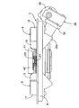
本発明の実施の形態について、添付の図1〜図7を参照しながら説明すると、先ず図1および図2において、四輪車両のたとえば左後輪にはドラムブレーキ5が設けられており、このドラムブレーキ5は、固定のバックプレート6と、前記左後輪とともに回転するブレーキドラム7の内周に摺接することを可能として前記バックプレート6内に配置される第1および第2のブレーキシュー8,9と、第1および第2のブレーキシュー8,9が拡張作動する力を発揮するようにして前記バックプレート6の上部に固定されるホイールシリンダ10と、第1および第2のブレーキシュー8,9および前記ブレーキドラム7間の間隙を自動的に調整する制動間隙自動調整手段11と、第1および第2のブレーキシュー8,9間に設けられるリターンスプリング12とを備える。
The embodiment of the present invention will be described with reference to FIGS. 1 to 7 attached herewith. First, in FIGS. 1 and 2, a
第1および第2のブレーキシュー8,9は、前記ブレーキドラム7の内周に沿うようにして弓形に形成されるウエブ13,14と、そのウエブ13,14の外周に直交するように連設されるリム15,16と、該リム15,16の外周に貼着されるライニング17,18とから成る。
The first and
前記ホイールシリンダ10が備える一対のピストン19の外端部は、第1および第2のブレーキシュー8,9の上端部で前記ウエブ13,14に対向するように配置される。また前記バックプレート6の下部には、第1および第2のブレーキシュー8,9の拡張、収縮時の支点となるようにしてアンカーブロック20が固設されており、前記ホイールシリンダ10は、ブレーキペダルで操作されるマスタシリンダ(図示せず)の出力液圧によって作動して、前記アンカーブロック20を支点として第1および第2のブレーキシュー8,9を拡張する側に駆動する力を発揮する。
The outer end portions of the pair of
第1および第2のブレーキシュー8,9における前記ウエブ13,14の下端部間には、それらのウエブ13,14の下端部を前記アンカーブロック20側に付勢するコイルスプリング21が設けられ、第1および第2のブレーキシュー8,9における前記ウエブ13,14の上端部間には、第1および第2のブレーキシュー8,9を収縮方向に付勢する前記リターンスプリング12が設けられる。
Between the lower ends of the
前記制動間隙自動調整手段11は、第1および第2のブレーキシュー8,9のウエブ13,14間に設けられるとともにアジャストギヤ28の回動によって伸長し得る収縮位置規制ストラット24と、前記アジャストギヤ28に係合する送り爪26aを有して第1および第2のブレーキシュー8,9のうち一方のブレーキシューである第2のブレーキシュー9の前記ウエブ14に回動可能に支持されるアジャストレバー26と、前記収縮位置規制ストラット24を伸長させる方向に前記アジャストギヤ28を回動させる側に前記アジャストレバー26を回動付勢するアジャストスプリング27とで構成される。
The automatic braking gap adjusting means 11 is provided between the
前記収縮位置規制ストラット24は、第1および第2のブレーキシュー8,9の収縮位置を規制するものであり、第1および第2のブレーキシュー8,9のうち第1のブレーキシュー8が備える前記ウエブ13の上部に係合する第1係合部29aを有する第1ロッド29と、第2のブレーキシュー9が備えるウエブ14の上部に係合する第2係合部30aを有して第1ロッド29と同軸に配置される第2ロッド30と、第1ロッド29に一端部が軸方向相対移動可能に挿入されるとともに第2ロッド30に他端部が同軸に螺合されるアジャストボルト31とを有しており、前記アジャストギヤ28は、第1および第2ロッド29,30間に配置されて前記アジャストボルト31の外周に形成される。
The contraction
第1のブレーキシュー8における前記ウエブ13の上部には第1係合部29aを係合させる第1係止凹部13aが設けられ、また第2のブレーキシュー9における前記ウエブ14の上部には第2係合部30aを係合させる第2係止凹部14aが設けられる。
A
前記アジャストギヤ28に係合する送り爪26aを有するアジャストレバー26は、第2のブレーキシュー9の前記ウエブ14に支軸25を介して回動可能に支持され、第2のブレーキシュー9の前記ウエブ14および前記アジャストレバー26間に前記アジャストスプリング27が設けられる。しかも前記アジャストスプリング27のばね力は、前記リターンスプリング12のばね力よりも小さく設定される。
An
このような制動間隙自動調整手段11によれば、第1および第2のブレーキシュー8,9が前記ホイールシリンダ10の作動によって拡張作動する際に前記ライニング17,18の摩耗に起因して一定値以上拡張した場合には、前記アジャストスプリング27のばね力によって前記アジャストレバー26が前記支軸25の軸線まわりに回動し、それによって前記アジャストギヤ28が回動するのに応じて前記収縮位置規制ストラット24の有効長さが増加補正される。
According to the automatic brake clearance adjusting means 11, when the first and
ところでドラムブレーキ5には、第1および第2のブレーキシュー8,9のうち他方のブレーキシューである第1のブレーキシュー8における前記ウエブ13に一端部が回動可能に軸支されるとともに前記収縮位置規制ストラット24の一端部に係合されるパーキングブレーキレバー32が付設される。
By the way, one end of the
前記パーキングブレーキレバー32は、第1のブレーキシュ−8における前記ウエブ13に正面視で一部が重なるようにして上下に延びるものであり、このパーキングブレーキレバー32の上端部は、第1のブレーキシュ−8の前記ウエブ13の上部にピン33を介して連結され、また該パーキングブレーキレバー32の上部には、前記収縮位置規制ストラット24が有する第1係合部29aが係合される。
The
車両のパーキング時には、前記パーキングブレーキレバー32が図1の反時計方向に回動、駆動されるものであり、このパーキングブレーキレバー32の回動によって、第2のブレーキシュー9に、当該ブレーキシュー9が有する前記ライニング18を前記ブレーキドラム7の内周に圧接させる方向の力が前記収縮位置規制ストラット24を介して作用する。さらに前記パーキングブレーキレバー32が図1の反時計方向に続けて回動、駆動されると、前記パーキングブレーキレバー32が前記収縮位置規制ストラット24の第1係合部29aとの係合点を支点として回動し、今度は、前記ピン33を介して第1のブレーキシュー8が拡張作動し、第1のブレーキシュー8の前記ライニング17が前記ブレーキドラム7の内周に圧接することになる。すなわち第1および第2のブレーキシュー8,9の前記ライニング17,18が前記ブレーキドラム7の内周に圧接してパーキングブレーキ状態が得られることになる。
When the vehicle is parked, the
前記パーキングブレーキレバー32は、電動アクチュエータ36が発揮する動力で回動駆動されるものであり、前記電動アクチュエータ36で牽引されるブレーキケーブル37が、該ブレーキケーブル37の牽引によって第2のブレーキシュー9の前記ウエブ14に前記収縮位置規制ストラット24を押しつけるように前記パーキングブレーキレバー32を回動駆動してパーキングブレーキ状態を得ることを可能として、前記パーキングブレーキレバー32の下部に接続される。
The
前記電動アクチュエータ36は、回転軸線を上下方向としてケーシング38に取り付けられる電動モータ40と、該電動モータ40の回転動力を直線方向の力に変換するようにして前記ケーシング38に内蔵される動力変換機構(図示せず)とを備える。前記ケーシング38は、前記ブレーキケーブル37を引き出すケーブル出口39を先端部に有する筒部38aを有するものであり、前記ケーブル出口39を前記バックプレート6内に臨ませるようにして前記バックプレート6の外面に取付けられる。
The
前記動力変換機構に連なる前記ブレーキケーブル37は、前記ケーブル出口39から前記バックプレート6内に引き出され、このブレーキケーブル37の先端部が、前記パーキングブレーキレバー32に接続される。しかも前記ケーシング38および前記パーキングブレーキレバー32間のブレーキケーブル37のうち前記ケーシング38側の一部が、前記ケーシング38および前記バックプレート6に対する固定位置に長手方向両端部が規制されるようにして前記バックプレート6内に配置されるアウターケーブル41で囲繞され、前記ブレーキケーブル37のうち前記アウターケーブル41および前記パーキングブレーキレバー32間の部分が、前記バックプレート6内に配置される蛇腹状のブーツ42で覆われる。
The brake cable 37 connected to the power conversion mechanism is pulled out from the
前記アウターケーブル41および前記ブーツ42を接続する第1ケーブルエンドキャップ46は、前記バックプレート6に設けられるアンカーブロック20で支持される。
A first
前記ブレーキケーブル37の先端部は、前記パーキングブレーキレバー32の下端部に係合する第2ケーブルエンドキャップ47にかしめ固定されており、前記ブーツ42の一端部は、前記第1ケーブルエンドキャップ46の他端部に嵌合され、前記ブーツ42の他端部は第2ケーブルエンドキャップ47に嵌合される。
The tip of the brake cable 37 is fixed by caulking to a second
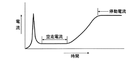
ところで前記電動アクチュエータ36における前記電動モータ40に所定電圧を印加したときに、前記電動モータ40に流れる電流は、図3で示すように変化するものであり、始動時に一時的に立ち上がる始動電流が流れた後に、電動モータ40および前記パーキングブレーキレバー32間のブレーキケーブル37の弛みを吸収する等によって電動モータ40に負荷がかからずに低下する空走電流の状態を経て電流が増加し、電動モータ40の出力および負荷が釣り合ったときに、電動モータ40はそれ以上回転できずに停止し、一定の停動電流となる。
By the way, when a predetermined voltage is applied to the
このような特性に基づけば、停動電流以上の電流が前記電動モータ40に通電されるような制御がなされれば良いことになるが、電動アクチュエータ36内のグリスの粘度が温度低下に応じて高くなること等によって、 電動モータ40の通電電流が同じであっても、前記電動アクチュエータ36の出力は温度に応じて変化するものである。たとえば前記電動モータ40の通電電流に対する電動アクチュエータ36の出力が高温になるほど大きくなる場合、すなわち前記ケーシング38に内蔵される動力変換機構において温度が高温になるほど効率が良くなる場合には、前記電動アクチュエータ36の出力は、温度に応じて図4で示すように変化する。このような電動アクチュエータ36において、たとえば温度0℃で所定の出力が得られるようにして設定電流を定めると、図5で示すように、温度0℃以下の斜線で示す領域では必要な出力が得られず、温度が低くなるほど設定電流よりも高い電流が必要となり、温度0℃を超えると、必要な出力を得るための電流は前記設定電流よりも低くなる。
Based on such characteristics, it is sufficient that the
そこで前記電動アクチュエータ36における前記電動モータ40の作動を制御する制御ユニットCは、温度を推定するとともに、その温度に応じて前記電動モータ40への通電を温度に応じて変化させるようにして前記電動モータ40の作動を制御するように構成される。
Therefore, the control unit C that controls the operation of the
図6において、前記制御ユニットCは、バッテリ50から供給される電力を受けて前記電動モータ40を駆動する電動モータ駆動手段51と、前記電動モータ40への通電電流を検出する電流検出手段52と、前記電動モータ40に第1の所定電圧を印加するように前記電動モータ駆動手段51の作動を制御する通常制御状態ならびに前記電動モータ40の作動開始後の第1の所定時間T1の経過後に前記電流検出手段52が第1の所定電流AAを検出するのに応じて前記第1の所定電圧よりも低い第2の所定電圧相当で前記電動モータ40に通電するようにしたPWM制御で前記電動モータ駆動手段51の作動を制御するPWM制御状態を切り替え可能とした作動制御手段53と、前記PWM制御状態での前記電流検出手段52の検出値に基づいて温度を判定するとともにその判定結果を前記作動制御手段53の制御に反映させる温度判定手段54とを備える。
In FIG. 6, the control unit C receives electric power supplied from the
前記第1の所定電流AAは、常温域で車両を勾配停止させ得る出力を前記電動モータ40が発揮する電流に設定される。
The first predetermined current AA is set to a current at which the
また前記電動モータ40の作動制御時の電流波形が、図7で示すものであるときに、前記第1の所定時間T1は、前記電動モータ40の始動時から始動電流が生じた後の空走電流の状態までの時間として設定される。
Further, when the current waveform during the operation control of the
前記温度判定手段54は、前記PWM制御状態で前記電動モータ40の通電電流が、所定温度のときの前記電動モータ40への通電電流値に対して一定もしくは減少するときには前記温度が所定温度以上であると判定し、前記PWM制御状態で前記電動モータ40の通電電流が、所定温度のときの前記電動モータ40への通電電流値に対して増加するときには前記温度が所定温度未満であると判定する。
The
ところで温度が所定温度の状態で電動モータ40の通電電流が第1の所定電流AAに達したときには、その通電電流は停動電流に達しており、図7の実線で示すように、電流は増加せず、電動モータ40も動かない。また温度が所定温度以上の温度であったときには、電動モータ40の通電電流が第1の所定電流AAに達した後でPWM制御に入ると、温度が高くなることによって電気抵抗値が大きくなるのに応じて、図7の破線で示すように、電流が低下する。すなわちPWM制御時に、前記電動モータ40の通電電流が、所定温度のときの前記電動モータ40への通電電流値に対して一定もしくは減少するときに、前記温度判定手段54は、前記温度が所定温度以上であると判定することになる。
By the way, when the energizing current of the
前記作動制御手段53は、前記電動モータ40の通電電流に対する前記電動アクチュエータ36の出力が高温になるほど大きくなる場合に、前記温度が前記所定温度以上の温度であると前記温度判定手段54が判定するのに応じて、前記電動モータ40の作動制御を停止する。
In the operation control means 53, the temperature determination means 54 determines that the temperature is equal to or higher than the predetermined temperature when the output of the
また温度が所定温度未満の温度であったときには、電動モータ40の通電電流が第1の所定電流AAに達した後でPWM制御に入ると、温度が低くなることによって電気抵抗値が大きくなるのに応じて、図7の二点鎖線で示すように、電流が第1の所定電流AAよりも増加する。すなわちPWM制御時に、前記電動モータ40の通電電流が、所定温度のときの前記電動モータ40への通電電流値に対して増加するときに、前記温度判定手段54は、前記温度が所定温度未満であると判定することになる。
Further, when the temperature is lower than the predetermined temperature, when the PWM control is started after the energization current of the
前記作動制御手段53は、前記電動モータ40の通電電流に対する前記電動アクチュエータ36の出力が高温になるほど大きくなる場合に、前記所定温度未満の温度であると前記温度判定手段54が判定したときに、前記PWM制御の開始後に第2の所定時間T2が経過するまで前記電動モータ40の通電電流が停動電流未満であった場合には、前記第1の所定電流AAよりも高い第2の所定電流ABに達するまで前記通常制御を実行する。
The operation control means 53, when the temperature determination means 54 determines that the temperature is lower than the predetermined temperature when the output of the
前記第2の所定電流ABは、低温域で車両を勾配停止させ得る出力を前記電動モータ40が発揮する電流に設定される。
Said 2nd predetermined electric current AB is set to the electric current which the said
次にこの実施の形態の作用について説明すると、電動アクチュエータ36における電動モータ40の作動を制御する制御ユニットCは、前記電動モータ40を駆動する電動モータ駆動手段51と、前記電動モータ40への通電電流を検出する電流検出手段52と、前記電動モータ40に第1の所定電圧を印加するように前記電動モータ駆動手段51の作動を制御する通常制御状態ならびに前記電動モータ40の作動開始後の第1の所定時間T1経過後に前記電流検出手段52が前記第1の所定電流AAを検出するのに応じて前記第1の所定電圧よりも低い第2の所定電圧相当で前記電動モータ40に通電するようにしたPWM制御で前記電動モータ駆動手段51の作動を制御するPWM制御状態を切り替え可能とした作動制御手段53と、前記PWM制御状態での前記電流検出手段52の検出値に基づいて温度を判定するとともにその判定結果を前記作動制御手段53の制御に反映させる温度判定手段54とを備え、温度判定手段54は、前記PWM制御状態で前記電動モータ40の通電電流が一定もしくは減少するときには前記温度が所定温度以上であると判定し、前記PWM制御状態で前記電動モータ40の通電電流が所定温度のときの前記電動モータ40への通電電流値に対して増加するときには前記温度が所定温度未満であると判定するので、低電流である空走電流ではなく電動モータ40に負荷をかけた状態での電流によって、温度センサを用いることなく、より正確な温度判定を行なうことができる。しかもPWM制御で電動モータ40に通電することで、第1の所定電流AAの通電時よりも低い電圧相当で電動モータ40が作動することになり、電動モータ40に大きな負荷がかかることはない。
Next, the operation of this embodiment will be described. The control unit C for controlling the operation of the
また前記電動モータ40の通電電流に対する前記電動アクチュエータ36の出力が高温になるほど大きくなる場合に、前記所定温度未満の温度であると前記温度判定手段54が判定したときに、前記PWM制御の開始後に第2の所定時間T2が経過するまで前記電動モータ40の通電電流が停動電流未満であったときに、前記作動制御手段53は、前記第1の所定電流AAよりも高い第2の所定電流ABに達するまで前記通常制御を実行するので、ブレーキケーブル37をさらに牽引するようにして、温度低下による駐車ブレーキ力の変化を抑制することができる。
When the output of the
また前記電動モータ40の通電電流に対する前記電動アクチュエータ36の出力が高温になるほど大きくなる場合に、前記所定温度以上の温度であると前記温度判定手段54が判定するのに応じて、前記作動制御手段53は前記電動モータ40の作動制御を停止するので、温度判定に基づく電動モータ40の作動制御を行なうことができ、温度による出力バラツキを考慮した制御が可能となる。
Further, when the output of the
また前記第1の所定電流AAが、常温域で車両を勾配停止させ得る出力を前記電動モータ40が発揮する電流に設定されるので、PWM制御の実行によって応答性が低下する虞があるが、温度判定時には常温域に対応した駐車ブレーキ力が発生しており、応答性が低下することはない。
Further, since the first predetermined current AA is set to a current that the
さらに前記第2の所定電流ABが、低温域で車両を勾配停止させ得る出力を前記電動モータ40が発揮する電流に設定されるので、温度判定の回数を最小限にすることができる。
Furthermore, since the second predetermined current AB is set to a current that the
上述の実施の形態の形態では、前記電動モータ40の通電電流に対する前記電動アクチュエータ36の出力が高温になるほど大きくなる場合について説明したが、本発明は、前記電動モータ40の通電電流に対する前記電動アクチュエータ36の出力が高温になるほど小さくなる場合にも適用することができる。その場合、前記所定温度未満の温度であると前記温度判定手段54が判定するのに応じて、前記作動制御手段53が前記電動モータ40の作動制御を停止し、前記所定温度以上の状態であると前記温度判定手段54が判定した状態で前記PWM制御の開始後に第2の所定時間T2が経過するまで前記電動モータ40の通電電流が停動電流未満であったときに、前記作動制御手段53が、前記所定電流AAよりも高い第2の所定電流AB(高温域で車両を勾配停止させ得る出力を前記電動モータ40が発揮する電流)に達するまで前記通常制御を実行するようにすればよい。そうすれば温度判定に基づく電動モータ40の作動制御を行なって温度による出力バラツキを考慮した制御が可能となるとともに、温度上昇時にブレーキケーブルをさらに牽引するようにして温度上昇による駐車ブレーキ力の変化を抑制することができる。
In the above-described embodiment, the case where the output of the
以上、本発明の実施の形態について説明したが、本発明は上記実施の形態に限定されるものではなく、特許請求の範囲に記載された本発明を逸脱することなく種々の設計変更を行うことが可能である。 Although the embodiments of the present invention have been described above, the present invention is not limited to the above-described embodiments, and various design changes can be made without departing from the present invention described in the claims. Is possible.
5・・・ドラムブレーキ
32・・・パーキングブレーキレバー
36・・・電動アクチュエータ
37・・・ブレーキケーブル
40・・・電動モータ
51・・・電動モータ駆動手段
52・・・電流検出手段
53・・・作動制御手段
54・・・温度判定手段
AA・・・所定電流
AB・・・第2の所定電流
T1・・・所定時間
T2・・・第2の所定時間
5 ...
Claims (8)
Priority Applications (1)
| Application Number | Priority Date | Filing Date | Title |
|---|---|---|---|
| JP2015205271A JP6562811B2 (en) | 2015-10-19 | 2015-10-19 | Brake device for vehicle |
Applications Claiming Priority (1)
| Application Number | Priority Date | Filing Date | Title |
|---|---|---|---|
| JP2015205271A JP6562811B2 (en) | 2015-10-19 | 2015-10-19 | Brake device for vehicle |
Publications (2)
| Publication Number | Publication Date |
|---|---|
| JP2017077739A JP2017077739A (en) | 2017-04-27 |
| JP6562811B2 true JP6562811B2 (en) | 2019-08-21 |
Family
ID=58665688
Family Applications (1)
| Application Number | Title | Priority Date | Filing Date |
|---|---|---|---|
| JP2015205271A Active JP6562811B2 (en) | 2015-10-19 | 2015-10-19 | Brake device for vehicle |
Country Status (1)
| Country | Link |
|---|---|
| JP (1) | JP6562811B2 (en) |
Families Citing this family (4)
| Publication number | Priority date | Publication date | Assignee | Title |
|---|---|---|---|---|
| CN110228469B (en) * | 2018-03-05 | 2021-06-15 | 上海汽车集团股份有限公司 | Vehicle control method, device and system |
| DE112019001565T5 (en) * | 2018-03-27 | 2021-01-14 | Hitachi Automotive Systems, Ltd. | Control device for an electric motor and braking device |
| JP7218487B2 (en) * | 2018-09-25 | 2023-02-07 | ダイハツ工業株式会社 | electric parking brake system |
| KR20210065717A (en) * | 2019-11-27 | 2021-06-04 | 주식회사 만도 | Electronic parking brake system and control method thereof |
-
2015
- 2015-10-19 JP JP2015205271A patent/JP6562811B2/en active Active
Also Published As
| Publication number | Publication date |
|---|---|
| JP2017077739A (en) | 2017-04-27 |
Similar Documents
| Publication | Publication Date | Title |
|---|---|---|
| JP5535924B2 (en) | Parking brake and method for operating it | |
| US8185287B2 (en) | Method for the operation of an electromechanically operable parking brake | |
| JP6562811B2 (en) | Brake device for vehicle | |
| JP3740007B2 (en) | Control device for vehicle brake | |
| JP4342469B2 (en) | Control device for vehicle brake | |
| JP5501462B2 (en) | Setting method of tightening force given by parking brake | |
| JP4998344B2 (en) | Parking brake control device | |
| KR101958503B1 (en) | Method, regulating and/or control unit, and parking brake having a regulating and/or control unit of said type for adjusting a parking brake in a vehicle | |
| KR101836628B1 (en) | Electro-mechanical brake system and control method thereof | |
| JP6661507B2 (en) | Electric actuator control device and electric parking brake device | |
| US20150041257A1 (en) | Method for providing the application force generated by a parking brake | |
| JP5234266B2 (en) | Disc brake device | |
| US10449935B2 (en) | Method for controlling a parking brake in a vehicle | |
| US9114792B2 (en) | Method for setting the clamping force exerted by a parking brake | |
| JP6243610B2 (en) | Method of providing clamping force applied by parking brake | |
| JP6811101B2 (en) | Electric parking brake device and brake device | |
| US9616864B2 (en) | Method and device for operating a braking device, braking device | |
| WO2015159591A1 (en) | Drum brake device | |
| US10759407B2 (en) | Electric parking brake device | |
| JP6596294B2 (en) | Brake device for vehicle | |
| CN110958963B (en) | Method for estimating braking force, parking-braking method and parking-braking system | |
| JP6471572B2 (en) | Electric parking brake device | |
| JP6011094B2 (en) | Parking brake control device | |
| EP4119811A1 (en) | Electric parking brake device | |
| JP2016176573A (en) | Brake device for vehicle |
Legal Events
| Date | Code | Title | Description |
|---|---|---|---|
| A621 | Written request for application examination |
Free format text: JAPANESE INTERMEDIATE CODE: A621 Effective date: 20180726 |
|
| TRDD | Decision of grant or rejection written | ||
| A977 | Report on retrieval |
Free format text: JAPANESE INTERMEDIATE CODE: A971007 Effective date: 20190627 |
|
| A01 | Written decision to grant a patent or to grant a registration (utility model) |
Free format text: JAPANESE INTERMEDIATE CODE: A01 Effective date: 20190703 |
|
| A61 | First payment of annual fees (during grant procedure) |
Free format text: JAPANESE INTERMEDIATE CODE: A61 Effective date: 20190723 |
|
| R150 | Certificate of patent or registration of utility model |
Ref document number: 6562811 Country of ref document: JP Free format text: JAPANESE INTERMEDIATE CODE: R150 |
|
| S111 | Request for change of ownership or part of ownership |
Free format text: JAPANESE INTERMEDIATE CODE: R313111 |
|
| R350 | Written notification of registration of transfer |
Free format text: JAPANESE INTERMEDIATE CODE: R350 |
|
| R250 | Receipt of annual fees |
Free format text: JAPANESE INTERMEDIATE CODE: R250 |