DE102012111488A1 - Method for producing a structural component, in particular for a bodywork - Google Patents
Method for producing a structural component, in particular for a bodywork Download PDFInfo
- Publication number
- DE102012111488A1 DE102012111488A1 DE102012111488.9A DE102012111488A DE102012111488A1 DE 102012111488 A1 DE102012111488 A1 DE 102012111488A1 DE 102012111488 A DE102012111488 A DE 102012111488A DE 102012111488 A1 DE102012111488 A1 DE 102012111488A1
- Authority
- DE
- Germany
- Prior art keywords
- support material
- carrier material
- thermoplastic
- composite
- carrier
- Prior art date
- Legal status (The legal status is an assumption and is not a legal conclusion. Google has not performed a legal analysis and makes no representation as to the accuracy of the status listed.)
- Ceased
Links
Images


Classifications
-
- B—PERFORMING OPERATIONS; TRANSPORTING
- B29—WORKING OF PLASTICS; WORKING OF SUBSTANCES IN A PLASTIC STATE IN GENERAL
- B29C—SHAPING OR JOINING OF PLASTICS; SHAPING OF MATERIAL IN A PLASTIC STATE, NOT OTHERWISE PROVIDED FOR; AFTER-TREATMENT OF THE SHAPED PRODUCTS, e.g. REPAIRING
- B29C43/00—Compression moulding, i.e. applying external pressure to flow the moulding material; Apparatus therefor
- B29C43/22—Compression moulding, i.e. applying external pressure to flow the moulding material; Apparatus therefor of articles of indefinite length
- B29C43/222—Compression moulding, i.e. applying external pressure to flow the moulding material; Apparatus therefor of articles of indefinite length characterised by the shape of the surface
-
- B—PERFORMING OPERATIONS; TRANSPORTING
- B29—WORKING OF PLASTICS; WORKING OF SUBSTANCES IN A PLASTIC STATE IN GENERAL
- B29C—SHAPING OR JOINING OF PLASTICS; SHAPING OF MATERIAL IN A PLASTIC STATE, NOT OTHERWISE PROVIDED FOR; AFTER-TREATMENT OF THE SHAPED PRODUCTS, e.g. REPAIRING
- B29C43/00—Compression moulding, i.e. applying external pressure to flow the moulding material; Apparatus therefor
- B29C43/02—Compression moulding, i.e. applying external pressure to flow the moulding material; Apparatus therefor of articles of definite length, i.e. discrete articles
- B29C43/021—Compression moulding, i.e. applying external pressure to flow the moulding material; Apparatus therefor of articles of definite length, i.e. discrete articles characterised by the shape of the surface
-
- B—PERFORMING OPERATIONS; TRANSPORTING
- B29—WORKING OF PLASTICS; WORKING OF SUBSTANCES IN A PLASTIC STATE IN GENERAL
- B29C—SHAPING OR JOINING OF PLASTICS; SHAPING OF MATERIAL IN A PLASTIC STATE, NOT OTHERWISE PROVIDED FOR; AFTER-TREATMENT OF THE SHAPED PRODUCTS, e.g. REPAIRING
- B29C43/00—Compression moulding, i.e. applying external pressure to flow the moulding material; Apparatus therefor
- B29C43/02—Compression moulding, i.e. applying external pressure to flow the moulding material; Apparatus therefor of articles of definite length, i.e. discrete articles
- B29C43/14—Compression moulding, i.e. applying external pressure to flow the moulding material; Apparatus therefor of articles of definite length, i.e. discrete articles in several steps
- B29C43/146—Compression moulding, i.e. applying external pressure to flow the moulding material; Apparatus therefor of articles of definite length, i.e. discrete articles in several steps for making multilayered articles
-
- B—PERFORMING OPERATIONS; TRANSPORTING
- B29—WORKING OF PLASTICS; WORKING OF SUBSTANCES IN A PLASTIC STATE IN GENERAL
- B29C—SHAPING OR JOINING OF PLASTICS; SHAPING OF MATERIAL IN A PLASTIC STATE, NOT OTHERWISE PROVIDED FOR; AFTER-TREATMENT OF THE SHAPED PRODUCTS, e.g. REPAIRING
- B29C43/00—Compression moulding, i.e. applying external pressure to flow the moulding material; Apparatus therefor
- B29C43/22—Compression moulding, i.e. applying external pressure to flow the moulding material; Apparatus therefor of articles of indefinite length
- B29C43/224—Compression moulding, i.e. applying external pressure to flow the moulding material; Apparatus therefor of articles of indefinite length having a profiled section, e.g. tubes, rods
-
- B—PERFORMING OPERATIONS; TRANSPORTING
- B29—WORKING OF PLASTICS; WORKING OF SUBSTANCES IN A PLASTIC STATE IN GENERAL
- B29C—SHAPING OR JOINING OF PLASTICS; SHAPING OF MATERIAL IN A PLASTIC STATE, NOT OTHERWISE PROVIDED FOR; AFTER-TREATMENT OF THE SHAPED PRODUCTS, e.g. REPAIRING
- B29C43/00—Compression moulding, i.e. applying external pressure to flow the moulding material; Apparatus therefor
- B29C43/22—Compression moulding, i.e. applying external pressure to flow the moulding material; Apparatus therefor of articles of indefinite length
- B29C43/28—Compression moulding, i.e. applying external pressure to flow the moulding material; Apparatus therefor of articles of indefinite length incorporating preformed parts or layers, e.g. compression moulding around inserts or for coating articles
-
- B—PERFORMING OPERATIONS; TRANSPORTING
- B29—WORKING OF PLASTICS; WORKING OF SUBSTANCES IN A PLASTIC STATE IN GENERAL
- B29C—SHAPING OR JOINING OF PLASTICS; SHAPING OF MATERIAL IN A PLASTIC STATE, NOT OTHERWISE PROVIDED FOR; AFTER-TREATMENT OF THE SHAPED PRODUCTS, e.g. REPAIRING
- B29C43/00—Compression moulding, i.e. applying external pressure to flow the moulding material; Apparatus therefor
- B29C43/22—Compression moulding, i.e. applying external pressure to flow the moulding material; Apparatus therefor of articles of indefinite length
- B29C43/30—Making multilayered or multicoloured articles
- B29C43/305—Making multilayered articles
-
- B—PERFORMING OPERATIONS; TRANSPORTING
- B29—WORKING OF PLASTICS; WORKING OF SUBSTANCES IN A PLASTIC STATE IN GENERAL
- B29C—SHAPING OR JOINING OF PLASTICS; SHAPING OF MATERIAL IN A PLASTIC STATE, NOT OTHERWISE PROVIDED FOR; AFTER-TREATMENT OF THE SHAPED PRODUCTS, e.g. REPAIRING
- B29C43/00—Compression moulding, i.e. applying external pressure to flow the moulding material; Apparatus therefor
- B29C43/32—Component parts, details or accessories; Auxiliary operations
- B29C43/44—Compression means for making articles of indefinite length
- B29C43/48—Endless belts
-
- B—PERFORMING OPERATIONS; TRANSPORTING
- B32—LAYERED PRODUCTS
- B32B—LAYERED PRODUCTS, i.e. PRODUCTS BUILT-UP OF STRATA OF FLAT OR NON-FLAT, e.g. CELLULAR OR HONEYCOMB, FORM
- B32B37/00—Methods or apparatus for laminating, e.g. by curing or by ultrasonic bonding
- B32B37/08—Methods or apparatus for laminating, e.g. by curing or by ultrasonic bonding characterised by the cooling method
-
- B—PERFORMING OPERATIONS; TRANSPORTING
- B32—LAYERED PRODUCTS
- B32B—LAYERED PRODUCTS, i.e. PRODUCTS BUILT-UP OF STRATA OF FLAT OR NON-FLAT, e.g. CELLULAR OR HONEYCOMB, FORM
- B32B37/00—Methods or apparatus for laminating, e.g. by curing or by ultrasonic bonding
- B32B37/10—Methods or apparatus for laminating, e.g. by curing or by ultrasonic bonding characterised by the pressing technique, e.g. using action of vacuum or fluid pressure
- B32B37/1027—Pressing using at least one press band
-
- B—PERFORMING OPERATIONS; TRANSPORTING
- B29—WORKING OF PLASTICS; WORKING OF SUBSTANCES IN A PLASTIC STATE IN GENERAL
- B29C—SHAPING OR JOINING OF PLASTICS; SHAPING OF MATERIAL IN A PLASTIC STATE, NOT OTHERWISE PROVIDED FOR; AFTER-TREATMENT OF THE SHAPED PRODUCTS, e.g. REPAIRING
- B29C43/00—Compression moulding, i.e. applying external pressure to flow the moulding material; Apparatus therefor
- B29C43/32—Component parts, details or accessories; Auxiliary operations
- B29C43/44—Compression means for making articles of indefinite length
- B29C43/48—Endless belts
- B29C2043/483—Endless belts cooperating with a second endless belt, i.e. double band presses
-
- B—PERFORMING OPERATIONS; TRANSPORTING
- B29—WORKING OF PLASTICS; WORKING OF SUBSTANCES IN A PLASTIC STATE IN GENERAL
- B29C—SHAPING OR JOINING OF PLASTICS; SHAPING OF MATERIAL IN A PLASTIC STATE, NOT OTHERWISE PROVIDED FOR; AFTER-TREATMENT OF THE SHAPED PRODUCTS, e.g. REPAIRING
- B29C43/00—Compression moulding, i.e. applying external pressure to flow the moulding material; Apparatus therefor
- B29C43/02—Compression moulding, i.e. applying external pressure to flow the moulding material; Apparatus therefor of articles of definite length, i.e. discrete articles
- B29C43/18—Compression moulding, i.e. applying external pressure to flow the moulding material; Apparatus therefor of articles of definite length, i.e. discrete articles incorporating preformed parts or layers, e.g. compression moulding around inserts or for coating articles
-
- B—PERFORMING OPERATIONS; TRANSPORTING
- B29—WORKING OF PLASTICS; WORKING OF SUBSTANCES IN A PLASTIC STATE IN GENERAL
- B29C—SHAPING OR JOINING OF PLASTICS; SHAPING OF MATERIAL IN A PLASTIC STATE, NOT OTHERWISE PROVIDED FOR; AFTER-TREATMENT OF THE SHAPED PRODUCTS, e.g. REPAIRING
- B29C69/00—Combinations of shaping techniques not provided for in a single one of main groups B29C39/00 - B29C67/00, e.g. associations of moulding and joining techniques; Apparatus therefore
-
- B—PERFORMING OPERATIONS; TRANSPORTING
- B29—WORKING OF PLASTICS; WORKING OF SUBSTANCES IN A PLASTIC STATE IN GENERAL
- B29K—INDEXING SCHEME ASSOCIATED WITH SUBCLASSES B29B, B29C OR B29D, RELATING TO MOULDING MATERIALS OR TO MATERIALS FOR MOULDS, REINFORCEMENTS, FILLERS OR PREFORMED PARTS, e.g. INSERTS
- B29K2101/00—Use of unspecified macromolecular compounds as moulding material
- B29K2101/12—Thermoplastic materials
-
- B—PERFORMING OPERATIONS; TRANSPORTING
- B29—WORKING OF PLASTICS; WORKING OF SUBSTANCES IN A PLASTIC STATE IN GENERAL
- B29L—INDEXING SCHEME ASSOCIATED WITH SUBCLASS B29C, RELATING TO PARTICULAR ARTICLES
- B29L2031/00—Other particular articles
- B29L2031/30—Vehicles, e.g. ships or aircraft, or body parts thereof
- B29L2031/3002—Superstructures characterized by combining metal and plastics, i.e. hybrid parts
-
- B—PERFORMING OPERATIONS; TRANSPORTING
- B32—LAYERED PRODUCTS
- B32B—LAYERED PRODUCTS, i.e. PRODUCTS BUILT-UP OF STRATA OF FLAT OR NON-FLAT, e.g. CELLULAR OR HONEYCOMB, FORM
- B32B2311/00—Metals, their alloys or their compounds
-
- B—PERFORMING OPERATIONS; TRANSPORTING
- B32—LAYERED PRODUCTS
- B32B—LAYERED PRODUCTS, i.e. PRODUCTS BUILT-UP OF STRATA OF FLAT OR NON-FLAT, e.g. CELLULAR OR HONEYCOMB, FORM
- B32B2398/00—Unspecified macromolecular compounds
- B32B2398/20—Thermoplastics
-
- B—PERFORMING OPERATIONS; TRANSPORTING
- B32—LAYERED PRODUCTS
- B32B—LAYERED PRODUCTS, i.e. PRODUCTS BUILT-UP OF STRATA OF FLAT OR NON-FLAT, e.g. CELLULAR OR HONEYCOMB, FORM
- B32B2605/00—Vehicles
- B32B2605/08—Cars
-
- B—PERFORMING OPERATIONS; TRANSPORTING
- B32—LAYERED PRODUCTS
- B32B—LAYERED PRODUCTS, i.e. PRODUCTS BUILT-UP OF STRATA OF FLAT OR NON-FLAT, e.g. CELLULAR OR HONEYCOMB, FORM
- B32B37/00—Methods or apparatus for laminating, e.g. by curing or by ultrasonic bonding
- B32B37/06—Methods or apparatus for laminating, e.g. by curing or by ultrasonic bonding characterised by the heating method
-
- B—PERFORMING OPERATIONS; TRANSPORTING
- B32—LAYERED PRODUCTS
- B32B—LAYERED PRODUCTS, i.e. PRODUCTS BUILT-UP OF STRATA OF FLAT OR NON-FLAT, e.g. CELLULAR OR HONEYCOMB, FORM
- B32B37/00—Methods or apparatus for laminating, e.g. by curing or by ultrasonic bonding
- B32B37/14—Methods or apparatus for laminating, e.g. by curing or by ultrasonic bonding characterised by the properties of the layers
- B32B37/16—Methods or apparatus for laminating, e.g. by curing or by ultrasonic bonding characterised by the properties of the layers with all layers existing as coherent layers before laminating
- B32B37/20—Methods or apparatus for laminating, e.g. by curing or by ultrasonic bonding characterised by the properties of the layers with all layers existing as coherent layers before laminating involving the assembly of continuous webs only
- B32B37/203—One or more of the layers being plastic
Abstract
Die Erfindung betrifft ein Verfahren zum Herstellen eines Strukturbauteils (B, B'), insbesondere eines Strukturbauteils für eine Karosserie, bei dem ein flächiges Trägermaterial (T1, T2, T3, T4) aus Metall, thermoplastischem Kunststoff und/oder faserverstärktem thermoplastischem Kunststoff zu einem dreidimensionalen Bauteil umgeformt wird, und bei dem das Trägermaterial (T1, T2, T3, T4) mit Stützmaterial (S, S') aus thermoplastischem Kunststoff versehen wird, so dass das Trägermaterial und das Stützmaterial einen stoffschlüssigen Materialverbund bilden. Um die Anzahl der Fertigungsschritte eines solchen Verfahrens zu reduzieren und die Produktivität des Verfahrens zu erhöhen, sieht die Erfindung vor, dass der aus dem Trägermaterial (T1, T2, T3, T4) und dem Stützmaterial (S, S') aufgebaute Materialverbund vor dem Umformen des Trägermaterials (T1, T2, T3, T4) zu dem dreidimensionalen Bauteil (B, B') hergestellt wird, dass der Materialverbund (W) vor dem Umformen erhitzt wird, um eine Umformung des thermoplastischen Kunststoffs zu ermöglichen, dass während des Umformens des Materialverbundes eine Rippenstruktur (RS) in das Stützmaterial (S, S') eingeprägt wird, und dass das dreidimensionale, die Rippenstruktur (RS) aufweisende Bauteil (B, B') temperiert, vorzugsweise gekühlt wird.The invention relates to a method for producing a structural component (B, B '), in particular a structural component for a body, in which a flat carrier material (T1, T2, T3, T4) made of metal, thermoplastic and / or fiber-reinforced thermoplastic is made into one three-dimensional component is reshaped, and in which the carrier material (T1, T2, T3, T4) is provided with support material (S, S ') made of thermoplastic, so that the carrier material and the support material form a material bond. In order to reduce the number of manufacturing steps of such a method and to increase the productivity of the method, the invention provides that the composite material built up from the carrier material (T1, T2, T3, T4) and the support material (S, S ') before the Forming the carrier material (T1, T2, T3, T4) to the three-dimensional component (B, B ') is made that the material composite (W) is heated before the forming in order to enable the thermoplastic to be formed during the forming of the composite material, a rib structure (RS) is embossed into the support material (S, S '), and that the three-dimensional component (B, B') having the rib structure (RS) is tempered, preferably cooled.
Description
Die Erfindung betrifft ein Verfahren zum Herstellen eines Strukturbauteils, insbesondere eines Strukturbauteils für eine Karosserie, bei dem ein flächiges Trägermaterial aus Metall, thermoplastischem Kunststoff und/oder faserverstärktem thermoplastischem Kunststoff zu einem dreidimensionalen Bauteil umgeformt wird, und bei dem das Trägermaterial mit Stützmaterial aus thermoplastischem Kunststoff versehen wird, so dass das Trägermaterial und das Stützmaterial einen stoffschlüssigen Materialverbund bilden.The invention relates to a method for producing a structural component, in particular a structural component for a body, in which a planar carrier material made of metal, thermoplastic material and / or fiber-reinforced thermoplastic material is formed into a three-dimensional component, and in which the carrier material with support material made of thermoplastic material is provided so that the carrier material and the support material form a cohesive composite material.
Der Begriff Strukturbauteil umfasst im vorliegenden Kontext insbesondere Leichtbauteile und Stützbauteile für Fahrzeuge.The term structural component comprises in the present context in particular lightweight components and support components for vehicles.
Aus der
Die
Diese bekannten Verfahren zur Herstellung von Leichtbauteilen in Hybridform erfordern relativ viele Fertigungsschritte bzw. die Kombination mehrerer Prozesse.These known methods for producing lightweight components in hybrid form require relatively many manufacturing steps or the combination of multiple processes.
Davon ausgehend lag der vorliegenden Erfindung die Aufgabe zugrunde, ein Verfahren der eingangs genannten Art anzugeben, das relativ wenige Fertigungsschritte erfordert und eine relativ hohe Produktivität bietet.On this basis, the present invention has the object to provide a method of the type mentioned, which requires relatively few manufacturing steps and provides a relatively high productivity.
Zur Lösung dieser Aufgabe wird ein Verfahren mit den Merkmalen des Anspruchs 1 vorgeschlagen.To solve this problem, a method with the features of claim 1 is proposed.
Das erfindungsgemäße Verfahren ist dadurch gekennzeichnet, dass der Materialverbund aus Trägermaterial und Stützmaterial vor dem Umformen des Trägermaterials zu dem dreidimensionalen Bauteil hergestellt wird, dass der Materialverbund vor dem Umformen erhitzt wird, um eine Umformung des thermoplastischen Kunststoffs zu ermöglichen, dass während des Umformens des Materialverbundes eine Rippenstruktur in das Stützmaterial eingeprägt wird, und dass das dreidimensionale, die Rippenstruktur aufweisende Bauteil temperiert, vorzugsweise gekühlt wird.The inventive method is characterized in that the material composite of carrier material and support material is made prior to forming the carrier material to the three-dimensional component, that the composite material is heated prior to forming to allow a transformation of the thermoplastic material that during the forming of the composite material a rib structure is impressed in the support material, and that the three-dimensional, the rib structure having component tempered, preferably cooled.
Das erfindungsgemäße Verfahren basiert auf der Idee, ein fertig konsolidiertes Halbzeug zu schaffen, das in einem thermischen Umformprozess zu einem fertigen Strukturbauteil mit der gewünschten Endgeometrie weiterverarbeitet wird. Der thermische Umformprozess kann dabei gängige Operationsstufen wie Lochen, Schneiden und/oder Abstellen beinhalten. Dementsprechend sieht eine bevorzugte Ausgestaltung des erfindungsgemäßen Verfahrens vor, dass das die Rippenstruktur aufweisende Bauteil beschnitten, gelocht und/oder auf Endkontur abgestellt wird.The inventive method is based on the idea to create a finished consolidated semi-finished, which is further processed in a thermal forming process to a finished structural component with the desired final geometry. The thermal forming process can involve common operating stages such as punching, cutting and / or stopping. Accordingly, a preferred embodiment of the method according to the invention provides that the component having the rib structure is trimmed, perforated and / or placed on the final contour.
Dadurch, dass das Einformen der Rippenstruktur in das Stützmaterial zeitlich parallel zu dem Umformen des flächigen Trägermaterials durchgeführt wird, ist die Anzahl der Fertigungsschritte bei dem erfindungsgemäßen Verfahren erheblich verringert. Insbesondere wird dadurch eine erhöhte Produktivität ermöglicht bzw. erzielt.Due to the fact that the molding of the rib structure into the support material is carried out in parallel to the forming of the sheet-like support material, the number of production steps in the method according to the invention is considerably reduced. In particular, this enables or achieves increased productivity.
Als flächiges Trägermaterial wird bei dem erfindungsgemäßen Verfahren Metallblech, thermoplastisches Tafel- oder Flachmaterial und/oder faserverstärktes, thermoplastisches Tafel- oder Flachmaterial (sogenanntes Organoblech) verwendet. Das Trägermaterial kann dabei ein- oder mehrlagig, insbesondere zweilagig oder als Sandwichmaterial ausgebildet sein. Die Lagen des mehrlagigen Trägermaterials bestehen vorzugsweise aus unterschiedlichen Materialien, beispielsweise aus Metall und thermoplastischem Kunststoff mit oder ohne Faserverstärkung. Des Weiteren umfasst das erfindungsgemäße Verfahren Ausführungsformen, bei denen das flächige Trägermaterial als Bandmaterial oder als Zuschnitt, zum Beispiel in Form einer Platine verarbeitet wird.As a sheet-like support material in the inventive method sheet metal, thermoplastic sheet or flat material and / or fiber-reinforced thermoplastic sheet or flat material (so-called organo sheet) is used. The carrier material can be one or more layers, in particular two-ply or be formed as a sandwich material. The layers of the multilayer carrier material are preferably made of different materials, for example of metal and thermoplastic material with or without fiber reinforcement. Furthermore, the method according to the invention comprises embodiments in which the planar carrier material is processed as a strip material or as a blank, for example in the form of a circuit board.
Das Trägermaterial hat insbesondere die Funktion, die Geometrie (Form) des fertigenden Strukturbauteils zu definieren. So kann beispielsweise Metallblech als Trägermaterial die Außenhaut des erfindungsgemäß hergestellten Strukturbauteils definieren. Des Weiteren verleiht das ein- oder mehrlagige Trägermaterial dem erfindungsgemäß hergestellten Strukturbauteil ein bestimmtes Maß an Steifigkeit und Festigkeit, welches jedoch allein genommen für den vorgesehenen Einsatzzweck des Strukturbauteil in der Regel nicht ausreichend ist. Zur Sicherstellung einer ausreichenden Steifigkeit und Festigkeit des Strukturbauteils dient in Ergänzung zu dem umgeformten Trägermaterial das Stützmaterial mit der darin eingeformten Rippenstruktur.In particular, the carrier material has the function of defining the geometry (shape) of the finished structural component. For example, metal sheet as a carrier material can define the outer skin of the structural component produced according to the invention. Furthermore, the single-layer or multi-layered carrier material imparts a certain degree of rigidity and strength to the structural component produced according to the invention, which alone, however, is generally insufficient for the intended intended use of the structural component. In order to ensure sufficient rigidity and strength of the structural component, the support material with the rib structure formed therein serves in addition to the formed carrier material.
Damit das erfindungsgemäß hergestellte Strukturbauteil ein hohes Energieaufnahmevermögen (Stoßenergieabsorptionsvermögen) aufweist, wird für dessen Trägermaterial vorzugsweise faserverstärkter thermoplastischer Kunststoff (Organoblech) verwendet, wobei das Trägermaterial einschichtig aber auch mehrschichtiger, insbesondere als sandwichartiger Materialverbund ausgebildet sein kann, und wobei eine der Lagen (Schichten) des mehrschichtigen Materialverbundes vorzugsweise aus Metall, besonders bevorzugt aus Stahl, beispielsweise verzinktem Stahlblech besteht.In order for the structural component produced according to the invention to have a high energy absorption capacity (impact energy absorption capacity), fiber-reinforced thermoplastic material (organic sheet) is preferably used for the carrier material, wherein the carrier material may be single-layered but also multi-layered, in particular as a sandwiched material composite, and one of the layers (layers) of the multilayer material composite, preferably made of metal, particularly preferably of steel, for example galvanized sheet steel.
Sofern in dem erfindungsgemäßen Verfahren faserverstärkter thermoplastischer Kunststoff als Trägermaterial bzw. neben Metall als zusätzliches Trägermaterial verwendet wird, so enthält das Trägermaterial Lang-, Kurz- und/oder Endlosfasern aus anorganischem und/oder organischem Material. Unter Kurzfasern werden dabei Fasern mit einer Länge im Bereich von 0,1 bis 1 mm, unter Langfasern Fasern mit einer Länge im Bereich von 1 mm bis 50 mm, und unter Endlosfasern Fasern mit einer Faserlänge größer 50 mm verstanden.If in the method according to the invention fiber-reinforced thermoplastic material is used as the carrier material or in addition to metal as an additional carrier material, the carrier material contains long, short and / or continuous fibers of inorganic and / or organic material. Short fibers mean fibers with a length in the range of 0.1 to 1 mm, long fibers fibers with a length in the range of 1 mm to 50 mm, and continuous fibers with a fiber length of more than 50 mm.
Bei den anorganischen Fasern (Verstärkungsfasern) handelt es sich vorzugsweise um Glas-, Keramik- und/oder Basaltfasern. Die organischen Fasern (Verstärkungsfasern) bestehen dagegen beispielsweise aus Aramid-, Nylon- und/oder Kohlenstofffasern.The inorganic fibers (reinforcing fibers) are preferably glass, ceramic and / or basalt fibers. By contrast, the organic fibers (reinforcing fibers) consist, for example, of aramid, nylon and / or carbon fibers.
Bei dem thermoplastischen Kunststoff des Trägermaterials bzw. des Stützmaterials handelt es sich vorzugsweise um Polyamid (PA), Polypropylen (PP), Polycarbonat (PC), Polyethersulfon (PES), Acrylnitril-Butadien-Styrol (ABS), Styrol-Acrylnitril-Copolymerisat (SAN), Polyoxymethylen (POM), Polytetrafluorethylen (PTFE), thermoplastisches Polyurethan (TPU), Polyethylen (PE), Polybutylenterephthalat (PBT) und/oder deren Mischungen. Vorzugsweise weist der in dem erfindungsgemäßen Verfahren verwendete thermoplastische Kunststoff eine Temperaturbeständigkeit von mindestens 80°C, besonders bevorzugt mindestens 100°C auf.The thermoplastic material of the carrier material or of the support material is preferably polyamide (PA), polypropylene (PP), polycarbonate (PC), polyethersulfone (PES), acrylonitrile-butadiene-styrene (ABS), styrene-acrylonitrile copolymer ( SAN), polyoxymethylene (POM), polytetrafluoroethylene (PTFE), thermoplastic polyurethane (TPU), polyethylene (PE), polybutylene terephthalate (PBT) and / or mixtures thereof. Preferably, the thermoplastic used in the process according to the invention has a temperature resistance of at least 80 ° C, more preferably at least 100 ° C.
Das thermoplastische Stützmaterial wird mit einer Schichtdicke auf das flächige, ein- oder mehrlagige Trägermaterial aufgebracht, die je nach Anwendungsfall entsprechend der zu erzeugenden Rippendicke und/oder Rippenggröße ausgelegt wird, vorzugsweise mindestens das Zweifache, besonders bevorzugt mindestens das Dreifache der Dicke des flächigen, ein- oder mehrlagigen Trägermaterials beträgt.The thermoplastic support material is applied with a layer thickness on the flat, single or multilayer carrier material, which is designed according to the application according to the rib thickness and / or Rippenggröße to be produced, preferably at least twice, more preferably at least three times the thickness of the sheet - or multilayer carrier material.
Das Stützmaterial kann in mehreren Lagen auf das Trägermaterial aufgebracht werden. Eine weitere Ausgestaltung des erfindungsgemäßen Verfahrens ist dadurch gekennzeichnet, dass die Lagen des Stützmaterials mit unterschiedlicher Materialzusammensetzung, unterschiedlicher Flächengröße und/oder unterschiedlicher Schichtdicke auf das Trägermaterial aufgebracht werden. Auf diese Weise lassen sich aus dem erfindungsgemäß hergestellten Materialverbund (Halbzeug) Strukturteile mit optimiertem Stoßenergieaufnahmevermögen bzw. optimierter Steifigkeit bei relativ geringem Bauteilgewicht erzeugen.The support material can be applied to the carrier material in several layers. A further embodiment of the method according to the invention is characterized in that the layers of the support material with different material composition, different area size and / or different layer thickness are applied to the carrier material. In this way, it is possible to produce structural parts with optimized impact energy absorption capacity or optimized rigidity with a relatively low component weight from the material composite (semi-finished product) produced according to the invention.
Eine weitere vorteilhafte Ausgestaltung des erfindungsgemäßen Verfahrens ist dadurch gekennzeichnet, dass das Stützmaterial auf definierte Teilflächenbereiche des Trägermaterials aufgebracht wird. Auch diese Ausgestaltung ist für eine Optimierung der Steifigkeit und/oder des Stoßenergieaufnahmevermögens des Strukturbauteils bei relativ geringem oder minimiertem Bauteilgewicht von Vorteil. Hierzu sieht eine weitere Ausgestaltung des Verfahrens vor, dass auf verschiedene Teilflächenbereiche des Trägermaterials das Stützmaterial mit unterschiedlicher Materialzusammensetzung und/oder unterschiedlicher Schichtdicke aufgebracht wird.A further advantageous embodiment of the method according to the invention is characterized in that the support material is applied to defined partial surface areas of the carrier material. This refinement is also advantageous for optimizing the rigidity and / or the impact energy absorption capacity of the structural component with a relatively low or minimized component weight. For this purpose, a further embodiment of the method provides that the support material with different material composition and / or different layer thickness is applied to different partial surface areas of the carrier material.
Zur Optimierung der Steifigkeit und/oder des Stoßenergieaufnahmevermögens des Strukturbauteils kann gemäß einer weiteren vorteilhaften Ausgestaltung des erfindungsgemäßen Verfahrens das Stützmaterial in Form eines einzelnen Streifens oder in Form mehrerer Streifen auf das Trägermaterial aufgebracht werden, und zwar so, dass der jeweilige Streifen einen bestimmten Teilflächenbereich des Trägermaterials bedeckt.To optimize the rigidity and / or the impact energy absorption capacity of the structural component, the support material can be applied in the form of a single strip or in the form of several strips on the carrier material, in such a way that the respective strips covered a certain partial surface area of the carrier material.
Eine weitere vorteilhafte Ausgestaltung des erfindungsgemäßen Verfahrens besteht darin, dass das Umformen des aus dem flächigen Trägermaterial und dem Stützmaterial aufgebauten Materialverbundes und das Temperieren des Bauteils mittels eines temperierten Umformwerkzeuges durchgeführt werden. Bei dem Umformwerkzeug kann es sich um ein „kaltes”, konventionelles Werkzeug handeln, es kann aber auch temperierbar, d. h. aktiv kühlbar und/oder erwärmbar sein, je nach Bedarf. Hierdurch kann die Produktivität des Verfahrens weiter gesteigert werden.A further advantageous embodiment of the method according to the invention consists in that the forming of the composite material composed of the flat carrier material and the supporting material and the tempering of the component are carried out by means of a tempered forming tool. The forming tool can be a "cold", conventional tool, but it can also be tempered, d. H. be actively coolable and / or heatable, as needed. As a result, the productivity of the process can be further increased.
Eine besonders hohe Produktivität lässt sich insbesondere dann erzielen, wenn gemäß einer weiteren Ausgestaltung des erfindungsgemäßen Verfahrens der aus dem Trägermaterial und dem Stützmaterial aufgebaute Materialverbund in einem kontinuierlichen Bandlaufprozess hergestellt wird, wobei bandförmiges Trägermaterial und bandförmiges Stützmaterial miteinander stoffschlüssig verbunden werden. Diese Ausgestaltung eignet sich insbesondere für die Herstellung von länglichen, profilförmigen Strukturbauteilen, zum Beispiel von Seitenaufprallträgern, Front- sowie Heckstoßfängern, Schwellern und/oder Fahrzeugdachsäulen.A particularly high productivity can be achieved in particular if, according to a further embodiment of the method according to the invention, the material composite constructed from the carrier material and the support material is produced in a continuous strip running process, wherein band-shaped carrier material and band-shaped support material are connected to one another in a material-locking manner. This embodiment is particularly suitable for the production of elongated, profile-shaped structural components, for example of side impact beams, front and rear bumpers, sills and / or vehicle roof pillars.
Der im kontinuierlichen Bandlaufprozess hergestellte Materialverbund kann zu einem Coil aufgewickelt oder zu Platinen abgelängt werden, wobei das jeweilige Coil bzw. die Platinen anschließend zu dem gewünschten Strukturbauteil weiterverarbeitet werden können.The composite material produced in the continuous strip running process can be wound into a coil or cut to form blanks, wherein the respective coil or blanks can then be further processed to the desired structural component.
Eine andere Ausgestaltung des erfindungsgemäßen Verfahrens sieht vor, dass der aus dem Trägermaterial und dem Stützmaterial aufgebaute Materialverbund in einem diskontinuierlichen Laminier- und/oder Materialauftragsprozess hergestellt wird, wobei auf vorkonfektionierte Trägermaterialplatinen zumindest partiell Stützmaterial in der Weise aufgebracht wird, dass eine stoffschlüssige Verbindung zwischen der jeweiligen Trägermaterialplatine und dem darauf aufgebrachten Stützmaterial erzeugt wird. Diese Ausgestaltung ist insbesondere dann vorteilhaft, wenn das Stützmaterial auf einen oder mehrere definierte Teilflächenbereiche des Trägermaterials aufgebracht werden soll. Auf diese Weise können maßgeschneiderte Stützmaterial-Flächenabschnitte (Zuschnitte) auf einen oder mehrere definierte Teilflächenbereiche des Trägermaterials aufgebracht werden. Die maßgeschneiderten Stützmaterial-Flächenabschnitte können sich dabei in ihrer Form (Geometrie), Schichtdicke und/oder Materialbeschaffenheit unterscheiden.Another embodiment of the method according to the invention provides that the material composite constructed from the carrier material and the support material is produced in a discontinuous lamination and / or material application process, wherein support material is at least partially applied to prefabricated carrier material plates in such a way that a cohesive connection between the respective carrier board and the support material applied thereto. This embodiment is particularly advantageous when the support material is to be applied to one or more defined partial surface areas of the carrier material. In this way, tailor-made support material surface sections (blanks) can be applied to one or more defined partial surface regions of the carrier material. The tailor-made support material surface sections may differ in their shape (geometry), layer thickness and / or material properties.
Der Aufbau des aus dem flächigen Trägermaterial und dem thermoplastischen Stützmaterial hergestellten Materialverbundes (Halbzeuges) kann bei dem erfindungsgemäßen Verfahren in unterschiedlicher Weise ausgeführt sein bzw. werden. In einer Ausgestaltung des Verfahrens ist vorgesehen, dass das Stützmaterial in Form einer homogenen, flächigen Schicht auf das Trägermaterial aufgebracht wird. Diese Ausgestaltung lässt sich prozesstechnisch relativ einfach mittels eines kontinuierlichen Bandlaufprozess, aber bei Verwendung von vorkonfektionierten Platinen bzw. Tafeln in einem Patch- und Laminierprozess verwirklichen. Unter „Patchen” bzw. Patchprozess wird hier das Aufbringen von zugeschnittenen bzw. maßgeschneiderten Stützmaterial-Flächenstücken verstanden.The construction of the composite material (semifinished product) produced from the flat carrier material and the thermoplastic support material can be or are carried out in different ways in the method according to the invention. In one embodiment of the method, it is provided that the support material is applied to the carrier material in the form of a homogeneous, flat layer. This refinement can be implemented relatively simply in terms of process technology by means of a continuous strip running process, but when prefabricated blanks or panels are used in a patching and laminating process. The term "patching" or "patching process" here refers to the application of tailored or customized support material surface pieces.
Nach einer weiteren Ausgestaltung des Verfahrens ist vorgesehen, dass als Stützmaterial faserverstärkter thermoplastischer Kunststoff verwendet wird. Aus dem so erhaltenen Materialverbund (konsolidiertes Halbzeug) lässt sich durch thermisches Umformen ein Strukturbauteil, insbesondere Karosserieteil, mit relativ geringem Gewicht und hoher Steifigkeit sowie Festigkeit erzeugen. Durch die Verwendung von faserverstärktem thermoplastischem Kunststoff als Stützmaterial lassen sich Strukturbauteile, insbesondere Leichtbauteile, mit hohem Stoßenergieaufnahmevermögen erzielen.According to a further embodiment of the method, it is provided that fiber-reinforced thermoplastic material is used as the support material. From the composite material thus obtained (consolidated semifinished product), a structural component, in particular a body part, with relatively low weight and high rigidity and strength can be produced by thermal forming. The use of fiber-reinforced thermoplastic as support material makes it possible to achieve structural components, in particular lightweight components, with a high impact energy absorption capacity.
Die die Steifigkeit sowie Festigkeit erhöhende Rippenstruktur des erfindungsgemäß hergestellten Strukturbauteils wird anforderungsgerecht ausgelegt, beispielsweise als waben-, rechteck- oder rautenförmige Struktur ausgebildet. Die Struktur/Form wird anwendungsabhängig ausgelegt, so dass bzw. wobei auch unregelmäßige Strukturen gewählt werden können. Eine entsprechend ausgebildete Rippenstruktur verleiht dem Strukturbauteil bei geringem Bauteilgewicht eine hohe Steifigkeit sowie Festigkeit.The stiffness and strength increasing rib structure of the structural component according to the invention is designed according to requirements, for example, formed as a honeycomb, rectangular or diamond-shaped structure. The structure / shape is designed application-dependent, so that or even irregular structures can be selected. A correspondingly designed rib structure gives the structural component high rigidity and strength with low component weight.
Eine weitere vorteilhafte Ausgestaltung des erfindungsgemäßen Verfahrens ist dadurch gekennzeichnet, dass die Rippenstruktur zumindest partiell in Form einer auxetischen Rippenstruktur eingeprägt wird. Eine auxetische Struktur besitzt Querverformungseigenschaften, die sich gegensätzlich zu denen konventioneller Materialien, insbesondere einer klassischen Wabenstruktur verhalten. Denn während bei konventionellen Materialien bzw. Rippenstrukturen eine positive Zugbeanspruchung zu einer Verlängerung in Zugrichtung und gleichzeitig zu Verkürzungen in den dazu senkrechten Richtungen führt, erzeugen unidirektionale Zugspannungen bei einer auxetischen Struktur positive Längenänderungen in allen drei Raumrichtungen. Durch das Einformen einer auxetischen Rippenstruktur lassen sich insbesondere Eigenschaften wie Steifigkeit, Stoßenergieabsorptionsvermögen, Nachgiebigkeit und Bruchfestigkeit sehr vorteilhaft beeinflussen. Eine auxetische Rippenstruktur ermöglicht insbesondere eine signifikante Erhöhung der thermischen Beulstabilität.A further advantageous embodiment of the method according to the invention is characterized in that the rib structure is impressed at least partially in the form of an auxetic rib structure. An auxetic structure has transverse deformation properties that are contrary to those of conventional materials, especially a classic honeycomb structure. While in conventional materials or rib structures a positive tensile stress leads to an extension in the tensile direction and at the same time to shortenings in the perpendicular directions, unidirectional tensile stresses in an auxetic structure produce positive changes in length in all three spatial directions. In particular, properties such as stiffness, impact energy absorption capacity, resilience and breaking strength can be influenced very advantageously by molding in an auxetic rib structure. An auxetic Rib structure in particular allows a significant increase in the thermal buckling stability.
Weitere bevorzugte und vorteilhafte Ausgestaltungen des erfindungsgemäßen Verfahrens lassen sich den Unteransprüchen entnehmen.Further preferred and advantageous embodiments of the method according to the invention can be taken from the subclaims.
Nachfolgend wird die Erfindung anhand einer mehrere Ausführungsbeispiele darstellenden Zeichnung näher erläutert.The invention will be explained in more detail with reference to a drawing illustrating several embodiments.
Darin zeigen schematisch:In it show schematically:
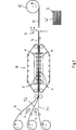
In
Des Weiteren wird auf das ein- oder mehrschichtige Trägermaterialband T1, T2, bei dem es sich vorzugsweise um ein Metallband oder ein Metall-Kunststoff-Verbundband handelt, ein thermoplastisches Stützmaterial S aufgebracht. Das thermoplastische Stützmaterial S liegt in dem dargestellten Ausführungsbeispiel ebenfalls als aufgewickeltes Band (Coil) vor. Mit
Die Bänder T1, T2, S werden mittels Umlenk- bzw. Führungsrollen zusammengeführt, in die Bandpresse P geleitet und dort miteinander zu einem bandförmigen Materialverbund W verpresst. Die Bandpresse P weist hierzu beheizte Rollen
Der in dem kontinuierlichen Bandlaufprozess erzeugte bandförmige Materialverbund W wird zu einem Coil C aufgewickelt oder mittels einer Schneideeinrichtung
Die Platinen oder Tafeln T3 werden beispielsweise durch Abwickeln und Ablängen eines entsprechenden Coils C2 erzeugt und anschließend mittels einer Transfervorrichtung
Ferner liegt es im Rahmen der vorliegenden Erfindung, anstelle der in
Des Weiteren umfasst das erfindungsgemäße Verfahren auch Ausführungsformen, bei denen die aufeinander gelegten Platinen, Tafeln T3, T4 bzw. Flächenstücke S' erhitzt und durch Aneinanderpressen in einer diskontinuierlich arbeitenden Presse zu einem flächigen Materialverbund (konsolidiertes Halbzeug) W' stoffschlüssig miteinander verbunden werden.Furthermore, the inventive method also includes embodiments in which the stacked boards, sheets T3, T4 or patches S 'are heated and joined together by pressing together in a discontinuous press to form a two-dimensional composite material (consolidated semi-finished) W'.
Die so, insbesondere gemäß
In den
Das Halbzeug W gemäß
Das in
Das in
Des Weiteren liegt es im Rahmen der vorliegenden Erfindung, das Halbzeug W' gemäß
Des Weiteren ist in
Das Flächenstück aus thermoplastischem Stützmaterial S bedeckt in dem in
Das in den
Das in den
Die in den
Die erfindungsgemäß hergestellten Halbzeuge W, W' werden in einem thermischen Umformprozess zu dreidimensional geformten Strukturbauteile B weiterverarbeitet. Während des Umformprozesses wird gleichzeitig eine Rippenstruktur RS in das thermoplastische Stützmaterial S eingeprägt. Hierzu wird das Halbzeug W, W' vor dem Zuführen in das Umformwerkzeug aufgeheizt, so dass sich das thermoplastische Stützmaterial S (und gegebenenfalls der faserverstärkte Thermoplast T2 oder T3) plastisch umformen und die Rippenstruktur RS erzeugen lässt (bzw. lassen).The semi-finished products W, W 'produced according to the invention are further processed in a thermal forming process into three-dimensionally shaped structural components B. During the forming process, a rib structure RS is impressed into the thermoplastic support material S at the same time. For this purpose, the semifinished product W, W 'is heated prior to feeding into the forming tool, so that the thermoplastic support material S (and optionally the fiber-reinforced thermoplastic T2 or T3) plastically reshape and can produce the rib structure RS (or leave).
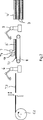
In
In
Die Platinen D werden zunächst auf eine für die nachfolgende Umformung des thermoplastischen Materials ausreichende Temperatur aufgeheizt. Dies wird beispielsweise mittels eines Durchlaufofens oder einer Heizstrahleinrichtung
Die in das thermoplastische Stützmaterial S eingeformte Rippenstruktur RS erhöht die Steifigkeit und Festigkeit des erfindungsgemäß hergestellten Strukturbauteils B. Die Rippenstruktur RS wird vorzugsweise zumindest partiell in Form einer wabenförmigen (
Prinzipiell, in den in der Zeichnung dargestellten Ausführungsbeispielen aber nicht gezeigt, liegt es auch im Rahmen der vorliegenden Erfindung, eine sogenannte „Funktionsintegration” im hergestellten Bauteil vorzusehen, d. h. dass Einleger, wie beispielsweise Schrauben, Muttern, Inserts etc., im Werkzeug positioniert und anschließend im formgebenden Prozess vom Stützmaterial aufgenommen („umspritzt”) werden, so dass ein Kraft- und Formschluss resultiert. Neben den genannten Rippenstrukturen können auch lokal beispielsweise Anschraubdome aus dem Stützmaterial geformt werden.In principle, but not shown in the embodiments shown in the drawing, it is also within the scope of the present invention to provide a so-called "functional integration" in the manufactured component, d. H. that depositors, such as screws, nuts, inserts, etc., positioned in the tool and then taken in the molding process of the support material ("encapsulated"), so that a positive and positive connection results. In addition to the aforementioned rib structures, it is also possible, for example, to locally form screw-on domes from the support material.
Die
Mit dem erfindungsgemäßen Verfahren können Strukturbauteile, die einer statischen und/oder dynamischen Belastung unterliegen, hergestellt werden, insbesondere Fahrzeugteile, zum Beispiel Seitenaufprallträger, Stoßfänger, Schweller, Verstärkungsbleche, Dachsäulen und auch Fahrzeugaußenhautteile, wie z. B. eine Türaußenhaut mit innenseitiger Verstärkungsstruktur und eine Motorhaube mit integrierter Innenstruktur.With the method according to the invention structural components which are subject to a static and / or dynamic load can be produced, in particular vehicle parts, for example side impact beams, bumpers, sills, reinforcing plates, roof pillars and also vehicle skin parts, such. B. an outside door skin with inside reinforcing structure and a hood with integrated internal structure.
ZITATE ENTHALTEN IN DER BESCHREIBUNG QUOTES INCLUDE IN THE DESCRIPTION
Diese Liste der vom Anmelder aufgeführten Dokumente wurde automatisiert erzeugt und ist ausschließlich zur besseren Information des Lesers aufgenommen. Die Liste ist nicht Bestandteil der deutschen Patent- bzw. Gebrauchsmusteranmeldung. Das DPMA übernimmt keinerlei Haftung für etwaige Fehler oder Auslassungen.This list of the documents listed by the applicant has been generated automatically and is included solely for the better information of the reader. The list is not part of the German patent or utility model application. The DPMA assumes no liability for any errors or omissions.
Zitierte PatentliteraturCited patent literature
- DE 102008058225 A1 [0003] DE 102008058225 A1 [0003]
- DE 102009042272 A1 [0004, 0004] DE 102009042272 A1 [0004, 0004]
Claims (14)
Priority Applications (9)
| Application Number | Priority Date | Filing Date | Title |
|---|---|---|---|
| DE102012111488.9A DE102012111488A1 (en) | 2012-11-27 | 2012-11-27 | Method for producing a structural component, in particular for a bodywork |
| PL13795470T PL2925499T3 (en) | 2012-11-27 | 2013-11-22 | Process for making a framework component for an autobody |
| CN201380062016.9A CN104812546B (en) | 2012-11-27 | 2013-11-22 | For manufacturing structural elements, particularly body structure component method |
| ES13795470.7T ES2614486T3 (en) | 2012-11-27 | 2013-11-22 | Procedure to manufacture a structural component for a body |
| EP13795470.7A EP2925499B1 (en) | 2012-11-27 | 2013-11-22 | Process for making a framework component for an autobody |
| US14/647,292 US10189190B2 (en) | 2012-11-27 | 2013-11-22 | Method for producing a structural component, particularly for a vehicle body |
| KR1020157016800A KR102178259B1 (en) | 2012-11-27 | 2013-11-22 | Method for producing a structural component, for a vehicle body |
| JP2015543440A JP6416771B2 (en) | 2012-11-27 | 2013-11-22 | Manufacturing method for structural parts especially for vehicle bodies |
| PCT/EP2013/074477 WO2014082929A1 (en) | 2012-11-27 | 2013-11-22 | Method for producing a structural component, particularly for a vehicle body |
Applications Claiming Priority (1)
| Application Number | Priority Date | Filing Date | Title |
|---|---|---|---|
| DE102012111488.9A DE102012111488A1 (en) | 2012-11-27 | 2012-11-27 | Method for producing a structural component, in particular for a bodywork |
Publications (1)
| Publication Number | Publication Date |
|---|---|
| DE102012111488A1 true DE102012111488A1 (en) | 2014-05-28 |
Family
ID=49641744
Family Applications (1)
| Application Number | Title | Priority Date | Filing Date |
|---|---|---|---|
| DE102012111488.9A Ceased DE102012111488A1 (en) | 2012-11-27 | 2012-11-27 | Method for producing a structural component, in particular for a bodywork |
Country Status (9)
| Country | Link |
|---|---|
| US (1) | US10189190B2 (en) |
| EP (1) | EP2925499B1 (en) |
| JP (1) | JP6416771B2 (en) |
| KR (1) | KR102178259B1 (en) |
| CN (1) | CN104812546B (en) |
| DE (1) | DE102012111488A1 (en) |
| ES (1) | ES2614486T3 (en) |
| PL (1) | PL2925499T3 (en) |
| WO (1) | WO2014082929A1 (en) |
Cited By (14)
| Publication number | Priority date | Publication date | Assignee | Title |
|---|---|---|---|---|
| DE102013222425A1 (en) * | 2013-11-05 | 2015-05-07 | Bayerische Motoren Werke Aktiengesellschaft | Manufacturing process CFRP steel hybrid components and CFRP hybrid component / tool |
| DE102014107898A1 (en) * | 2014-06-04 | 2015-12-17 | Thyssenkrupp Ag | Process and apparatus for composite production with direct laminar column heating |
| EP3078474A1 (en) * | 2015-04-07 | 2016-10-12 | Faurecia Exteriors GmbH | Method for producing an element made of composite material and element produced by such a method |
| DE102015109863A1 (en) * | 2015-06-19 | 2016-12-22 | Dr. Ing. H.C. F. Porsche Aktiengesellschaft | Vehicle component and method |
| DE102016109728A1 (en) * | 2016-05-25 | 2017-11-30 | Boge Elastmetall Gmbh | Method for producing a component from a fiber composite material |
| DE102017201834A1 (en) | 2017-02-06 | 2018-08-09 | Thyssenkrupp Ag | Semi-finished product with different properties |
| DE102017218475A1 (en) * | 2017-10-16 | 2019-04-18 | Bayerische Motoren Werke Aktiengesellschaft | Method for producing a body component with locally different hardness properties |
| DE102018204353A1 (en) | 2018-03-21 | 2019-09-26 | Audi Ag | Adjusting device with a plate-shaped component |
| DE102018207211A1 (en) * | 2018-05-09 | 2019-11-14 | Thyssenkrupp Ag | Hybrid steel-plastic semi-finished product with shielding properties |
| DE102018207205A1 (en) * | 2018-05-09 | 2019-11-14 | Thyssenkrupp Ag | Hybrid steel-plastic housing for power electronics |
| DE102018130879A1 (en) * | 2018-12-04 | 2020-06-04 | Bayerische Motoren Werke Aktiengesellschaft | Wheel house cover for a vehicle and vehicle with a wheel house cover |
| DE102020126841A1 (en) | 2020-10-13 | 2022-04-14 | Universität Paderborn, Körperschaft des öffentlichen Rechts | Process for the production of a hybrid component made of metal and fiber-reinforced plastic by impact extrusion |
| DE102021130445B3 (en) | 2021-11-22 | 2023-02-02 | Audi Aktiengesellschaft | Crash management system for a motor vehicle with a bumper element in sandwich construction, manufacturing method for this and motor vehicle |
| US11911933B2 (en) * | 2015-03-30 | 2024-02-27 | Mitsubishi Chemical Corporation | Molded body and manufacturing method therefor |
Families Citing this family (17)
| Publication number | Priority date | Publication date | Assignee | Title |
|---|---|---|---|---|
| JP6459557B2 (en) * | 2015-01-27 | 2019-01-30 | 日本精工株式会社 | Manufacturing method of housing member and cover member of gear box of electric power steering apparatus |
| CN106218366B (en) * | 2016-08-25 | 2018-09-07 | 温州市聚达信息科技有限公司 | Wheeled transport tool |
| KR20190095318A (en) | 2016-12-28 | 2019-08-14 | 닛테츠 케미컬 앤드 머티리얼 가부시키가이샤 | Metal-Fiber Reinforced Resin Material Composites, Method of Making the Same, and Adhesive Sheet |
| EP3595853A4 (en) | 2017-03-16 | 2020-12-23 | Guerrilla Industries LLC | Composite structures and methods of forming composite structures |
| TW201903013A (en) | 2017-03-31 | 2019-01-16 | 日商新日鐵住金化學股份有限公司 | Metal-fiber reinforced resin material composite and method of producing the same |
| JP7215163B2 (en) | 2017-12-28 | 2023-01-31 | 日本製鉄株式会社 | Metal-fiber reinforced resin material composite |
| JP7295376B2 (en) | 2017-12-28 | 2023-06-21 | 日本製鉄株式会社 | METAL-FIBER REINFORCED RESIN MATERIAL COMPOSITE AND PRODUCTION METHOD THEREOF |
| US11168767B2 (en) * | 2018-10-23 | 2021-11-09 | Gates Corporation | Tensioner |
| JP7135760B2 (en) * | 2018-11-16 | 2022-09-13 | トヨタ自動車株式会社 | Welding electrode processing device and welding electrode processing method |
| DE102019204460A1 (en) * | 2019-03-29 | 2020-10-01 | Fraunhofer-Gesellschaft zur Förderung der angewandten Forschung e.V. | Method for producing a sandwich composite component with a pressed two- or three-dimensional shape and such a sandwich composite component |
| JP7376295B2 (en) * | 2019-09-25 | 2023-11-08 | 株式会社Subaru | Fiber-reinforced resin composite material and method for producing fiber-reinforced resin composite material |
| DE102020203523A1 (en) | 2020-03-19 | 2021-09-23 | Volkswagen Aktiengesellschaft | Process for the production of a component by local thermoforming |
| CN111958682A (en) * | 2020-07-29 | 2020-11-20 | 北京机科国创轻量化科学研究院有限公司 | Carbon fiber fabric pre-forming and cutting device and processing method |
| US11945139B2 (en) * | 2020-08-14 | 2024-04-02 | Arris Composites Inc. | Method for composite truss manufacturing |
| CN112139356A (en) * | 2020-09-18 | 2020-12-29 | 苏州邦得新材料科技有限公司 | Manufacturing method of steel metal printing woven plate and steel metal printing woven plate |
| WO2022192355A1 (en) | 2021-03-09 | 2022-09-15 | Guerrilla Industries LLC | Composite structures and methods of forming composite structures |
| DE102021109155A1 (en) * | 2021-04-13 | 2022-10-13 | HELLA GmbH & Co. KGaA | Automotive component having a metal-plastic composite body |
Citations (4)
| Publication number | Priority date | Publication date | Assignee | Title |
|---|---|---|---|---|
| WO2006037852A1 (en) * | 2004-10-01 | 2006-04-13 | Avantone Oy | A product comprising a protected microstructured area, and a method and a device for producing the same |
| DE102008058225A1 (en) | 2008-11-19 | 2010-07-08 | Lanxess Deutschland Gmbh | Lightweight component in hybrid construction |
| DE102009023653A1 (en) * | 2009-05-27 | 2010-12-02 | Göbel, Christian | Method for manufacturing molded parts and flat plate material made of paper plastic composite by compressing into a tool under heat and pressure, where the tool is permanently heated or temporally heated for a respective holding time |
| DE102009042272A1 (en) | 2009-09-22 | 2011-03-31 | Dr. Ing. H.C. F. Porsche Aktiengesellschaft | Lightweight component e.g. A-column, for use in motor vehicle, has reinforcement structure made of plastic, and metal sheet connected with reinforcement layer made of plastic in material-fit manner |
Family Cites Families (18)
| Publication number | Priority date | Publication date | Assignee | Title |
|---|---|---|---|---|
| SE404503B (en) * | 1973-01-16 | 1978-10-09 | Hercules Inc | PROCEDURE FOR TRANSFORMING A THERMOPLASTIC FOIL TO A WIRE PRODUCT |
| JPS55133762A (en) * | 1979-04-06 | 1980-10-17 | Asahi Chem Ind Co Ltd | Manufacture of separator with horizontal rib |
| JPS56144956A (en) | 1980-04-14 | 1981-11-11 | Toyo Kogyo Co | Composite lid structure for automobile |
| JPS58181250U (en) * | 1982-05-26 | 1983-12-03 | ダイハツ工業株式会社 | Seat frame for car “A” |
| JPS61816A (en) * | 1984-06-13 | 1986-01-06 | Mitsubishi Electric Corp | Controller of unmanned truck |
| JPH04259515A (en) | 1991-02-13 | 1992-09-16 | Mitsui Toatsu Chem Inc | Structure |
| JP3273807B2 (en) * | 1992-05-06 | 2002-04-15 | マツダ株式会社 | Press molding method of liquid crystal resin composite |
| JPH0639861A (en) | 1992-07-23 | 1994-02-15 | Nishikawa Kasei Co Ltd | Skin integrated molded product and production thereof |
| JPH0827281A (en) | 1994-07-20 | 1996-01-30 | Kuraray Co Ltd | Glass fiber-reinforced composite material |
| FR2749535B1 (en) | 1996-06-07 | 1998-08-28 | Manducher Sa | PART BASED ON THERMOPLASTIC MATERIAL FOR A MOTOR VEHICLE AND METHOD FOR MANUFACTURING THE SAME |
| EP1336469A1 (en) | 2002-02-19 | 2003-08-20 | Alenia Aeronautica S.P.A. | Methods of manufacturing a stiffening element for an aircraft skin panel and a skin panel provided with the stiffening element |
| AT501702B1 (en) | 2005-03-17 | 2012-02-15 | Constantia Teich Gmbh | COMPOSITE MATERIAL FOR CLOSURE ELEMENTS, METHOD FOR THE PRODUCTION THEREOF AND THE USE THEREOF |
| JP2008194887A (en) * | 2007-02-09 | 2008-08-28 | Nippon Steel Corp | Manufacturing method of vibration damping structure for vehicle |
| JP5350918B2 (en) * | 2009-07-08 | 2013-11-27 | 本田技研工業株式会社 | Laminated structure, laminated structure manufacturing method, and laminated structure manufacturing apparatus |
| DE102010054195A1 (en) * | 2010-12-11 | 2012-06-14 | Daimler Ag | Method for manufacturing composite component for motor vehicle e.g. passenger car, involves providing semi-finished product with plastic by injection mold tools |
| JP5712943B2 (en) | 2011-03-17 | 2015-05-07 | 東レ株式会社 | Method for producing metal composite |
| JP5740199B2 (en) * | 2011-03-30 | 2015-06-24 | 積水化学工業株式会社 | Method for producing composite molded body |
| DE102011100396A1 (en) | 2011-05-04 | 2012-11-08 | Daimler Ag | Producing component for motor vehicle, comprises partially heating base member made of plastic and fibers by heating device, providing additional plastic by tool, conveying base member by conveyor into operative region of heating device |
-
2012
- 2012-11-27 DE DE102012111488.9A patent/DE102012111488A1/en not_active Ceased
-
2013
- 2013-11-22 ES ES13795470.7T patent/ES2614486T3/en active Active
- 2013-11-22 US US14/647,292 patent/US10189190B2/en not_active Expired - Fee Related
- 2013-11-22 CN CN201380062016.9A patent/CN104812546B/en not_active Expired - Fee Related
- 2013-11-22 EP EP13795470.7A patent/EP2925499B1/en active Active
- 2013-11-22 JP JP2015543440A patent/JP6416771B2/en not_active Expired - Fee Related
- 2013-11-22 WO PCT/EP2013/074477 patent/WO2014082929A1/en active Application Filing
- 2013-11-22 KR KR1020157016800A patent/KR102178259B1/en active IP Right Grant
- 2013-11-22 PL PL13795470T patent/PL2925499T3/en unknown
Patent Citations (4)
| Publication number | Priority date | Publication date | Assignee | Title |
|---|---|---|---|---|
| WO2006037852A1 (en) * | 2004-10-01 | 2006-04-13 | Avantone Oy | A product comprising a protected microstructured area, and a method and a device for producing the same |
| DE102008058225A1 (en) | 2008-11-19 | 2010-07-08 | Lanxess Deutschland Gmbh | Lightweight component in hybrid construction |
| DE102009023653A1 (en) * | 2009-05-27 | 2010-12-02 | Göbel, Christian | Method for manufacturing molded parts and flat plate material made of paper plastic composite by compressing into a tool under heat and pressure, where the tool is permanently heated or temporally heated for a respective holding time |
| DE102009042272A1 (en) | 2009-09-22 | 2011-03-31 | Dr. Ing. H.C. F. Porsche Aktiengesellschaft | Lightweight component e.g. A-column, for use in motor vehicle, has reinforcement structure made of plastic, and metal sheet connected with reinforcement layer made of plastic in material-fit manner |
Cited By (18)
| Publication number | Priority date | Publication date | Assignee | Title |
|---|---|---|---|---|
| DE102013222425A1 (en) * | 2013-11-05 | 2015-05-07 | Bayerische Motoren Werke Aktiengesellschaft | Manufacturing process CFRP steel hybrid components and CFRP hybrid component / tool |
| DE102014107898A1 (en) * | 2014-06-04 | 2015-12-17 | Thyssenkrupp Ag | Process and apparatus for composite production with direct laminar column heating |
| US11911933B2 (en) * | 2015-03-30 | 2024-02-27 | Mitsubishi Chemical Corporation | Molded body and manufacturing method therefor |
| EP3078474A1 (en) * | 2015-04-07 | 2016-10-12 | Faurecia Exteriors GmbH | Method for producing an element made of composite material and element produced by such a method |
| WO2016162242A1 (en) * | 2015-04-07 | 2016-10-13 | Faurecia Exteriors Gmbh | Method for producing an element made of composite material and element produced by such a method |
| DE102015109863A1 (en) * | 2015-06-19 | 2016-12-22 | Dr. Ing. H.C. F. Porsche Aktiengesellschaft | Vehicle component and method |
| US10730248B2 (en) | 2016-05-25 | 2020-08-04 | Boge Elastmetall Gmbh | Method for producing a component from a fiber-composite material |
| DE102016109728A1 (en) * | 2016-05-25 | 2017-11-30 | Boge Elastmetall Gmbh | Method for producing a component from a fiber composite material |
| DE102017201834A1 (en) | 2017-02-06 | 2018-08-09 | Thyssenkrupp Ag | Semi-finished product with different properties |
| DE102017218475A1 (en) * | 2017-10-16 | 2019-04-18 | Bayerische Motoren Werke Aktiengesellschaft | Method for producing a body component with locally different hardness properties |
| DE102018204353A1 (en) | 2018-03-21 | 2019-09-26 | Audi Ag | Adjusting device with a plate-shaped component |
| DE102018204353B4 (en) | 2018-03-21 | 2021-09-30 | Audi Ag | Adjusting device with a plate-shaped component |
| DE102018207211A1 (en) * | 2018-05-09 | 2019-11-14 | Thyssenkrupp Ag | Hybrid steel-plastic semi-finished product with shielding properties |
| DE102018207205A1 (en) * | 2018-05-09 | 2019-11-14 | Thyssenkrupp Ag | Hybrid steel-plastic housing for power electronics |
| DE102018130879A1 (en) * | 2018-12-04 | 2020-06-04 | Bayerische Motoren Werke Aktiengesellschaft | Wheel house cover for a vehicle and vehicle with a wheel house cover |
| DE102020126841A1 (en) | 2020-10-13 | 2022-04-14 | Universität Paderborn, Körperschaft des öffentlichen Rechts | Process for the production of a hybrid component made of metal and fiber-reinforced plastic by impact extrusion |
| DE102021130445B3 (en) | 2021-11-22 | 2023-02-02 | Audi Aktiengesellschaft | Crash management system for a motor vehicle with a bumper element in sandwich construction, manufacturing method for this and motor vehicle |
| WO2023088637A1 (en) | 2021-11-22 | 2023-05-25 | Audi Ag | Crash management system for a motor vehicle having bumper element with a sandwich structure, production methods therefor and motor vehicle |
Also Published As
| Publication number | Publication date |
|---|---|
| CN104812546A (en) | 2015-07-29 |
| ES2614486T3 (en) | 2017-05-31 |
| US20150298368A1 (en) | 2015-10-22 |
| WO2014082929A1 (en) | 2014-06-05 |
| JP6416771B2 (en) | 2018-10-31 |
| JP2015536850A (en) | 2015-12-24 |
| KR20150089051A (en) | 2015-08-04 |
| CN104812546B (en) | 2018-05-15 |
| EP2925499B1 (en) | 2016-11-09 |
| EP2925499A1 (en) | 2015-10-07 |
| US10189190B2 (en) | 2019-01-29 |
| KR102178259B1 (en) | 2020-11-12 |
| PL2925499T3 (en) | 2017-07-31 |
Similar Documents
| Publication | Publication Date | Title |
|---|---|---|
| EP2925499B1 (en) | Process for making a framework component for an autobody | |
| EP3041674B2 (en) | Semi-finished product and method for producing a three-dimensionally shaped hybrid component in the metal/plastics composite, and the use of such a semi-finished product | |
| DE102011118980B4 (en) | Method for producing an outer module with an outer panel for a modular housing component | |
| EP3074299A1 (en) | Method for the production of an exterior trim panel for a movable body part and a corresponding exterior trim panel with reinforcement by back injecting fibre-reinforced material | |
| DE102008034207A1 (en) | Method for producing a sandwich component from cold strip | |
| WO2016020148A1 (en) | Method for producing hot-formed components | |
| EP1362744B1 (en) | Building element of synthetic material, in particular for an automobile, and process for manufacturing it | |
| DE102013021672A1 (en) | Process for producing a hybrid component | |
| DE102009046413A1 (en) | Solidifying an adhesive during joining of components, useful in automotive industry, comprises forming first and second components as an overlapping joint with each other, and solidifying circulating adhesive by introducing heat at joint | |
| DE102011007937B4 (en) | Method for producing a structural component of a motor vehicle body | |
| WO2016091459A1 (en) | Composite component and method for the production and use thereof | |
| EP3359377B1 (en) | Method and system for continuously producing composite strips or composite sheets | |
| WO2018077710A1 (en) | Multi-layered structural component, method for production thereof, and uses thereof | |
| DE4312555A1 (en) | Process for producing multilayered workpieces and workpiece based on this process | |
| DE102014224463A1 (en) | Process for producing a multilayer molded body | |
| DE102013102056B4 (en) | Process for producing a sound-absorbing thermoplastic heavy layer semi-finished product and device for carrying out the process | |
| DE102019204460A1 (en) | Method for producing a sandwich composite component with a pressed two- or three-dimensional shape and such a sandwich composite component | |
| DE102019124642A1 (en) | Trim component for a motor vehicle and method for producing a trim component and sandwich material for a trim component | |
| DE102013018655A1 (en) | Method for producing a cladding component and cladding component | |
| DE102009006367A1 (en) | A method for producing a Umbugs on an edge of a plastic component and apparatus for performing this method | |
| WO2005005145A2 (en) | Method for the production of a laminate, device for carrying out the method and corresponding laminate | |
| DE102014017689A1 (en) | Method for producing a composite material with weldable flange | |
| DE102021109791A1 (en) | Method for producing a panel-like sandwich component and load-bearing panel-like sandwich component produced therewith | |
| DE102014206447A1 (en) | Process for producing a fiber-reinforced plastic molding | |
| DE102012104188A1 (en) | Sound-absorbing thermoplastic heavy layer semi-finished material i.e. dimensional heavy layer shell, for front wall part of passenger car, has connection points integrally connected to each other at top surfaces in overlapping regions |
Legal Events
| Date | Code | Title | Description |
|---|---|---|---|
| R012 | Request for examination validly filed | ||
| R002 | Refusal decision in examination/registration proceedings | ||
| R003 | Refusal decision now final |