DE102010018552B4 - Seal assembly and link of a chain with the seal assembly - Google Patents
Seal assembly and link of a chain with the seal assembly Download PDFInfo
- Publication number
- DE102010018552B4 DE102010018552B4 DE102010018552.3A DE102010018552A DE102010018552B4 DE 102010018552 B4 DE102010018552 B4 DE 102010018552B4 DE 102010018552 A DE102010018552 A DE 102010018552A DE 102010018552 B4 DE102010018552 B4 DE 102010018552B4
- Authority
- DE
- Germany
- Prior art keywords
- sealing
- ring
- chain
- support ring
- contact surface
- Prior art date
- Legal status (The legal status is an assumption and is not a legal conclusion. Google has not performed a legal analysis and makes no representation as to the accuracy of the status listed.)
- Active
Links
Images

Classifications
-
- B—PERFORMING OPERATIONS; TRANSPORTING
- B62—LAND VEHICLES FOR TRAVELLING OTHERWISE THAN ON RAILS
- B62D—MOTOR VEHICLES; TRAILERS
- B62D55/00—Endless track vehicles
- B62D55/08—Endless track units; Parts thereof
- B62D55/088—Endless track units; Parts thereof with means to exclude or remove foreign matter, e.g. sealing means, self-cleaning track links or sprockets, deflector plates or scrapers
- B62D55/0887—Track-articulation sealings against dust, water, mud or the like
-
- B—PERFORMING OPERATIONS; TRANSPORTING
- B62—LAND VEHICLES FOR TRAVELLING OTHERWISE THAN ON RAILS
- B62D—MOTOR VEHICLES; TRAILERS
- B62D55/00—Endless track vehicles
-
- B—PERFORMING OPERATIONS; TRANSPORTING
- B62—LAND VEHICLES FOR TRAVELLING OTHERWISE THAN ON RAILS
- B62D—MOTOR VEHICLES; TRAILERS
- B62D55/00—Endless track vehicles
- B62D55/08—Endless track units; Parts thereof
-
- F—MECHANICAL ENGINEERING; LIGHTING; HEATING; WEAPONS; BLASTING
- F16—ENGINEERING ELEMENTS AND UNITS; GENERAL MEASURES FOR PRODUCING AND MAINTAINING EFFECTIVE FUNCTIONING OF MACHINES OR INSTALLATIONS; THERMAL INSULATION IN GENERAL
- F16J—PISTONS; CYLINDERS; SEALINGS
- F16J15/00—Sealings
- F16J15/16—Sealings between relatively-moving surfaces
- F16J15/34—Sealings between relatively-moving surfaces with slip-ring pressed against a more or less radial face on one member
- F16J15/3436—Pressing means
- F16J15/344—Pressing means the pressing force being applied by means of an elastic ring supporting the slip-ring
Landscapes
- Engineering & Computer Science (AREA)
- Mechanical Engineering (AREA)
- Chemical & Material Sciences (AREA)
- Combustion & Propulsion (AREA)
- Transportation (AREA)
- General Engineering & Computer Science (AREA)
- Sealing With Elastic Sealing Lips (AREA)
- Sealing Devices (AREA)
Abstract
Dichtungsanordnung zum Dichten zwischen zwei gegeneinander beweglichen Teilen einer Kette, aufweisend einen Elastikring (4; 104), der eine radial umlaufende Dichtlippe (5) zum festen und dichtenden Anliegen an einem ersten Teil der Kette aufweist und aufweisend einen Dichtring (11; 111) mit einer Dichtkante (13; 113) und einen Stützring (7; 107), wobei der Stützring gegenüber dem Dichtring verdrehbar ist und eine Anlauffläche (25; 125) aufweist, an der die Dichtkante dichtend anliegt, dadurch gekennzeichnet, dass der Stützring radial an dem Dichtring anliegt.Sealing arrangement for sealing between two mutually movable parts of a chain, having an elastic ring (4; 104) which has a radially circumferential sealing lip (5) for firm and sealing contact with a first part of the chain and having a sealing ring (11; 111). a sealing edge (13; 113) and a support ring (7; 107), the support ring being rotatable relative to the sealing ring and having a contact surface (25; 125) against which the sealing edge bears in a sealing manner, characterized in that the support ring is radially attached to the sealing ring.
Description
Die Erfindung betrifft eine Dichtungsanordnung zum Dichten zwischen zwei gegeneinander beweglichen Teilen einer Kette und ein Gelenk einer Kette mit der Dichtungsanordnung.The invention relates to a sealing arrangement for sealing between two mutually movable parts of a chain and a joint of a chain with the sealing arrangement.
Bei Ketten insbesondere von Kettenfahrzeugen sind üblicherweise die Glieder der Kette über Drehzapfengelenke miteinander verbunden. Dabei umfasst ein derartiges Drehzapfengelenk einen Bolzen und eine Hülse, die drehbar über den Bolzen aufgeschoben ist, wobei an den Enden des Bolzens und der Hülse jeweils Glieder der Kette aufgepresst sind. Die Drehlageroberflächen zwischen dem Bolzen und der Hülse werden durch eine Ölkammer im Bolzen geschmiert, wobei der Ölraum zwischen Bolzen und Hülse durch zwei Dichtelemente abgedichtet wird, die gegen die Stirnflächen der Hülse drückende Dichtlippen umfassen.In the case of chains, in particular of tracked vehicles, the links of the chain are usually connected to one another via pivot joints. Such a pivot joint comprises a bolt and a sleeve which is rotatably pushed over the bolt, links of the chain being pressed onto the ends of the bolt and the sleeve. The pivot bearing surfaces between the pin and the sleeve are lubricated by an oil chamber in the pin, the oil space between the pin and sleeve being sealed by two sealing elements comprising sealing lips pressing against the end faces of the sleeve.
In der Druschrift
Beispielsweise aus der
Aus der
Aus der
Es ist Aufgabe der Erfindung, eine Dichtungsanordnung zum Dichten zwischen einem ersten Teil einer Kette und einem zweiten, gegenüber dem ersten wenigstens verschwenkbaren Teil der Kette zu schaffen, die insbesondere eine lange Lebensdauer aufweist, sowie ein entsprechendes Gelenk einer Kette anzugeben.The object of the invention is to create a sealing arrangement for sealing between a first part of a chain and a second part of the chain that can be at least pivoted relative to the first part, which has a particularly long service life, and to specify a corresponding joint of a chain.
Die Aufgabe wird durch den Gegenstand des Anspruchs 1 bzw. 10 gelöst. Vorteilhafte Ausgestaltungen sind Gegenstand der Unteransprüche.The object is solved by the subject matter of claims 1 and 10, respectively. Advantageous configurations are the subject matter of the dependent claims.
Gemäß Patentanspruch 1 wird eine Dichtungsanordnung zum Dichten zwischen zwei gegeneinander beweglichen Teilen einer Kette angegeben, aufweisend einen Elastikring, der eine radial umlaufende Dichtlippe zum festen und dichtenden Anliegen an einem ersten Teil der Kette aufweist und aufweisend einen Stützring und einen Dichtring mit einer Dichtkante. Der Stützring ist gegenüber dem Dichtring verdrehbar und weist eine Anlauffläche auf, an der die Dichtkante dichtend anliegt. Ferner liegt der Stützring radial an dem Dichtring an.According to claim 1, a sealing arrangement for sealing between two mutually movable parts of a chain is specified, having an elastic ring which has a radially circumferential sealing lip for firm and sealing contact with a first part of the chain and having a support ring and a sealing ring with a sealing edge. The support ring can be rotated relative to the sealing ring and has a contact surface against which the sealing edge rests in a sealing manner. Furthermore, the support ring bears radially against the sealing ring.
Bei bekannten Ausführungen von Dichtungsanordnungen für Kettengelenke liegt die Dichtkante an einer Hülse des Kettengelenks an. Die Dichtkante ist also bezüglich der Dichtungsanordnung axial oder radial nach außen gerichtet. Die Hülse des Kettengelenks weist für die Dichtkante entsprechend eine Anlauffläche auf. Damit die Anlauffläche in Zusammenwirkung mit der Dichtkante eine möglichst hohe Lebensdauer bei gleichzeitig hoher Dichtwirkung erreicht muss die Anlauffläche der Hülse im Allgemeinen geläppt und zusätzlich gehärtet sein. Dies erfordert bereits beim Herstellen der Bauteile der Kettengelenke einen vergleichsweise hohen Fertigungsaufwand.In known designs of sealing arrangements for chain joints, the sealing edge is in contact with a sleeve of the chain joint. The sealing edge is therefore directed axially or radially outward with respect to the sealing arrangement. The sleeve of the chain link has a contact surface for the sealing edge. In order for the contact surface in cooperation with the sealing edge to achieve the longest possible service life with a high sealing effect at the same time, the contact surface of the sleeve must generally be lapped and additionally hardened. This already requires the manufacture of the components Chain joints a comparatively high production cost.
Im Unterschied dazu ist die Anlauffläche für die Dichtkante bei der erfindungsgemäßen Dichtungsanordnung am Stützring selbst ausgeführt. Die dynamische Dichtfunktion der Dichtungsanordnung ist folglich durch die über die Anlauffläche gleitende Dichtkante des Dichtrings und somit ohne Einbeziehung nicht zur Dichtungsanordnung selbst gehörender Bauteile verwirklicht. Mit der erfindungsgemäßen Dichtungsanordnung ist es möglich, die beweglichen Teile der Kette im Vergleich zu bekannten Ausführungsbeispielen deutlich einfacher auszuführen. Insbesondere ist es nicht mehr erforderlich, eine Anlauffläche für die Dichtkante an einem nicht zur Dichtung gehörenden Bauteil vorzusehen, die zusätzlich mit aufwändigen Methoden verschleißarm gemacht werden muss.In contrast to this, the contact surface for the sealing edge in the sealing arrangement according to the invention is designed on the support ring itself. The dynamic sealing function of the sealing arrangement is consequently realized by the sealing edge of the sealing ring sliding over the contact surface and thus without including components that do not belong to the sealing arrangement itself. With the sealing arrangement according to the invention, it is possible to design the moving parts of the chain in a significantly simpler manner in comparison to known exemplary embodiments. In particular, it is no longer necessary to provide a contact surface for the sealing edge on a component that does not belong to the seal, which must also be made wear-resistant using complex methods.
In einer bevorzugten Ausführungsform besteht der Stützring aus einem metallischen Material. Der Stützring kann insbesondere aus einem derart harten Metall oder einer entsprechenden Legierung bestehen, dass die Anlauffläche keiner zusätzlichen Härtung bedarf. Insofern lässt sich mit vergleichsweise einfachen Mitteln eine verschleißarme Anlauffläche herstellen, wobei gleichzeitig eine hohe Lebensdauer bei gleichzeitig guter Dichtwirkung der Dichtkante gewährleistet ist.In a preferred embodiment, the support ring consists of a metallic material. In particular, the support ring can consist of such a hard metal or a corresponding alloy that the contact surface does not require any additional hardening. In this respect, a low-wear contact surface can be produced with comparatively simple means, with a long service life and good sealing effect of the sealing edge being ensured at the same time.
In einer weiteren bevorzugten Ausführungsform ist die Anlauffläche gehärtet und/oder geläppt. In dieser Ausführungsform lässt sich der Stützring auch aus einem Material herstellen, das im Vergleich zu harten metallischen Materialien einen erhöhten Verschleiß aufweist. Durch Läppen und/oder Härten der Anlauffläche wird der Verschleiß gezielt in diesem Bereich reduziert und so eine lange Lebensdauer der Dichtungsanordnung gewährleistet. Vorteilhaft hierbei ist jedoch, dass die Qualität der Anlauffläche auf die jeweilige Dichtkante gut abstimmbar ist. Im Allgemeinen wird nämlich die Dichtungsanordnung als komplette Baueinheit gefertigt und erst beim Zusammenbau der gesamten Kette mit den beweglichen Elementen der Kette zusammengebracht. Bei bekannten Ausführungsformen von Dichtungsanordnungen wurde somit die eigentliche dynamische Dichtfunktion durch Dichtkante und Anlauffläche an einem Element der Kette durch zwei verschiedene Herstellungsprozesse und erst nach dem Montageprozess der Kette vervollständigt. Bei der erfindungsgemäßen Dichtungsanordnung lässt sich dies komplett in einer Baueinheit, nämlich der Dichtungsanordnung selbst, gewährleisten.In a further preferred embodiment, the contact surface is hardened and/or lapped. In this embodiment, the support ring can also be made from a material that exhibits increased wear compared to hard metallic materials. By lapping and/or hardening the contact surface, wear is specifically reduced in this area and a long service life of the sealing arrangement is thus ensured. However, the advantage here is that the quality of the contact surface can be easily adjusted to the respective sealing edge. In general, namely, the sealing arrangement is manufactured as a complete structural unit and is brought together with the moving elements of the chain only when the entire chain is assembled. In known embodiments of sealing arrangements, the actual dynamic sealing function was thus completed by the sealing edge and contact surface on an element of the chain by two different manufacturing processes and only after the assembly process of the chain. In the case of the sealing arrangement according to the invention, this can be ensured completely in one structural unit, namely the sealing arrangement itself.
In einer bevorzugten Ausführungsform der Erfindung weist der Dichtring wenigstens eine Nut auf, durch die Öl zur Dichtkante führbar ist. Zur Gewährleistung einer guten Dichtfunktion ist die Dichtkante zu schmieren. Dies vermindert zudem den Abrieb auf der Anlauffläche des Stützrings. Insofern ist eine Sicherstellung der Ölzuführung vorteilhaft für die Lebensdauer der Dichtungsanordnung. Durch eine Nut im Dichtungsring lässt sich eine Verbindung zum nach außen abzudichtenden Ölraum herstellen, sodass die Dichtkante und die Anlauffläche entsprechend mit Öl geschmiert werden können.In a preferred embodiment of the invention, the sealing ring has at least one groove through which oil can be guided to the sealing edge. To ensure a good sealing function, the sealing edge must be lubricated. This also reduces abrasion on the contact surface of the support ring. In this respect, ensuring the oil supply is advantageous for the service life of the sealing arrangement. A groove in the sealing ring creates a connection to the oil chamber to be sealed to the outside, so that the sealing edge and the contact surface can be lubricated with oil accordingly.
In einer vorteilhaften Ausgestaltung der Erfindung ist der Stützring fest mit dem Elastikring verbunden, wobei der Stützring zwischen dem Elastikring und dem Dichtring angeordnet ist. In dieser Ausführungsform ist die Dichtkante des Dichtrings folglich axial oder radial in Richtung des Elastikrings ausgeführt, sodass sie auf der Anlauffläche des dazwischen liegenden Stützrings ihre Dichtfunktion ausüben kann.In an advantageous embodiment of the invention, the support ring is firmly connected to the elastic ring, with the support ring being arranged between the elastic ring and the sealing ring. In this embodiment, the sealing edge of the sealing ring is consequently designed axially or radially in the direction of the elastic ring, so that it can perform its sealing function on the contact surface of the support ring lying in between.
In einer vorteilhaften Ausgestaltung der Erfindung weist der Dichtring eine Dichtfläche zum festen und dichtenden Anliegen am zweiten Teil der Kette auf. Somit lässt sich der Dichtring verdrehsicher mit dem zweiten Teil der Kette verbinden. Folglich ist die dynamische Dichtfunktion auf die an der Anlauffläche des Stützrings gleitende Dichtkante des Dichtrings reduziert.In an advantageous embodiment of the invention, the sealing ring has a sealing surface for firm and sealing contact with the second part of the chain. The sealing ring can thus be connected to the second part of the chain in a twist-proof manner. Consequently, the dynamic sealing function is reduced to the sealing edge of the sealing ring sliding on the contact surface of the support ring.
In einer alternativen Ausführungsform der Erfindung ist der Dichtring fest mit dem Elastikring verbunden und zwischen dem Elastikring und dem Stützring angeordnet. In diesem Ausführungsbeispiel weist bevorzugt der Stützring eine Dichtfläche zum festen und dichtenden Anliegen am zweiten Teil der Kette auf. In beiden Ausführungsformen ist die Dichtfläche bevorzugt mit einem Material belegt, das weicher als das Material des Dichtrings bzw. des Stützrings ist. Dadurch lässt sich eine gute Haltefunktion am zweiten Teil der Kette sicherstellen.In an alternative embodiment of the invention, the sealing ring is firmly connected to the elastic ring and is arranged between the elastic ring and the support ring. In this exemplary embodiment, the support ring preferably has a sealing surface for firm and sealing contact with the second part of the chain. In both embodiments, the sealing surface is preferably covered with a material that is softer than the material of the sealing ring or the support ring. This ensures a good holding function on the second part of the chain.
Weitere Vorteile und Ausgestaltungen der Erfindung ergeben sich aus dem nachfolgend beschriebenen Ausführungsbeispiel anhand der beigefügten Figuren. Dabei zeigen die
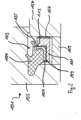
In der
Die Dichtung 3 umfasst einen Elastikring 4, der beispielsweise aus einem Elastomer besteht. Der Elastikring 4 weist eine Dichtlippe 5 auf, die zum Anliegen an einer Dichtfläche oder Gegenfläche des äußeren Kettengliedes 52 ausgebildet ist. Der Elastikring 4 ist radial umlaufend ausgeführt und auf seiner radial nach innen gerichteten Seite mit einem Dichtring 11 fest verbunden. Zwischen dem Elastikring 4 und dem Dichtring 11 ist eine Kontaktfläche 15 ausgebildet. Die Dichtung 3 umfasst weiter einen Stützring 7, der eine im Wesentlichen L-förmige Grundform aufweist. Er liegt radial innen am Dichtring 11 an und ist gegenüber diesem verdrehbar ausgeführt. An einem axial dem Dichtring 11 benachbarten Abschnitt des Stützrings 7 ist eine Anlauffläche 25 für eine dynamische Dichtkante 13 des Dichtrings 11 ausgebildet.The
Auf der axial gegenüberliegenden Seite weist der Abschnitt des Stützrings 7 eine Dichtfläche 27 auf. Mittels der Dichtfläche 27 ist der Stützring 7 axial mit der Hülse 57 verbunden, sodass ein Verdrehen des Stützrings 7 in Bezug auf die Hülse 57 verhindert wird. Die Dichtfläche 27 wirkt folglich als statische Dichtung. Der Stützring 7 ist beispielsweise aus einem Metall gefertigt. Die Dichtfläche 27 ist hingegen mit einem weicheren Material, beispielsweise Gummi belegt, sodass sich der Stützring 7 bei Bewegung der Hülse 57 gegenüber dem Dichtring 11 bewegt. Folglich ist die dynamische Funktion der Dichtung 3 auf die Bewegung der Dichtkante 13 auf der Anlauffläche 25 reduziert.The section of the
Um für die Gewährleistung der Dichtfunktion erforderliches Schmiermittel, beispielsweise Öl, auf die Anlauffläche 25 und an die Dichtkante 13 zu transportieren weist der Dichtring eine axial verlaufende Nut 29 auf. Durch diese ist Öl aus dem abzudichtenden Ölraum des Kettengelenks 1 in den Raum der Dichtkante 13 bringbar. Zudem lässt sich durch Ausbildung mehrerer Nuten 29 entlang des Umfangs der Dichtung 3 sicherstellen, dass der Dichtring 11 auf dem Stützring 7 gut gleitet.In order to transport the lubricant required to ensure the sealing function, for example oil, to the
Der Elastikring 4 weist zudem einen axialen Fortsatz 21 auf, der sich in der gleichen Richtung erstreckt wie die Dichtkante 13 und bezüglich der radialen Richtung außerhalb der Dichtkante angeordnet ist. Der Fortsatz 21 liegt bei bestimmungsgemä-ßem Einbau der Dichtung 3 ebenfalls an der Anlauffläche 25 an. Er dient somit der zusätzlichen Dichtung und insbesondere als Schutz der Dichtkante 13. Weiterhin weist der Elastikring 3 außenseitig eine hin zur rechten Seite schräg nach außen auskragende, ringartig umlaufende Ausbauchung 23 auf. Diese dient insbesondere zur Halterung der Dichtung 3 bei der Montage im Kettengelenk 1.The
In der
Im Betrieb werden die beiden Teile der Kette bestimmungsgemäß um einen definierten Winkel, beispielsweise bis zu 30° gegeneinander verschwenkt. Die Verschwenkbewegung findet zwischen dem Bolzen mit dem darauf aufgepressten äußeren Kettenglied 52 und der Hülse 57 mit dem daran befestigten inneren Kettenglied statt. Aufgrund der relativen Bewegung der Bauteile werden die dichtenden Elemente der Dichtung 3 teilweise dynamisch belastet. Die Dichtlippe 5 des Elastikrings 4 liegt statisch am Kettenglied 52 an, so dass sich der Elastikring 4 und der damit fest verbundene Dichtring 11 relativ zum Kettenglied 52 nicht bewegen. Die Dichtkante 13 des Dichtrings 11 hingegen wird dynamisch belastet, führt also eine Bewegung relativ zum Stützring 7 aus. Die Dichtkante 13 gleitet also dichtend auf der Anlauffläche 25 des Stützrings 7 beim Verschwenken entlang.During operation, the two parts of the chain are intended to be pivoted relative to one another by a defined angle, for example up to 30°. The pivoting movement takes place between the pin with the
In der
Zwischen dem äußeren Kettenglied 155 und der Hülse 157 ist eine Dichtung 103 angeordnet. Die Dichtung umfasst einen Elastikring 104 der identisch zum Elastikring 4 der Ausführungsform der
BezugszeichenlisteReference List
- 11
- Gelenkjoint
- 33
- Dichtungpoetry
- 44
- Elastikringelastic ring
- 55
- Dichtlippesealing lip
- 77
- Stützringsupport ring
- 1111
- Dichtringsealing ring
- 1313
- Dichtkantesealing edge
- 1515
- Kontaktflächecontact surface
- 2121
- Fortsatzextension
- 2323
- Ausbauchungbulge
- 2525
- Anlaufflächecontact surface
- 2727
- Dichtflächesealing surface
- 2929
- Nutgroove
- 5252
- Kettengliedchain link
- 5757
- Hülsesleeve
- 5959
- Distanzring spacer ring
- 101101
- Gelenkjoint
- 103103
- Dichtungpoetry
- 104104
- Elastikringelastic ring
- 107107
- Stützringsupport ring
- 111111
- Dichtringsealing ring
- 113113
- Dichtkantesealing edge
- 125125
- Anlaufflächecontact surface
- 127127
- Dichtflächesealing surface
- 129129
- Nutgroove
- 155155
- äußeres Kettengliedouter chain link
- 157157
- Hülsesleeve
- 159159
- Distanzringspacer ring
Claims (10)
Priority Applications (7)
| Application Number | Priority Date | Filing Date | Title |
|---|---|---|---|
| DE102010018552.3A DE102010018552B4 (en) | 2010-04-28 | 2010-04-28 | Seal assembly and link of a chain with the seal assembly |
| KR1020127030392A KR20130054962A (en) | 2010-04-28 | 2011-04-21 | Sealing arrangement and link of a chain having the sealing arrangement |
| US13/642,059 US9493198B2 (en) | 2010-04-28 | 2011-04-21 | Sealing assembly and hinge of a track having the sealing assembly |
| EP11717546A EP2563644A1 (en) | 2010-04-28 | 2011-04-21 | Sealing arrangement and link of a chain having the sealing arrangement |
| JP2013506598A JP2013527904A (en) | 2010-04-28 | 2011-04-21 | Seal assembly and raceway joint with seal assembly |
| PCT/EP2011/056392 WO2011134878A1 (en) | 2010-04-28 | 2011-04-21 | Sealing arrangement and link of a chain having the sealing arrangement |
| CN201180031816.5A CN102958787B (en) | 2010-04-28 | 2011-04-21 | Sealing device and the chain joints with sealing device |
Applications Claiming Priority (1)
| Application Number | Priority Date | Filing Date | Title |
|---|---|---|---|
| DE102010018552.3A DE102010018552B4 (en) | 2010-04-28 | 2010-04-28 | Seal assembly and link of a chain with the seal assembly |
Publications (2)
| Publication Number | Publication Date |
|---|---|
| DE102010018552A1 DE102010018552A1 (en) | 2011-11-03 |
| DE102010018552B4 true DE102010018552B4 (en) | 2023-02-23 |
Family
ID=44278575
Family Applications (1)
| Application Number | Title | Priority Date | Filing Date |
|---|---|---|---|
| DE102010018552.3A Active DE102010018552B4 (en) | 2010-04-28 | 2010-04-28 | Seal assembly and link of a chain with the seal assembly |
Country Status (7)
| Country | Link |
|---|---|
| US (1) | US9493198B2 (en) |
| EP (1) | EP2563644A1 (en) |
| JP (1) | JP2013527904A (en) |
| KR (1) | KR20130054962A (en) |
| CN (1) | CN102958787B (en) |
| DE (1) | DE102010018552B4 (en) |
| WO (1) | WO2011134878A1 (en) |
Families Citing this family (4)
| Publication number | Priority date | Publication date | Assignee | Title |
|---|---|---|---|---|
| DE102009058216B4 (en) * | 2009-12-15 | 2014-09-04 | Aktiebolaget Skf | Sealing arrangement and joint of a chain with the seal assembly |
| US11460111B2 (en) * | 2018-02-22 | 2022-10-04 | Brian Cameron McDonald | Arrangement for sealing a pivot joint |
| DE102018207905A1 (en) * | 2018-05-18 | 2019-11-21 | Aktiebolaget Skf | sealing arrangement |
| US20220128153A1 (en) * | 2020-10-27 | 2022-04-28 | Trelleborg Sealing Solutions Germany Gmbh | Face seal having elastomeric ring with surface shape for improved sealing |
Citations (10)
| Publication number | Priority date | Publication date | Assignee | Title |
|---|---|---|---|---|
| DE2726033A1 (en) | 1976-06-09 | 1977-12-29 | Chicago Rawhide Mfg Co | SEAL, IN PARTICULAR FOR CHAIN PIN ON TRACKED TRUCKS OR DGL. |
| US4295654A (en) | 1979-05-11 | 1981-10-20 | Kabushiki Kaisha Komatsu Seisakusho | Seal assembly for a linkage |
| DE3146175A1 (en) | 1981-11-21 | 1983-06-23 | Fa. Carl Freudenberg, 6940 Weinheim | "JOINT BOLT SEAL FOR A TRACK CHAIN" |
| US4607854A (en) | 1983-04-29 | 1986-08-26 | Simmel S.P.A. | Oil seal for lubricated track chain joints, particularly for track type vehicles |
| US4819999A (en) | 1987-07-13 | 1989-04-11 | Caterpillar Inc. | End face seal assembly |
| US5390997A (en) | 1992-12-21 | 1995-02-21 | Kabushiki Kaisha Komatsu Seisakusho | End face sealing assembly device for track shoe coupling |
| DE19732849A1 (en) | 1996-07-30 | 1998-02-05 | Caterpillar Inc | Connection seal arrangement for crawler chains |
| DE102004031941A1 (en) | 2004-06-30 | 2006-01-19 | Ab Skf | Sealing arrangement and joint of a chain with the seal assembly |
| DE102006050439A1 (en) | 2006-10-26 | 2008-05-08 | Ab Skf | Sealing arrangement and joint of a chain with the seal assembly |
| DE102008049911A1 (en) | 2008-10-02 | 2010-04-15 | Ab Skf | Sealing arrangement and joint of a chain with the seal assembly |
Family Cites Families (8)
| Publication number | Priority date | Publication date | Assignee | Title |
|---|---|---|---|---|
| JPS5654682U (en) * | 1979-10-05 | 1981-05-13 | ||
| US5899459A (en) * | 1996-07-30 | 1999-05-04 | Caterpillar Inc. | Track joint sealing assembly having a ceramic seal member and elastomeric spring members for sealing a track joint in a track chain |
| US5794940A (en) * | 1996-09-10 | 1998-08-18 | Skf Usa Inc. | End face seal with sacrificial wear-in excluder |
| US6102408A (en) * | 1997-09-03 | 2000-08-15 | Caterpillar Inc. | Track link assembly having a resiliently bonded protectively coated seal member and associated method for maintaining a track link assembly |
| US6074022A (en) * | 1998-03-23 | 2000-06-13 | Caterpillar Inc. | Track bushing having arc welded end treatment for improved abrasion and corrosion resistance, and a process for making the same |
| US7121555B2 (en) * | 2001-03-22 | 2006-10-17 | Komatsu Ltd. | Seal assembly and crawler-track connection structure |
| US20060290067A1 (en) * | 2005-06-01 | 2006-12-28 | Freudenberg-Nok General Partnership | Unitized seal with integral spacer |
| ITMI20070147A1 (en) * | 2007-01-30 | 2008-07-31 | Berco Spa | SEALING SYSTEM FOR TRACKING JOINT |
-
2010
- 2010-04-28 DE DE102010018552.3A patent/DE102010018552B4/en active Active
-
2011
- 2011-04-21 CN CN201180031816.5A patent/CN102958787B/en active Active
- 2011-04-21 US US13/642,059 patent/US9493198B2/en active Active
- 2011-04-21 WO PCT/EP2011/056392 patent/WO2011134878A1/en not_active Ceased
- 2011-04-21 EP EP11717546A patent/EP2563644A1/en not_active Withdrawn
- 2011-04-21 KR KR1020127030392A patent/KR20130054962A/en not_active Withdrawn
- 2011-04-21 JP JP2013506598A patent/JP2013527904A/en active Pending
Patent Citations (10)
| Publication number | Priority date | Publication date | Assignee | Title |
|---|---|---|---|---|
| DE2726033A1 (en) | 1976-06-09 | 1977-12-29 | Chicago Rawhide Mfg Co | SEAL, IN PARTICULAR FOR CHAIN PIN ON TRACKED TRUCKS OR DGL. |
| US4295654A (en) | 1979-05-11 | 1981-10-20 | Kabushiki Kaisha Komatsu Seisakusho | Seal assembly for a linkage |
| DE3146175A1 (en) | 1981-11-21 | 1983-06-23 | Fa. Carl Freudenberg, 6940 Weinheim | "JOINT BOLT SEAL FOR A TRACK CHAIN" |
| US4607854A (en) | 1983-04-29 | 1986-08-26 | Simmel S.P.A. | Oil seal for lubricated track chain joints, particularly for track type vehicles |
| US4819999A (en) | 1987-07-13 | 1989-04-11 | Caterpillar Inc. | End face seal assembly |
| US5390997A (en) | 1992-12-21 | 1995-02-21 | Kabushiki Kaisha Komatsu Seisakusho | End face sealing assembly device for track shoe coupling |
| DE19732849A1 (en) | 1996-07-30 | 1998-02-05 | Caterpillar Inc | Connection seal arrangement for crawler chains |
| DE102004031941A1 (en) | 2004-06-30 | 2006-01-19 | Ab Skf | Sealing arrangement and joint of a chain with the seal assembly |
| DE102006050439A1 (en) | 2006-10-26 | 2008-05-08 | Ab Skf | Sealing arrangement and joint of a chain with the seal assembly |
| DE102008049911A1 (en) | 2008-10-02 | 2010-04-15 | Ab Skf | Sealing arrangement and joint of a chain with the seal assembly |
Also Published As
| Publication number | Publication date |
|---|---|
| CN102958787B (en) | 2016-06-01 |
| CN102958787A (en) | 2013-03-06 |
| KR20130054962A (en) | 2013-05-27 |
| US20130200688A1 (en) | 2013-08-08 |
| WO2011134878A1 (en) | 2011-11-03 |
| JP2013527904A (en) | 2013-07-04 |
| DE102010018552A1 (en) | 2011-11-03 |
| EP2563644A1 (en) | 2013-03-06 |
| US9493198B2 (en) | 2016-11-15 |
Similar Documents
| Publication | Publication Date | Title |
|---|---|---|
| DE102010001345B4 (en) | Rotary union | |
| DE102007050349B4 (en) | Sealing arrangement for the high pressure area | |
| WO2010020223A1 (en) | Sealed bearing, sealing device for sealing bearings, and method for sealing bearings | |
| DE102009058216B4 (en) | Sealing arrangement and joint of a chain with the seal assembly | |
| EP2133590A2 (en) | Bearing | |
| DE102012201160A1 (en) | Seal for a hydraulic piston-cylinder arrangement | |
| WO2009062499A2 (en) | Joint and/or bearing arrangement | |
| DE2726033C2 (en) | Seal, especially for chain pins on crawler tractors or similar. | |
| DE102010018552B4 (en) | Seal assembly and link of a chain with the seal assembly | |
| EP3728910B1 (en) | Seal assembly | |
| DE102004031559B4 (en) | Elastomeric bush bearing with improved torsional behavior | |
| DE102014219859A1 (en) | Universal joint | |
| DE102013204745A1 (en) | Reciprocating shaft seal for hydraulic vibration damper used for motor vehicle, has gasket that is provided with main seal lip that is placed on piston rod, while farther lip touches piston rod | |
| DE102004018054B4 (en) | bellows | |
| DE212013000271U1 (en) | Seal for a hydraulic piston-cylinder arrangement | |
| DE102014219858A1 (en) | Universal joint | |
| DE2728506A1 (en) | SEALED TRACK JOINT | |
| DE102018207905A1 (en) | sealing arrangement | |
| DE102020130310A1 (en) | Unit for a universal joint bearing | |
| DE29716258U1 (en) | Mechanical seal | |
| DE202011001572U1 (en) | Sealing ring and sealing system with such | |
| DE10154092A1 (en) | Radial shaft seal has sealing lip and dust lip which are both attached to swiveling section | |
| DE102022204484A1 (en) | Vehicle transmission with a radial shaft seal | |
| DE102016207956A1 (en) | Sealing arrangement for a ball joint | |
| DE102007016014A1 (en) | Sealing arrangement for bearing in electrical injection molding machine, has side pieces performing force transmission in region of dynamic sealing edges when radially directed forces cause axially directed sealing force on dynamic edge |
Legal Events
| Date | Code | Title | Description |
|---|---|---|---|
| R016 | Response to examination communication | ||
| R016 | Response to examination communication | ||
| R018 | Grant decision by examination section/examining division | ||
| R020 | Patent grant now final |