EP2133590A2 - Bearing - Google Patents
Bearing Download PDFInfo
- Publication number
- EP2133590A2 EP2133590A2 EP09007641A EP09007641A EP2133590A2 EP 2133590 A2 EP2133590 A2 EP 2133590A2 EP 09007641 A EP09007641 A EP 09007641A EP 09007641 A EP09007641 A EP 09007641A EP 2133590 A2 EP2133590 A2 EP 2133590A2
- Authority
- EP
- European Patent Office
- Prior art keywords
- core
- sealing
- bearing
- sealing element
- sleeve
- Prior art date
- Legal status (The legal status is an assumption and is not a legal conclusion. Google has not performed a legal analysis and makes no representation as to the accuracy of the status listed.)
- Withdrawn
Links
Images


Classifications
-
- F—MECHANICAL ENGINEERING; LIGHTING; HEATING; WEAPONS; BLASTING
- F16—ENGINEERING ELEMENTS AND UNITS; GENERAL MEASURES FOR PRODUCING AND MAINTAINING EFFECTIVE FUNCTIONING OF MACHINES OR INSTALLATIONS; THERMAL INSULATION IN GENERAL
- F16F—SPRINGS; SHOCK-ABSORBERS; MEANS FOR DAMPING VIBRATION
- F16F13/00—Units comprising springs of the non-fluid type as well as vibration-dampers, shock-absorbers, or fluid springs
- F16F13/04—Units comprising springs of the non-fluid type as well as vibration-dampers, shock-absorbers, or fluid springs comprising both a plastics spring and a damper, e.g. a friction damper
- F16F13/06—Units comprising springs of the non-fluid type as well as vibration-dampers, shock-absorbers, or fluid springs comprising both a plastics spring and a damper, e.g. a friction damper the damper being a fluid damper, e.g. the plastics spring not forming a part of the wall of the fluid chamber of the damper
- F16F13/08—Units comprising springs of the non-fluid type as well as vibration-dampers, shock-absorbers, or fluid springs comprising both a plastics spring and a damper, e.g. a friction damper the damper being a fluid damper, e.g. the plastics spring not forming a part of the wall of the fluid chamber of the damper the plastics spring forming at least a part of the wall of the fluid chamber of the damper
- F16F13/14—Units of the bushing type, i.e. loaded predominantly radially
- F16F13/1445—Units of the bushing type, i.e. loaded predominantly radially characterised by method of assembly, production or treatment
- F16F13/1454—Sealing of units
-
- F—MECHANICAL ENGINEERING; LIGHTING; HEATING; WEAPONS; BLASTING
- F16—ENGINEERING ELEMENTS AND UNITS; GENERAL MEASURES FOR PRODUCING AND MAINTAINING EFFECTIVE FUNCTIONING OF MACHINES OR INSTALLATIONS; THERMAL INSULATION IN GENERAL
- F16J—PISTONS; CYLINDERS; SEALINGS
- F16J15/00—Sealings
- F16J15/16—Sealings between relatively-moving surfaces
- F16J15/32—Sealings between relatively-moving surfaces with elastic sealings, e.g. O-rings
- F16J15/3204—Sealings between relatively-moving surfaces with elastic sealings, e.g. O-rings with at least one lip
- F16J15/3224—Sealings between relatively-moving surfaces with elastic sealings, e.g. O-rings with at least one lip capable of accommodating changes in distances or misalignment between the surfaces, e.g. able to compensate for defaults of eccentricity or angular deviations
Landscapes
- Engineering & Computer Science (AREA)
- General Engineering & Computer Science (AREA)
- Mechanical Engineering (AREA)
- Manufacturing & Machinery (AREA)
- Sealing Of Bearings (AREA)
- Sealing Devices (AREA)
- Springs (AREA)
Abstract
Description
Die Erfindung betrifft ein Lager, umfassend einen Kern, eine den Kern umgebende Hülse und einen zwischen Kern und Hülse angeordneten Federkörper.The invention relates to a bearing comprising a core, a sleeve surrounding the core and a spring body arranged between core and sleeve.
Derartige Lager sind allgemein bekannt. So ist aus der
Der Erfindung liegt die Aufgabe zugrunde, das Lager so weiter zu entwickeln, dass der Federkörper vor eindringender Verschmutzung geschützt ist.The invention has the object to further develop the bearing so that the spring body is protected from penetrating contamination.
Diese Aufgabe wird mit den Merkmalen von Anspruch 1 gelöst. Auf vorteilhafte Ausgestaltungen nehmen die Unteransprüche Bezug.This object is achieved with the features of
Zur Lösung der Aufgabe ist an zumindest einer Stirnseite des Lagers ein Dichtelement angeordnet, welches den Federkörper gegenüber der Umgebung abdichtet. Das Dichtelement verhindert, dass Schmutzteilchen in den Zwischenraum zwischen Kern und Hülse eindringen können, welche sonst zu einer Beschädigung des Federkörpers insbesondere an den Anbindungsbereichen des Federkörpers an Kern und Hülse führen könnten. Dies ist insbesondere dann besonders vorteilhaft, wenn der Federkörper ohne Stoffschluss an den angrenzenden Flächen von Kern und Hülse anliegt und der Federkörper nur aufgrund starker Kompression unter radialer Vorspannung steht und sich zwischen Kern und Hülse verklemmt. In diesem Fall könnte insbesondere bei Relativbewegungen eindringender Schmutz zwischen Federkörper und angrenzenden Flächen gelangen, das Material des Federkörpers beschädigen und so zu einem vorzeitigen Verschleiß führen. Das Dichtelement schließt den Federkörper gegenüber der Umgebung ab. Dabei ist das Dichtelement so ausgebildet, dass es den Bewegungen für die das Lager ausgelegt ist nur einen geringen Widerstand leistet. So ist beispielsweise ein Lager mit einem radial komprimierten Federkörper vorzugsweise für Bewegungen in Drehrichtung und in Axialrichtung ausgelegt und ist in diesen Richtung eher weich. In Radialrichtung ist ein derartiges Lager aufgrund der Vorspannung des Federkörpers jedoch hart. Demnach ist das Dichtelement für ein solches Lager so ausgelegt, dass es Relativbewegungen zwischen Kern und Hülse in Drehrichtung und in Axialrichtung widerstandsarm nachvollzieht.To solve the problem, a sealing element is arranged on at least one end face of the bearing, which seals the spring body relative to the environment. The sealing element prevents dirt particles can penetrate into the space between the core and sleeve, which could otherwise lead to damage of the spring body, in particular at the connection areas of the spring body to the core and sleeve. This is particularly advantageous in particular when the spring body bears against the adjacent surfaces of the core and sleeve without material connection and the spring body is under radial pretension only due to high compression and jammed between core and sleeve. In this case, penetrating dirt between spring body and adjacent surfaces could, in particular with relative movements reach, damage the material of the spring body and thus lead to premature wear. The sealing element closes off the spring body from the environment. In this case, the sealing element is designed so that it makes only a small resistance to the movements for which the bearing is designed. For example, a bearing with a radially compressed spring body is preferably designed for movements in the direction of rotation and in the axial direction and is rather soft in this direction. In the radial direction, however, such a bearing is hard due to the bias of the spring body. Accordingly, the sealing element for such a bearing is designed so that it tracks relative movements between the core and sleeve in the direction of rotation and in the axial direction of low resistance.
Das Dichtelement kann einen ersten Dichtabschnitt und einen zweiten Dichtabschnitt aufweisen, wobei der erste Dichtabschnitt an dem Kern dichtend anliegt und der zweite Dichtabschnitt an der Hülse dichtend anliegt. Bei zylindrischer Ausführung von Kern und Hülse liegen die Dichtabschnitte dichtend an dem Innenumfang der Hülse und dem Außenumfang des Kerns flächig an und bilden dadurch eine sichere Abdichtung. Des Weiteren kann das Dichtelement weitgehend in das Lager integriert werden, so dass sich an den Gesamtabmessungen des Lagers nur wenig ändert.The sealing element may have a first sealing portion and a second sealing portion, wherein the first sealing portion sealingly abuts the core and the second sealing portion sealingly abuts the sleeve. In a cylindrical design of core and sleeve, the sealing portions are sealingly against the inner circumference of the sleeve and the outer circumference of the core and thereby form a secure seal. Furthermore, the sealing element can be largely integrated into the bearing, so that changes only slightly to the overall dimensions of the bearing.
Der erste Dichtabschnitt und der zweite Dichtabschnitt können durch einen Steg miteinander verbunden sein. Der Steg ist ein dünnwandiges Bauteil, welches je nach Ausrichtung eine hohe Flexibilität der Relativbewegung der beiden Dichtabschnitte erlaubt. Der Steg kann als Faltenbalg und dadurch besonders flexibel in radialer Richtung ausgebildet sein.The first sealing portion and the second sealing portion may be interconnected by a web. The web is a thin-walled component, which allows a high degree of flexibility of the relative movement of the two sealing sections depending on the orientation. The web can be designed as a bellows and thus particularly flexible in the radial direction.
Der Steg kann so ausgebildet sein, dass das Dichtelement im Querschnitt betrachtet Z-förmig ausgebildet ist. Das bedeutet, dass der Steg in Bezug auf die beiden Dichtabschnitte schräg und beispielsweise von einer Stirnseite zur anderen Stirnseite verläuft. Dadurch ergibt sich eine hohe Flexibilität des Dichtelementes insbesondere in Drehrichtung,The web may be formed so that the sealing element is Z-shaped viewed in cross-section. This means that the web runs obliquely with respect to the two sealing portions and, for example, from one end face to the other end face. This results in a high flexibility of the sealing element, in particular in the direction of rotation,
Dem ersten Dichtabschnitt und/oder dem zweiten Dichtabschnitt kann ein Tragkörper zugeordnet sein. Dadurch ergibt sich eine höhere Stabilität des Dichtelementes. Die Tragringe können so ausgebildet sein, dass das Dichtelement mit hoher Vorspannung an Kern und Hülse anliegt.The first sealing portion and / or the second sealing portion may be associated with a support body. This results in a higher stability of the sealing element. The support rings may be formed so that the sealing element rests with high bias to core and sleeve.
Die den Dichtabschnitten zugeordneten Dichtflächen können mit einer Profilierung versehen sein. Durch die Profilierung verbessert sich die Dichtwirkung des Dichtelementes.The sealing surfaces associated with the sealing surfaces may be provided with a profiling. The profiling improves the sealing effect of the sealing element.
Das Dichtelement kann sich auf die Stirnseite des Kerns erstrecken. Dadurch ergibt sich eine Anschlagfunktion durch die das Dichtelement besonders einfach montierbar ist.The sealing element may extend to the front side of the core. This results in a stop function by which the sealing element is particularly easy to install.
Der dem Kern zugeordnete Tragkörper kann L-förmig ausgebildet sein. Ein Abschnitt des Tragkörpers gelangt dabei direkt oder indirekt an der Stirnseite des Kerns zur Anlage und bildet dadurch einen umlaufenden Anschlag für das Dichtelement.The core associated with the supporting body may be L-shaped. A portion of the support body passes directly or indirectly on the end face of the core to the plant and thereby forms a peripheral stop for the sealing element.
Das Dichtelement kann auf der dem Kern abweisenden Stirnseite mit einer Anschlagkontur versehen sein. Die Anschlagkontur kann durch einen ringförmigen Wulst oder durch über den Umfang verteilt angeordnete Erhebungen gebildet sein und besteht aus elastomerem Werkstoff. Die Anschlagkontur kann zu einem zum Kern montierten Bauteil zur Anlage gebracht werden, wobei der Anschlag aufgrund des elastomeren Werkstoffs materialschonend erfolgt.The sealing element may be provided on the core repellent end face with a stop contour. The stop contour may be formed by an annular bead or distributed over the circumference arranged elevations and consists of elastomeric material. The stop contour can be brought to a component mounted to the core to the plant, the stop is due to the elastomeric material gently.
Das Dichtelement kann auf der dem Kern abweisenden Stirnseite eine abragende Dichtlippe aufweisen. Die Dichtlippe kann an einem angrenzenden Bauteil beispielsweise an einem zum Kern montierten Bauteil zur Anlage gebracht werden und verhindert, dass Verschmutzungen in den Zwischenraum zwischen Lager und Bauteil gelangen.The sealing element may have a projecting sealing lip on the core-repellent end face. The sealing lip can be brought to an adjacent component, for example, to a core-mounted component to the plant and prevents dirt from entering the gap between the bearing and the component.
Einige Ausführungsbeispiele des erfindungsgemäßen Lagers werden nachfolgend anhand der Figuren näher erläutert. Diese zeigen, jeweils schematisch:
-
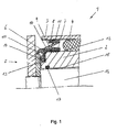
Fig. 1 ein Lager mit einem Dichtelement; -
Fig. 2 im Detail das inFigur 1 -
Fig. 3 ein Lager mit einem Dichtelement; -
Fig. 4 im Detail das inFigur 3
-
Fig. 1 a bearing with a sealing element; -
Fig. 2 in detail the inFIG. 1 shown sealing element; -
Fig. 3 a bearing with a sealing element; -
Fig. 4 in detail the inFIG. 3 shown sealing element.
Claims (10)
Applications Claiming Priority (1)
| Application Number | Priority Date | Filing Date | Title |
|---|---|---|---|
| DE102008028115A DE102008028115A1 (en) | 2008-06-13 | 2008-06-13 | camp |
Publications (2)
| Publication Number | Publication Date |
|---|---|
| EP2133590A2 true EP2133590A2 (en) | 2009-12-16 |
| EP2133590A3 EP2133590A3 (en) | 2014-07-02 |
Family
ID=41055207
Family Applications (1)
| Application Number | Title | Priority Date | Filing Date |
|---|---|---|---|
| EP09007641.5A Withdrawn EP2133590A3 (en) | 2008-06-13 | 2009-06-10 | Bearing |
Country Status (5)
| Country | Link |
|---|---|
| US (1) | US8210543B2 (en) |
| EP (1) | EP2133590A3 (en) |
| CN (1) | CN101660582B (en) |
| DE (1) | DE102008028115A1 (en) |
| RU (1) | RU2415318C2 (en) |
Cited By (2)
| Publication number | Priority date | Publication date | Assignee | Title |
|---|---|---|---|---|
| US10808756B2 (en) | 2007-04-13 | 2020-10-20 | Waukesha Bearings Corporation | Compliant bearing |
| EP4353997A1 (en) * | 2022-10-13 | 2024-04-17 | Freudenberg-NOK General Partnership | High pressure offset seal |
Families Citing this family (11)
| Publication number | Priority date | Publication date | Assignee | Title |
|---|---|---|---|---|
| GB2463873A (en) * | 2008-09-24 | 2010-03-31 | Walker & Co James Ltd | An energised seal |
| US9746081B2 (en) * | 2009-08-25 | 2017-08-29 | Freudenberg-Nok General Partnership | Low load offset seal |
| DE102011056013B4 (en) * | 2011-12-05 | 2024-03-28 | Dr. Ing. H.C. F. Porsche Aktiengesellschaft | Multi-part guide bearing for use in a vehicle bearing block |
| US20130307228A1 (en) * | 2012-05-18 | 2013-11-21 | Freudenberg-Nok General Partnership | Low Load Seal With Outer Diameter Flap |
| DE102014102715B3 (en) * | 2014-02-28 | 2015-07-16 | Jenoptik Optical Systems Gmbh | Low-tension socket assembly |
| DE102015100429B4 (en) | 2015-01-13 | 2018-07-26 | Trelleborgvibracoustic Gmbh | Compensating diaphragm for a hydraulically damping bearing |
| US10415642B2 (en) * | 2015-06-09 | 2019-09-17 | Aktiebolaget Skf | Coupling system of a sealing assembly with a rotating annular element |
| CN106438715B (en) | 2015-08-07 | 2020-03-17 | 舍弗勒技术股份两合公司 | Sealing structure for bearing |
| CN108343703B (en) * | 2017-01-23 | 2020-09-22 | 株洲时代瑞唯减振装备有限公司 | Rigidity adjusting device for hydraulic bushing and hydraulic bushing |
| WO2021014798A1 (en) | 2019-07-24 | 2021-01-28 | Nok株式会社 | Sealing device |
| DE102019133637A1 (en) * | 2019-12-10 | 2021-06-10 | Audi Ag | Hydraulic bearing and method of making a hydraulic bearing |
Citations (1)
| Publication number | Priority date | Publication date | Assignee | Title |
|---|---|---|---|---|
| DE10220219B4 (en) | 2002-05-06 | 2006-04-13 | Zf Boge Elastmetall Gmbh | Rubber bearing |
Family Cites Families (24)
| Publication number | Priority date | Publication date | Assignee | Title |
|---|---|---|---|---|
| US2997318A (en) * | 1957-08-01 | 1961-08-22 | Parker Hannifin Corp | Sealing rings for rods and shafts |
| GB1150954A (en) * | 1966-09-16 | 1969-05-07 | Birfield Eng Ltd | Improvements in or relating to Flexible Seals |
| US3948574A (en) * | 1975-06-19 | 1976-04-06 | J. I. Case Company | Joint with a combined seal and bushing |
| US4156532A (en) * | 1975-12-28 | 1979-05-29 | Toyota Jidosha Kogyo Kabushiki Kaisha | Sealing device for an automobile disk brake |
| US4228726A (en) * | 1978-08-01 | 1980-10-21 | Kelsey Hayes Co. | Hydraulic disc brake piston seal |
| JPS5592961U (en) * | 1978-12-20 | 1980-06-27 | ||
| US4537289A (en) * | 1982-06-18 | 1985-08-27 | International Telephone And Telegraph Corporation | Dust boot for a disc-brake actuating cylinder-and-piston unit |
| US4809821A (en) * | 1983-11-14 | 1989-03-07 | Allied-Signal Inc. | Disc brake corrosion barrier |
| DE3765249D1 (en) * | 1986-03-24 | 1990-10-31 | Zahnradfabrik Friedrichshafen | SEALING RING FOR ARRANGEMENT BETWEEN AXIAL AND ROTATING MACHINE PARTS. |
| DE3740310A1 (en) * | 1987-11-27 | 1989-06-08 | Porsche Ag | REAR SUSPENSION FOR A MOTOR VEHICLE |
| JP2647687B2 (en) * | 1988-04-26 | 1997-08-27 | 倉敷化工株式会社 | Bush assembly |
| US5348337A (en) * | 1991-12-27 | 1994-09-20 | Mazda Motor Corporation | Automobile suspension |
| DE4322304C1 (en) * | 1993-07-05 | 1994-11-24 | Joern Gmbh | Pivot bearing, particularly for an axle guide of a motor vehicle |
| US5626520A (en) * | 1995-06-14 | 1997-05-06 | The Zeller Corporation | Reversible universal joint seal |
| JPH11126648A (en) * | 1997-10-21 | 1999-05-11 | Yazaki Corp | Packing holding structure |
| JP4052705B2 (en) * | 1998-01-14 | 2008-02-27 | 本田技研工業株式会社 | Liquid-filled bush |
| US6298955B1 (en) * | 1999-10-26 | 2001-10-09 | Meritor Heavy Vehicle Systems, Llc | Shaft seal for eccentric air brake lever |
| JP3548083B2 (en) | 2000-03-31 | 2004-07-28 | 立川機工株式会社 | Decorative curtain rail mounting bracket |
| DE10024536B4 (en) * | 2000-05-18 | 2006-06-01 | Trelleborg Automotive Technical Centre Gmbh | Hydraulically damping bush |
| US7097004B2 (en) * | 2003-01-24 | 2006-08-29 | Akebono Corporation (North America) | Pressure bleeding boot-type seal |
| US6827649B2 (en) * | 2003-03-12 | 2004-12-07 | American Axle & Manufacturing, Inc. | Universal joint with friction fit and bearing cup retainer |
| US20060220323A1 (en) * | 2005-03-31 | 2006-10-05 | Frostick Lewis A | Static flexible seal |
| DE102006003194A1 (en) * | 2006-01-24 | 2007-08-02 | Elringklinger Ag | radial seal |
| CN201023406Y (en) * | 2007-01-08 | 2008-02-20 | 许容毅 | Swinging arm suspension lining |
-
2008
- 2008-06-13 DE DE102008028115A patent/DE102008028115A1/en not_active Ceased
-
2009
- 2009-06-10 EP EP09007641.5A patent/EP2133590A3/en not_active Withdrawn
- 2009-06-11 RU RU2009122594/11A patent/RU2415318C2/en not_active IP Right Cessation
- 2009-06-12 CN CN2009102057179A patent/CN101660582B/en not_active Expired - Fee Related
- 2009-06-12 US US12/456,183 patent/US8210543B2/en active Active
Patent Citations (1)
| Publication number | Priority date | Publication date | Assignee | Title |
|---|---|---|---|---|
| DE10220219B4 (en) | 2002-05-06 | 2006-04-13 | Zf Boge Elastmetall Gmbh | Rubber bearing |
Cited By (2)
| Publication number | Priority date | Publication date | Assignee | Title |
|---|---|---|---|---|
| US10808756B2 (en) | 2007-04-13 | 2020-10-20 | Waukesha Bearings Corporation | Compliant bearing |
| EP4353997A1 (en) * | 2022-10-13 | 2024-04-17 | Freudenberg-NOK General Partnership | High pressure offset seal |
Also Published As
| Publication number | Publication date |
|---|---|
| US8210543B2 (en) | 2012-07-03 |
| CN101660582A (en) | 2010-03-03 |
| EP2133590A3 (en) | 2014-07-02 |
| CN101660582B (en) | 2012-03-21 |
| RU2415318C2 (en) | 2011-03-27 |
| US20090309314A1 (en) | 2009-12-17 |
| DE102008028115A1 (en) | 2009-12-24 |
| RU2009122594A (en) | 2010-12-20 |
Similar Documents
| Publication | Publication Date | Title |
|---|---|---|
| EP2133590A2 (en) | Bearing | |
| EP2616700B1 (en) | Peripheral sealing arrangement | |
| EP1585905B1 (en) | Gasket unit for a bearing bushing | |
| EP1731804A1 (en) | Sealing and assembly provided with sealing lips in series | |
| EP3458746B1 (en) | Rotary seal assembly with pressure-activatable rotary seal, and rotary seal | |
| EP1132642B1 (en) | Rubber support | |
| DE102004031559A1 (en) | Elastomeric bush bearing with improved torsional behavior | |
| DE102005039741A1 (en) | Seal for shaft and/or radial roller bearing, has sealing unit surrounded by circular sealing shoe that forms hollow space with tapered chamber wall, where sealing lips of sealing unit are accommodated in tapered chamber wall | |
| DE102017108717A1 (en) | Disc brake for a commercial vehicle | |
| EP1243802A2 (en) | Bearing device for a shaft bearing | |
| EP1783384B1 (en) | Universal joint assembly | |
| DE102018205047A1 (en) | Thrust washer, bearing assembly and gearbox | |
| EP1477694B1 (en) | Sealing arrangement for sealing the gap between a bearing bush and shaft | |
| EP1736676A1 (en) | Rolling bearing with a sealing element | |
| DE102018105393B3 (en) | Sealing ring and seal assembly comprising the sealing ring | |
| DE102020130310A1 (en) | Unit for a universal joint bearing | |
| WO2015067364A1 (en) | Wiper arrangement and/or sealing arrangement, and wiper and/or sealing ring therefor | |
| EP3502524A1 (en) | Sliding seal and assembly with such a seal | |
| DE19955859B4 (en) | Mechanical seal | |
| DE4109133C2 (en) | Sealing arrangement for sealing a trunnion cross of a universal joint | |
| DE102010012844B4 (en) | Seal with barrel sleeve with lubrication pockets | |
| WO2012100792A1 (en) | Sealing ring | |
| DE202016102691U1 (en) | Rotary sealing arrangement with pressure-activated rotary seal and rotary seal | |
| DE19705409A1 (en) | Sealing ring | |
| EP2466172A1 (en) | Gasket |
Legal Events
| Date | Code | Title | Description |
|---|---|---|---|
| PUAI | Public reference made under article 153(3) epc to a published international application that has entered the european phase |
Free format text: ORIGINAL CODE: 0009012 |
|
| AK | Designated contracting states |
Kind code of ref document: A2 Designated state(s): AT BE BG CH CY CZ DE DK EE ES FI FR GB GR HR HU IE IS IT LI LT LU LV MC MK MT NL NO PL PT RO SE SI SK TR |
|
| PUAL | Search report despatched |
Free format text: ORIGINAL CODE: 0009013 |
|
| AK | Designated contracting states |
Kind code of ref document: A3 Designated state(s): AT BE BG CH CY CZ DE DK EE ES FI FR GB GR HR HU IE IS IT LI LT LU LV MC MK MT NL NO PL PT RO SE SI SK TR |
|
| AX | Request for extension of the european patent |
Extension state: AL BA RS |
|
| RIC1 | Information provided on ipc code assigned before grant |
Ipc: F16F 13/14 20060101AFI20140523BHEP |
|
| STAA | Information on the status of an ep patent application or granted ep patent |
Free format text: STATUS: THE APPLICATION IS DEEMED TO BE WITHDRAWN |
|
| 18D | Application deemed to be withdrawn |
Effective date: 20150106 |