DE102008064231B4 - Cooling device for a vehicle engine - Google Patents
Cooling device for a vehicle engine Download PDFInfo
- Publication number
- DE102008064231B4 DE102008064231B4 DE200810064231 DE102008064231A DE102008064231B4 DE 102008064231 B4 DE102008064231 B4 DE 102008064231B4 DE 200810064231 DE200810064231 DE 200810064231 DE 102008064231 A DE102008064231 A DE 102008064231A DE 102008064231 B4 DE102008064231 B4 DE 102008064231B4
- Authority
- DE
- Germany
- Prior art keywords
- engine
- cooling water
- radiator
- passage
- surge tank
- Prior art date
- Legal status (The legal status is an assumption and is not a legal conclusion. Google has not performed a legal analysis and makes no representation as to the accuracy of the status listed.)
- Active
Links
Images


Classifications
-
- F—MECHANICAL ENGINEERING; LIGHTING; HEATING; WEAPONS; BLASTING
- F01—MACHINES OR ENGINES IN GENERAL; ENGINE PLANTS IN GENERAL; STEAM ENGINES
- F01P—COOLING OF MACHINES OR ENGINES IN GENERAL; COOLING OF INTERNAL-COMBUSTION ENGINES
- F01P11/00—Component parts, details, or accessories not provided for in, or of interest apart from, groups F01P1/00 - F01P9/00
- F01P11/04—Arrangements of liquid pipes or hoses
-
- B—PERFORMING OPERATIONS; TRANSPORTING
- B60—VEHICLES IN GENERAL
- B60K—ARRANGEMENT OR MOUNTING OF PROPULSION UNITS OR OF TRANSMISSIONS IN VEHICLES; ARRANGEMENT OR MOUNTING OF PLURAL DIVERSE PRIME-MOVERS IN VEHICLES; AUXILIARY DRIVES FOR VEHICLES; INSTRUMENTATION OR DASHBOARDS FOR VEHICLES; ARRANGEMENTS IN CONNECTION WITH COOLING, AIR INTAKE, GAS EXHAUST OR FUEL SUPPLY OF PROPULSION UNITS IN VEHICLES
- B60K11/00—Arrangement in connection with cooling of propulsion units
- B60K11/02—Arrangement in connection with cooling of propulsion units with liquid cooling
-
- F—MECHANICAL ENGINEERING; LIGHTING; HEATING; WEAPONS; BLASTING
- F01—MACHINES OR ENGINES IN GENERAL; ENGINE PLANTS IN GENERAL; STEAM ENGINES
- F01P—COOLING OF MACHINES OR ENGINES IN GENERAL; COOLING OF INTERNAL-COMBUSTION ENGINES
- F01P11/00—Component parts, details, or accessories not provided for in, or of interest apart from, groups F01P1/00 - F01P9/00
- F01P11/02—Liquid-coolant filling, overflow, venting, or draining devices
- F01P11/029—Expansion reservoirs
-
- F—MECHANICAL ENGINEERING; LIGHTING; HEATING; WEAPONS; BLASTING
- F01—MACHINES OR ENGINES IN GENERAL; ENGINE PLANTS IN GENERAL; STEAM ENGINES
- F01P—COOLING OF MACHINES OR ENGINES IN GENERAL; COOLING OF INTERNAL-COMBUSTION ENGINES
- F01P11/00—Component parts, details, or accessories not provided for in, or of interest apart from, groups F01P1/00 - F01P9/00
- F01P11/10—Guiding or ducting cooling-air, to, or from, liquid-to-air heat exchangers
-
- F—MECHANICAL ENGINEERING; LIGHTING; HEATING; WEAPONS; BLASTING
- F01—MACHINES OR ENGINES IN GENERAL; ENGINE PLANTS IN GENERAL; STEAM ENGINES
- F01P—COOLING OF MACHINES OR ENGINES IN GENERAL; COOLING OF INTERNAL-COMBUSTION ENGINES
- F01P2070/00—Details
- F01P2070/52—Details mounting heat-exchangers
Landscapes
- Engineering & Computer Science (AREA)
- Chemical & Material Sciences (AREA)
- Combustion & Propulsion (AREA)
- Mechanical Engineering (AREA)
- Transportation (AREA)
- General Engineering & Computer Science (AREA)
- Cooling, Air Intake And Gas Exhaust, And Fuel Tank Arrangements In Propulsion Units (AREA)
Abstract
Kühlvorrichtung eines Motors für ein Fahrzeug, die auf eine solche Weise aufgebaut ist, dass ein Kühler, der in den beiden Seitenabschnitten in der Fahrzeugbreitenrichtung einen Kühlwassereinlass (7) und einen Kühlwasserauslass (8) aufweist, unter einem oberen Element (5) angeordnet ist, das in einem vorderen Abschnitt eines Motorraums angeordnet ist, der Motor, der an Positionen neben dem Kühlwassereinlass (7) und dem Kühlwasserauslass (8) des Kühlers einen Kühlwasserauslass (8) bzw. einen Kühlwassereinlass (7) aufweist, hinter dem Kühler angeordnet ist, der Kühlwasserauslass (8) des Motors und der Kühlwassereinlass des Kühlers durch einen Motorauslassdurchgang (18) verbunden sind, der Kühlwasserauslass des Kühlers und der Kühlwassereinlass des Motors durch einen Motoreinlassdurchgang (19) verbunden sind, ein Druckausgleichsbehälter (20) an einer Position, die in der Fahrzeugbreitenrichtung vom Motoreinlassdurchgang (19) entfernt ist, angeordnet ist, ein oberer Abschnitt eines Kühlwasserdurchgangs im Motor und der Druckausgleichsbehälter (20) durch einen Ausgleichsbehältereinlassdurchgang (23) verbunden sind, und der Druckausgleichsbehälter (20) und der Motoreinlassdurchgang (19) durch einen Ausgleichsbehälterauslassdurchgang, der einen Kernabschnitt (9) des Kühlers umgeht, verbunden sind, wobei zwischen dem Kühler und dem oberen Element (5) ein Raumabschnitt (26) gebildet ist, durch den Fahrtwind verläuft, und ein Teil des Ausgleichsbehälterauslassdurchgangs aus einem Metallrohr besteht, das sich in der Fahrzeugbreitenrichtung erstreckt, und im Raumabschnitt (26) angeordnet ist.A cooling device of an engine for a vehicle, which is constructed in such a manner that a radiator having a cooling water inlet (7) and a cooling water outlet (8) in the two side sections in the vehicle width direction is disposed below an upper member (5), is disposed in a front portion of an engine compartment, the engine having a cooling water outlet (8) and a cooling water inlet (7) at positions adjacent to the cooling water inlet (7) and the cooling water outlet (8) of the radiator is disposed behind the radiator, the cooling water outlet (8) of the engine and the cooling water inlet of the radiator are connected through an engine exhaust passage (18), the cooling water outlet of the radiator and the cooling water inlet of the engine are connected through an engine inlet passage (19), a surge tank (20) at a position in the vehicle width direction from the engine inlet passage (19) is removed, an upper Absch of a cooling water passage in the engine and the surge tank (20) are connected through a surge tank inlet passage (23), and the surge tank (20) and the engine intake passage (19) are connected through a surge tank outlet passage bypassing a core portion (9) of the radiator between the radiator and the upper member (5) is formed a space portion (26) through which airflow passes, and a part of the reservoir outlet passage is made of a metal pipe extending in the vehicle width direction and disposed in the space portion (26).
Description
Die Erfindung betrifft eine Kühlvorrichtung eines Motors für ein Fahrzeug, und genauer eine Kühlvorrichtung eines Motors für ein Fahrzeug, wobei die Kühleffizienz des Motors verbessert ist.The invention relates to a cooling device of an engine for a vehicle, and more particularly to a cooling device of an engine for a vehicle, wherein the cooling efficiency of the engine is improved.
Unter den Motoren für Fahrzeuge gibt es einen Motor, der eine Kühlvorrichtung vom Wasserkühlungstyp aufweist, um jeden Abschnitt im Motor durch eine Zwangsumwälzung von Kühlwasser durch eine Wasserpumpe zu kühlen, um jeden Abschnitt im Motor bei einer richtigen Temperatur zu halten.Among the engines for vehicles, there is an engine having a water-cooling type cooling device for cooling each section in the engine by forcibly circulating cooling water through a water pump to keep each section in the engine at a proper temperature.
Bei der Kühlvorrichtung des Motors für das Fahrzeug nach dem Stand der Technik wird das durch den Motor erhitzte Kühlwasser durch die Wasserpumpe in einem Kühler umgewälzt und gekühlt.In the engine cooling apparatus for the vehicle of the prior art, the cooling water heated by the engine is circulated by the water pump in a radiator and cooled.
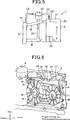
Die Erklärung wird unter Verwendung der Bezugszeichen in
Wie in
Der obere Abschnitt
Wenn sich der Kühlwasserdurchgang im Motor an einer Position befindet, die höher als der Kühler liegt, wird das Kühlwasser somit in den Druckausgleichsbehälter, der an einer Position angeordnet ist, die höher als der Kühlwasserdurchgang im Motor liegt, umgewälzt, wodurch das Kühlwasser entlüftet wird.Thus, when the cooling water passage in the engine is at a position higher than the radiator, the cooling water is circulated into the surge tank disposed at a position higher than the cooling water passage in the engine, thereby venting the cooling water.
Dabei ist der Ausgleichsbehälterauslassdurchgang zum Zurückführen des Kühlwassers vom Druckausgleichsbehälter zum Motor durch einen Pfad, der den Kernabschnitt des Kühlers umgeht, mit der Ansaugseite der Wasserpumpe verbunden, um das Kühlwasser verlässlich zum Druckausgleichsbehälter umzuwälzen.At this time, the surge tank outlet passage for returning the cooling water from the surge tank to the engine through a path bypassing the core portion of the radiator is connected to the suction side of the water pump to reliably circulate the cooling water to the surge tank.
Doch im Fall des obigen Aufbaus besteht die Unannehmlichkeit, dass die Kühleffizienz des Motors schlecht wird, da das Kühlwasser, das durch den Druckausgleichsbehälter verläuft, zum Motor zurückgeführt wird, ohne durch den Kühler gekühlt zu werden.However, in the case of the above construction, there is the inconvenience that the cooling efficiency of the engine becomes poor because the cooling water passing through the surge tank is returned to the engine without being cooled by the radiator.
In dem Fall, in dem der Druckausgleichsbehälter im Motorraum in der Nähe des Kühlwassereinlasses des Kühlers angeordnet ist, ist der Ausgleichsbehälterauslassdurchgang häufig durch einen Zwischenraum zwischen dem Kühler und dem Motor mit dem Motorauslassdurchgang verbunden. Folglich besteht die Unannehmlichkeit, dass der Durchgangsaufbau zur Vermeidung einer gegenseitigen Behinderung mit anderen Teilen kompliziert wird und die Effizienz der Montage am Fahrzeug schlecht wird.In the case where the surge tank is disposed in the engine compartment near the radiator water inlet of the radiator, the surge tank outlet passage is often connected to the engine outlet passage through a gap between the radiator and the engine. As a result, there is an inconvenience that the passage structure becomes complicated to prevent mutual interference with other parts and the efficiency of mounting on the vehicle becomes poor.
Darüber hinaus ist aus
Aus
Weiterhin offenbaren noch
Weiterhin
Darüber hinaus wurde in
Eine Aufgabe der Erfindung ist, die Kühleffizienz des Motors zu verbessern.An object of the invention is to improve the cooling efficiency of the engine.
Eine andere Aufgabe der Erfindung ist, einen Aufbau der Teile der Kühlvorrichtung des Motors zu vereinfachen.Another object of the invention is to simplify a structure of the parts of the cooling device of the engine.
Noch eine andere Aufgabe der Erfindung ist, die Montageeffizienz des Fahrzeugs zu verbessern.Yet another object of the invention is to improve the assembly efficiency of the vehicle.
Demgemäß wird eine Kühlvorrichtung eines Motors für ein Fahrzeug, die auf eine solche Weise aufgebaut ist, dass ein Kühler, der in den beiden Seitenabschnitten in der Fahrzeugbreitenrichtung einen Kühlwassereinlass und einen Kühlwasserauslass aufweist, unter einem oberen Element angeordnet ist, das in einem vorderen Abschnitt eines Motorraums angeordnet ist, der Motor, der an Positionen neben dem Kühlwassereinlass und dem Kühlwasserauslass des Kühlers einen Kühlwasserauslass bzw. einen Kühlwassereinlass aufweist, hinter dem Kühler angeordnet ist, der Kühlwasserauslass des Motors und der Kühlwassereinlass des Kühlers durch einen Motorauslassdurchgang verbunden sind, der Kühlwasserauslass des Kühlers und der Kühlwassereinlass des Motors durch einen Motoreinlassdurchgang verbunden sind, ein Druckausgleichsbehälter an einer Position, die in der Fahrzeugbreitenrichtung vom Motoreinlassdurchgang entfernt ist, angeordnet ist, ein oberer Abschnitt eines Kühlwasserdurchgangs im Motor und der Druckausgleichsbehälter durch einen Ausgleichsbehältereinlassdurchgang verbunden sind, und der Druckausgleichsbehälter und der Motoreinlassdurchgang durch einen Ausgleichsbehälterauslassdurchgang, der einen Kernabschnitt des Kühlers umgeht, verbunden sind, bereitgestellt, wobei zwischen dem Kühler und dem oberen Element ein Raumabschnitt gebildet ist, durch den ein Fahrtwind verläuft, und ein Teil des Ausgleichsbehälterauslassdurchgangs aus einem Metallrohr besteht, das sich in der Fahrzeugbreitenrichtung erstreckt, und im Raumabschnitt angeordnet ist.Accordingly, a cooling device of an engine for a vehicle constructed in such a manner that a radiator having a cooling water inlet and a cooling water outlet in the two side sections in the vehicle width direction is disposed below an upper member formed in a front portion of a vehicle Engine compartment is arranged, the engine having at positions adjacent to the cooling water inlet and the cooling water outlet of the radiator Kühlwasserauslass or a cooling water inlet, is arranged behind the radiator, the cooling water outlet of the engine and the cooling water inlet of the radiator through an engine outlet passage, the cooling water outlet of the Radiator and the cooling water inlet of the engine are connected by an engine inlet passage, a surge tank at a position which is removed in the vehicle width direction from the engine intake passage, an upper portion of a cooling water passage s in the engine and the surge tank are connected through a surge tank inlet passage, and the surge tank and the engine intake passage are connected by a surge tank outlet passage bypassing a core portion of the cooler, wherein a space portion is formed between the radiator and the upper member through which Running wind is, and a part of the surge tank outlet passage consists of a metal pipe which extends in the vehicle width direction, and is arranged in the space portion.
Nach der Erfindung ist in der Kühlvorrichtung des Motors für das Fahrzeug, die auf eine solche Weise aufgebaut ist, dass der Kühler, der in den beiden Seitenabschnitten in der Fahrzeugbreitenrichtung den Kühlwassereinlass und den Kühlwasserauslass aufweist, unter dem oberen Element angeordnet ist, das im vorderen Abschnitt des Motorraums angeordnet ist, der Motor, der an den Positionen neben dem Kühlwassereinlass und dem Kühlwasserauslass des Kühlers den Kühlwasserauslass bzw. den Kühlwassereinlass aufweist, hinter dem Kühler angeordnet ist, der Kühlwasserauslass des Motors und der Kühlwassereinlass des Kühlers durch den Motorauslassdurchgang verbunden sind, der Kühlwasserauslass des Kühlers und der Kühlwassereinlass des Motors durch den Motoreinlassdurchgang verbunden sind, der Druckausgleichsbehälter an der Position, die in der Fahrzeugbreitenrichtung vom Motoreinlassdurchgang entfernt ist, angeordnet ist, der obere Abschnitt des Kühlwasserdurchgangs im Motor und der Druckausgleichsbehälter durch den Ausgleichsbehältereinlassdurchgang verbunden sind, und der Druckausgleichsbehälter und der Motoreinlassdurchgang durch den Ausgleichsbehälterauslassdurchgang, der den Kernabschnitt des Kühlers umgeht, verbunden sind, zwischen dem Kühler und dem oberen Element der Raumabschnitt gebildet, durch den der Fahrtwind verläuft, und besteht der Teil des Ausgleichsbehälterauslassdurchgangs aus dem Metallrohr, das sich in der Fahrzeugbreitenrichtung erstreckt, und ist er im Raumabschnitt angeordnet.According to the invention, in the cooling device of the engine for the vehicle, which is constructed in such a manner that the radiator having the cooling water inlet and the cooling water outlet in the two side sections in the vehicle width direction is disposed below the upper element, that in the front Is disposed portion of the engine room, the engine having the cooling water outlet and the cooling water inlet at the positions adjacent to the cooling water inlet and the cooling water outlet of the radiator is disposed behind the radiator, the cooling water outlet of the engine and the cooling water inlet of the radiator are connected through the engine exhaust passage, the cooling water outlet of the radiator and the cooling water inlet of the engine are connected through the engine intake passage, the surge tank is disposed at the position away in the vehicle width direction from the engine intake passage, the upper portion of the cooling water passage in the engine and d the surge tank and the engine inlet passage are connected by the surge tank outlet passage which bypasses the core portion of the radiator, formed between the radiator and the upper member of the space portion through which the running wind passes, and is the part of Ausgleichsbehälterauslassdurchgangs from the metal tube, which extends in the vehicle width direction, and it is arranged in the space portion.
Da der Raum, durch den der Fahrtwind verläuft, zwischen dem Kühler und dem oberen Element gebildet ist, kann somit die Menge des Fahrtwinds, der über den Kühler verläuft, erhöht werden. Da ein Teil des Ausgleichsbehälterauslassdurchgangs aus dem Metallrohr gebildet ist, das sich in der Fahrzeugbreitenrichtung erstreckt, und im Raumabschnitt über dem Kühler angeordnet ist, wird ferner das Kühlwasser mit einer hohen Temperatur, das im Ausgleichsbehälterauslassdurchgang fließt, durch den Fahrtwind gekühlt, wird die Temperatur des Kühlwassers, das in den Motor fließt, verringert, und kann die Kühleffizienz des Motors verbessert werden. Da keine Notwendigkeit besteht, den Ausgleichsbehälterauslassdurchgang in dem engen Raum, der zwischen den Kühler und den Motor eingezwängt ist, anzuordnen, kann der Ausgleichsbehälterauslassdurchgang vereinfacht werden und die Effizienz der Montage am Fahrzeug verbessert werden.Thus, since the space through which the running wind passes is formed between the radiator and the upper member, the amount of the running wind passing over the radiator can be increased. Further, since a part of the surge tank outlet passage is formed of the metal pipe extending in the vehicle width direction and disposed in the space portion above the radiator, the high temperature cooling water flowing in the surge tank outlet passage is cooled by the running wind Cooling water that flows into the engine, reduced, and the cooling efficiency of the engine can be improved. Since there is no need to arrange the surge tank outlet passage in the narrow space sandwiched between the radiator and the engine, the surge tank outlet passage can be simplified and the efficiency of mounting on the vehicle can be improved.
Damit die Art und Weise der oben angeführten Merkmale der vorliegenden Erfindung im Einzelnen verstanden werden kann, kann eine genauere Beschreibung der oben kurz zusammengefassten Erfindung unter Bezugnahme auf verschiedene Ausführungsformen, wovon einige in den beiliegenden Zeichnungen veranschaulicht sind, erhalten werden. Es soll jedoch bemerkt werden, dass die beiliegenden Zeichnungen nur typische Ausführungsformen dieser Erfindung zeigen und daher nicht als Beschränkung ihres Umfangs betrachtet werden sollen, da die Erfindung andere gleichermaßen wirksame Ausführungsformen zulassen kann.In order that the manner of the above-mentioned features of the present invention can be understood in detail, a more detailed description of the above briefly summarized Invention with reference to various embodiments, some of which are illustrated in the accompanying drawings. It is to be understood, however, that the appended drawings illustrate only typical embodiments of this invention and are therefore not to be considered as limiting its scope, for the invention may admit to other equally effective embodiments.
In
Nach einer Ausführungsform der Erfindung weist der Kühler
Wie in
In diesem Fall ist die Gebläseabdeckung
An den Positionen neben dem Kühlerkühlwassereinlass
Wie in
Ferner sind wie in
Wie in
Daher wird das Kühlwasser, das durch das Kühlen des Motors
Da sich der obere Abschnitt
Zur ausführlicheren Erklärung wird die Luft, die im oberen Abschnitt
Die Kühlvorrichtung
Nach einer Ausführungsform der Erfindung ist der Raumabschnitt
Da der Raumabschnitt
Wie in
Da ein Teil des Ausgleichsbehälterauslassdurchgangs
Da keine Notwendigkeit besteht, den Ausgleichsbehälterauslassdurchgang
Ferner ist der Kühler
Ferner ist wie in
Im Fall des Dieselmotors ist die Schwingung stark und wird die starke Schwingung vom Motor
Die Effizienz der Montage am Fahrzeug kann verglichen mit dem Fall des unabhängigen Anbringens des Kühlers
Nach einer Ausführungsform der Erfindung (wie in
Wie in
Da die Fixierungspunkte
Da der gekrümmte Abschnitt
Obwohl das Obige auf Ausführungsformen der vorliegenden Erfindung gerichtet ist, können andere und weitere Ausführungsformen der Erfindung erdacht werden, ohne von deren grundlegendem Umfang abzuweichen, und wird ihr Umfang durch die folgenden Ansprüche bestimmt.Although the above is directed to embodiments of the present invention, other and further embodiments of the invention may be devised without departing from the essential scope thereof, and its scope will be determined by the following claims.
Claims (3)
Applications Claiming Priority (2)
| Application Number | Priority Date | Filing Date | Title |
|---|---|---|---|
| JP2007340473A JP5071797B2 (en) | 2007-12-28 | 2007-12-28 | Cooling device for vehicle engine |
| JP2007-340473 | 2007-12-28 |
Publications (2)
| Publication Number | Publication Date |
|---|---|
| DE102008064231A1 DE102008064231A1 (en) | 2009-07-09 |
| DE102008064231B4 true DE102008064231B4 (en) | 2013-07-04 |
Family
ID=40719580
Family Applications (1)
| Application Number | Title | Priority Date | Filing Date |
|---|---|---|---|
| DE200810064231 Active DE102008064231B4 (en) | 2007-12-28 | 2008-12-22 | Cooling device for a vehicle engine |
Country Status (2)
| Country | Link |
|---|---|
| JP (1) | JP5071797B2 (en) |
| DE (1) | DE102008064231B4 (en) |
Families Citing this family (3)
| Publication number | Priority date | Publication date | Assignee | Title |
|---|---|---|---|---|
| JP5776556B2 (en) * | 2012-01-05 | 2015-09-09 | トヨタ自動車株式会社 | Piping fixing structure |
| JP5888425B2 (en) * | 2012-09-20 | 2016-03-22 | 日産自動車株式会社 | Vehicle cooling system |
| DE102017123468A1 (en) | 2017-10-10 | 2019-04-11 | Volkswagen Aktiengesellschaft | Method for operating an internal combustion engine, internal combustion engine and motor vehicle |
Citations (6)
| Publication number | Priority date | Publication date | Assignee | Title |
|---|---|---|---|---|
| US1985198A (en) * | 1933-05-12 | 1934-12-18 | Carbide & Carbon Chem Corp | Cooling system |
| US2543443A (en) * | 1948-08-05 | 1951-02-27 | Harland F Beardslee | Auxiliary heat radiator for internal-combustion engines |
| JPS60107321U (en) * | 1983-12-21 | 1985-07-22 | 三菱自動車工業株式会社 | Internal combustion engine cooling system |
| JPH10213033A (en) * | 1997-01-31 | 1998-08-11 | Suzuki Motor Corp | Intake structure of internal combustion engine |
| JP2004270661A (en) * | 2003-03-12 | 2004-09-30 | Suzuki Motor Corp | Degassing tank bracket for vehicle |
| JP2004284514A (en) * | 2003-03-24 | 2004-10-14 | Suzuki Motor Corp | Mounting structure of cooling fan for engine |
Family Cites Families (5)
| Publication number | Priority date | Publication date | Assignee | Title |
|---|---|---|---|---|
| JPS61162530U (en) * | 1985-03-29 | 1986-10-08 | ||
| JPS6221432U (en) * | 1985-07-25 | 1987-02-09 | ||
| JPH0714730A (en) | 1993-06-15 | 1995-01-17 | Japan Aviation Electron Ind Ltd | Noncontact connector |
| JP2006266089A (en) * | 2005-03-22 | 2006-10-05 | Calsonic Kansei Corp | Piping structure of radiator core support |
| JP2007090962A (en) * | 2005-09-27 | 2007-04-12 | Denso Corp | Arrangement configuration of radiator peripheral part |
-
2007
- 2007-12-28 JP JP2007340473A patent/JP5071797B2/en not_active Expired - Fee Related
-
2008
- 2008-12-22 DE DE200810064231 patent/DE102008064231B4/en active Active
Patent Citations (6)
| Publication number | Priority date | Publication date | Assignee | Title |
|---|---|---|---|---|
| US1985198A (en) * | 1933-05-12 | 1934-12-18 | Carbide & Carbon Chem Corp | Cooling system |
| US2543443A (en) * | 1948-08-05 | 1951-02-27 | Harland F Beardslee | Auxiliary heat radiator for internal-combustion engines |
| JPS60107321U (en) * | 1983-12-21 | 1985-07-22 | 三菱自動車工業株式会社 | Internal combustion engine cooling system |
| JPH10213033A (en) * | 1997-01-31 | 1998-08-11 | Suzuki Motor Corp | Intake structure of internal combustion engine |
| JP2004270661A (en) * | 2003-03-12 | 2004-09-30 | Suzuki Motor Corp | Degassing tank bracket for vehicle |
| JP2004284514A (en) * | 2003-03-24 | 2004-10-14 | Suzuki Motor Corp | Mounting structure of cooling fan for engine |
Also Published As
| Publication number | Publication date |
|---|---|
| JP5071797B2 (en) | 2012-11-14 |
| JP2009160980A (en) | 2009-07-23 |
| DE102008064231A1 (en) | 2009-07-09 |
Similar Documents
| Publication | Publication Date | Title |
|---|---|---|
| EP0417500B1 (en) | Cooling air guide in the front part of an automobile | |
| EP0893666B1 (en) | Cooling module | |
| DE102006060488B4 (en) | Structure of a turbocharger air cooler for engines | |
| DE102005004614A1 (en) | Heat exchanger cooling device for vehicle, has coolant heat radiator inclined with respect to a radiator along the downward side of the vehicle such that the lower gap between radiators is greater than the top gap | |
| DE3917108C1 (en) | ||
| DE60012440T2 (en) | Cowl construction for a motorcycle | |
| DE102010045100A1 (en) | Cooling device for hybrid vehicle | |
| DE102009031311A1 (en) | Cooling device for a fuel cell powered vehicle | |
| DE10250334A1 (en) | Heat exchanger arrangement for motor vehicles | |
| DE102013208969A1 (en) | Front air ducting of a motorcycle | |
| DE112014000492T5 (en) | Double-cooler machine cooling module with single coolant loop | |
| DE102006061826A1 (en) | Inlet system of a vehicle engine | |
| DE102017203858A1 (en) | Cooling device for a motor vehicle, fan cowl and an internal combustion engine having the cooling device | |
| DE102008064231B4 (en) | Cooling device for a vehicle engine | |
| DE102014201677B4 (en) | ASSEMBLY ARRANGEMENT FOR AN ELECTRIC WATER PUMP TO REDUCE THE SPREAD OF VIBRATIONS ON A VEHICLE BODY | |
| DE102006060085A1 (en) | Cooling module for motor vehicle has radiator, holding clamp, fan and cover, radiator being between cover and other components | |
| DE202016101418U1 (en) | Integrated NVH decoupler and front impact strut | |
| DE3841536C2 (en) | ||
| DE102016204917A1 (en) | Vehicle with a rear cooler | |
| DE3024312A1 (en) | FRONT CONSTRUCTION OF A VEHICLE | |
| EP1146210B1 (en) | Box-shaped cooling system for a motor car | |
| DE102017214489A1 (en) | Cooling device for a vehicle | |
| DE4227565C1 (en) | Car heat exchanger as transverse hollow profile - has open profile to front of vehicle with ducted air flow and with blower mounted on side of heat exchanger | |
| DE60116188T2 (en) | front end | |
| DE102018211671A1 (en) | Assembly structure for a charge air cooler of a vehicle |
Legal Events
| Date | Code | Title | Description |
|---|---|---|---|
| OP8 | Request for examination as to paragraph 44 patent law | ||
| R016 | Response to examination communication | ||
| R016 | Response to examination communication | ||
| R018 | Grant decision by examination section/examining division | ||
| R020 | Patent grant now final |
Effective date: 20131005 |