DE102013208969A1 - Front air ducting of a motorcycle - Google Patents

Front air ducting of a motorcycle Download PDF

Info

Publication number
DE102013208969A1
DE102013208969A1 DE102013208969A DE102013208969A DE102013208969A1 DE 102013208969 A1 DE102013208969 A1 DE 102013208969A1 DE 102013208969 A DE102013208969 A DE 102013208969A DE 102013208969 A DE102013208969 A DE 102013208969A DE 102013208969 A1 DE102013208969 A1 DE 102013208969A1
Authority
DE
Germany
Prior art keywords
air
bottom wall
guide
air inlet
vehicle width
Prior art date
Legal status (The legal status is an assumption and is not a legal conclusion. Google has not performed a legal analysis and makes no representation as to the accuracy of the status listed.)
Ceased
Application number
DE102013208969A
Other languages
German (de)
Inventor
Masahiro Kontani
Yoshinori KOROGI
Satoru Kubo
Takahiro Sano
Current Assignee (The listed assignees may be inaccurate. Google has not performed a legal analysis and makes no representation or warranty as to the accuracy of the list.)
Honda Motor Co Ltd
Original Assignee
Honda Motor Co Ltd
Priority date (The priority date is an assumption and is not a legal conclusion. Google has not performed a legal analysis and makes no representation as to the accuracy of the date listed.)
Filing date
Publication date
Application filed by Honda Motor Co Ltd filed Critical Honda Motor Co Ltd
Publication of DE102013208969A1 publication Critical patent/DE102013208969A1/en
Ceased legal-status Critical Current

Links

Images

Classifications

    • BPERFORMING OPERATIONS; TRANSPORTING
    • B62LAND VEHICLES FOR TRAVELLING OTHERWISE THAN ON RAILS
    • B62JCYCLE SADDLES OR SEATS; AUXILIARY DEVICES OR ACCESSORIES SPECIALLY ADAPTED TO CYCLES AND NOT OTHERWISE PROVIDED FOR, e.g. ARTICLE CARRIERS OR CYCLE PROTECTORS
    • B62J17/00Weather guards for riders; Fairings or stream-lining parts not otherwise provided for
    • B62J17/10Ventilation or air guiding devices forming part of fairings
    • BPERFORMING OPERATIONS; TRANSPORTING
    • B62LAND VEHICLES FOR TRAVELLING OTHERWISE THAN ON RAILS
    • B62KCYCLES; CYCLE FRAMES; CYCLE STEERING DEVICES; RIDER-OPERATED TERMINAL CONTROLS SPECIALLY ADAPTED FOR CYCLES; CYCLE AXLE SUSPENSIONS; CYCLE SIDE-CARS, FORECARS, OR THE LIKE
    • B62K11/00Motorcycles, engine-assisted cycles or motor scooters with one or two wheels
    • BPERFORMING OPERATIONS; TRANSPORTING
    • B62LAND VEHICLES FOR TRAVELLING OTHERWISE THAN ON RAILS
    • B62JCYCLE SADDLES OR SEATS; AUXILIARY DEVICES OR ACCESSORIES SPECIALLY ADAPTED TO CYCLES AND NOT OTHERWISE PROVIDED FOR, e.g. ARTICLE CARRIERS OR CYCLE PROTECTORS
    • B62J17/00Weather guards for riders; Fairings or stream-lining parts not otherwise provided for
    • B62J17/02Weather guards for riders; Fairings or stream-lining parts not otherwise provided for shielding only the rider's front
    • BPERFORMING OPERATIONS; TRANSPORTING
    • B62LAND VEHICLES FOR TRAVELLING OTHERWISE THAN ON RAILS
    • B62JCYCLE SADDLES OR SEATS; AUXILIARY DEVICES OR ACCESSORIES SPECIALLY ADAPTED TO CYCLES AND NOT OTHERWISE PROVIDED FOR, e.g. ARTICLE CARRIERS OR CYCLE PROTECTORS
    • B62J40/00Arrangements of air cleaners specially adapted for cycles
    • B62J40/10Arrangements of air cleaners specially adapted for cycles characterised by air duct arrangements
    • BPERFORMING OPERATIONS; TRANSPORTING
    • B62LAND VEHICLES FOR TRAVELLING OTHERWISE THAN ON RAILS
    • B62KCYCLES; CYCLE FRAMES; CYCLE STEERING DEVICES; RIDER-OPERATED TERMINAL CONTROLS SPECIALLY ADAPTED FOR CYCLES; CYCLE AXLE SUSPENSIONS; CYCLE SIDE-CARS, FORECARS, OR THE LIKE
    • B62K11/00Motorcycles, engine-assisted cycles or motor scooters with one or two wheels
    • B62K11/02Frames
    • B62K11/04Frames characterised by the engine being between front and rear wheels

Abstract

[Problem] In einem Motorrad, in dem ein Lufteinlasskanal, der den Fahrtwind zur Seite eines Verbrennungsmotors führt, zwischen einer Oberseite eines vorderen Kotflügels und einer unteren Platte einer Frontverkleidung, die einen Lenkkopf von vorne abdeckt und direkt unter einem Vorderrad angeordnet ist, ausgebildet ist, hat die vorliegende Erfindung zum Ziel, eine Verbesserung der Kühlleistung eines Wärmetauschers, der hinter dem Vorderrad und vor einem Motorgehäuse angeordnet ist, und die Verringerung eines Luftwiderstands durch Absenken der Position der Frontverkleidung zu verwirklichen. [Mittel zum Lösen des Problems] Wenigstens ein Teil einer Lufteinlassführung 67 ist über einem vorderen Kotflügel 45 angeordnet, um die von einem am vorderen Endbereich einer Frontverkleidung 40 vorgesehenen Fahrtwindeinlass 61 geführte Luft einem Einlasssystem 34 eines Verbrennungsmotors E bereitzustellen. Gleichzeitig ist wenigstens ein Teil der Lufteinlassführung 67, die einen hinteren Lufteinlasskanal 85 zwischen der Lufteinlassführung 67 und dem vorderen Kotflügel 45 bildet, in der Frontverkleidung 40 enthalten. Luftführungsbereiche 86, 87, 88, die den Fahrtwind zur Seite eines Wärmetauschers 33 leiten, stehen zumindest an der Unterseite der untersten Bodenwand 67a der Lufteinlassführung 67 hervor.[Problem] In a motorcycle in which an air intake passage that guides the airflow to the side of an internal combustion engine is formed between an upper surface of a front fender and a lower plate of a front fairing that covers a steering head from the front and is located directly below a front wheel The object of the present invention is to realize an improvement in the cooling performance of a heat exchanger located behind the front wheel and in front of a motor housing, and the reduction of air resistance by lowering the position of the front panel. [Means for Solving the Problem] At least a part of an air intake guide 67 is disposed above a front fender 45 to supply the air guided from a traveling wind inlet 61 provided at the front end portion of a front cowl 40 to an intake system 34 of an internal combustion engine E. At the same time, at least part of the air inlet guide 67 forming a rear air intake passage 85 between the air intake guide 67 and the front fender 45 is contained in the front cowl 40. Air guide portions 86, 87, 88, which guide the airstream to the side of a heat exchanger 33, protrude at least at the bottom of the lowermost bottom wall 67a of the air inlet guide 67.

Description

[Technischer Anwendungsbereich][Technical scope]

Die vorliegende Erfindung bezieht sich auf ein Motorrad, in dem ein Motorgehäuse eines Verbrennungsmotors an einem Gehäuserahmen angebracht ist, eine Vordergabel, die lenkbar von einem Lenkkopf am vorderen Endbereich des Gehäuserahmens gehalten wird, axial das Vorderrad und ebenso den vorderen Kotflügel hält, der wenigstens einen Teil des Vorderrads von oben bedeckt; ein Wärmetauscher ist hinter dem Vorderrad und vor dem Motorgehäuse angeordnet; ein Lufteinlasskanal, der den Fahrtwind zur Seite des Verbrennungsmotors führt, ist zwischen einer Oberseite des vorderen Kotflügels und eines unteren Blechs einer Frontverkleidung ausgebildet; die den Lenkkopf von vorne abdeckt, und direkt über dem Vorderrad angeordnet ist und am Gehäuserahmen gehalten wird. Die vorliegende Erfindung bezieht sich im Besonderen auf die Verbesserung der vorderen Luftführungsanordnung zum Führen des Fahrtwinds zur Seite des Wärmetauschers.The present invention relates to a motorcycle in which a motor housing of an internal combustion engine is mounted on a housing frame, a front fork, which is steerably supported by a steering head at the front end portion of the housing frame, axially holds the front wheel and also the front fender which holds at least one Part of the front wheel covered from above; a heat exchanger is disposed behind the front wheel and in front of the engine housing; an air intake passage that guides the airflow to the side of the engine is formed between an upper surface of the front fender and a lower plate of a front fairing; which covers the steering head from the front, and is located directly above the front wheel and is held on the housing frame. The present invention more particularly relates to the improvement of the front air duct assembly for guiding the airflow to the side of the heat exchanger.

[Hintergrund der Erfindung]Background of the Invention

Wie in Patentdokument 1 offen gelegt, in einem Motorrad, in dem ein Kühler hinter dem Vorderrad und vor dem Verbrennungsmotor angeordnet ist, ist dieser aufgrund der Tatsache, dass ein Abstand festgelegt ist, um einen Lufteinlasskanal zwischen einer Frontverkleidung (Front Cowl), die einen Lenkkopf am vorderen Endbereich des Gehäuserahmens von vorne abdeckt; gleichzeitig direkt über dem Vorderrad angeordnet, und der vordere Kotflügel bedeckt wenigstens einen Teil des Vorderrads von oben. Dementsprechend wird ein Teil des Fahrtwinds vom Lufteinlasskanal zu Kühlerseite geführt und die um den Kühler fließende Menge des Fahrtwinds wird erhöht, und die Kühlleistung des Kühlers kann verbessert werden.As disclosed in Patent Document 1, in a motorcycle in which a radiator is disposed behind the front wheel and in front of the internal combustion engine, due to the fact that a clearance is set, it is an air intake passage between a front Cowl, the one Covers the steering head at the front end area of the housing frame from the front; simultaneously disposed directly above the front wheel, and the front fender covers at least a portion of the front wheel from above. Accordingly, part of the running wind is guided from the air inlet passage to the radiator side, and the amount of running wind flowing around the radiator is increased, and the cooling performance of the radiator can be improved.

[Beschreibung des Stands der Technik][Description of the Related Art]

[PATENTSCHRIFT][Patent Document]

  • [PATENTSCHRIFT 1] Japanisches offengelegte Patentanmeldung, Veröffentlichungsnummer 2006-347343 [PATENT POLICY 1] Japanese Laid-Open Patent Application Publication No. 2006-347343

[ÜBERSICHT ÜBER DIE ERFINDUNG][OVERVIEW OF THE INVENTION]

[Durch die Erfindung zu lösendes Problem][Problem to be Solved by the Invention]

Da bei einem Motorrad mit einer kleineren hervorstehenden Fläche an der Vorderseite der Luftwiderstand bei der Fahrt weiter verringert werden kann, ist es bei der oben beschriebenen Frontverkleidung des Motorrads erforderlich, dass die Position der Frontverkleidung möglichst weit abgesenkt wird und dazu gestaltet ist, die Frontverkleidung in der Nähe des vorderen Kotflügels in einem Zustand anzuordnen, in dem die das Vorderrad haltende Vordergabel maximal kontrahiert ist, ohne mit der Frontverkleidung und dem vorderen Kotflügel in Konflikt zu kommen. In solch einer Gestaltung ist ein Lufteinlasskanal vorgesehen, um den nach hinten fließenden Fahrtwind entlang der Unterkante der Frontverkleidung zur Kühlerseite besser zu führen, um die Kühlleistung des Kühlers zu verbessern. Wenn der Lufteinlasskanal an der Unterkante der Frontverkleidung vorgesehen ist, sollte die Frontverkleidung höher positioniert sein, um einen Konflikt des Lufteinlasskanals mit dem vorderen Kotflügel zu vermeiden. Die Verbesserung der Kühlleistung durch den Lufteinlasskanal war mit der Verringerung des Luftwiderstands durch Absenken der Position der Frontverkleidung nicht vereinbar.In the case of a motorcycle having a smaller protruding surface at the front side, since the drag on the motorcycle can be further reduced, the front fairing of the motorcycle described above is required to lower the position of the front fairing as much as possible and to design the front fairing in to place near the front fender in a state where the front fork holding the front wheel is maximally contracted without interfering with the front fairing and the front fender. In such a configuration, an air intake passage is provided to better guide the rearward flowing airflow along the lower edge of the front cowl facing to improve the cooling performance of the radiator. If the air intake duct is provided at the lower edge of the front fairing, the front fairing should be positioned higher to avoid conflict between the air intake port and the front mudguard. Improving the cooling capacity through the air intake passage was incompatible with the reduction of air resistance by lowering the position of the front cowling.

Die vorliegende Erfindung wurde angesichts dieser Umstände entwickelt und zielt darauf ab, eine vordere Luftführungsanordnung eines Motorrads vorzusehen, die die Verbesserung der Kühlleistung des Wärmetauschers und die Verringerung des Luftwiderstands durch Absenken der Position der Frontverkleidung verwirklichen kann.The present invention has been developed in view of these circumstances and aims to provide a front air duct assembly of a motorcycle which can realize the improvement of the cooling performance of the heat exchanger and the reduction of air resistance by lowering the position of the front cowl.

[Mittel zum Lösen des Problems][Means for Solving the Problem]

Um die obigen Ziele zu erreichen, ist in einem Motorrad mit einem Motorgehäuse eines am Gehäuserahmen angebrachten Verbrennungsmotors; eine Vordergabel, die lenkbar von einem Lenkkopf am vorderen Endbereich des Gehäuserahmens gehalten wird und axial das Vorderrad und ebenso den vorderen Kotflügel, der wenigstens einen Teil des Vorderrads von oben abdeckt, hält; einem Wärmetauscher, der hinter dem Vorderrad und vor dem Motorgehäuse angeordnet ist; einem Lufteinlasskanal, der den Fahrtwind zur Seite des Verbrennungsmotors führt, der zwischen einer Oberseite des vorderen Kotflügels und eines unteren Platte einer Frontverkleidung ausgebildet ist, die den Lenkkopf von vorne abdeckt, und direkt über dem Vorderrad angeordnet ist und vom Gehäuserahmen gehalten wird,
der erste Aspekt der Erfindung ist dadurch gekennzeichnet, dass wenigstens ein Teil einer Lufteinlassführung in der Frontverkleidung enthalten ist, um auf diese Weise die von einem am vorderen Endbereich der Frontverkleidung vorgesehenen Fahrtwindeinlass geführte Luft einem Einlasssystem des Verbrennungsmotors zuzuführen, um auf diese Weise über dem vorderen Kotflügel angeordnet zu sein und gleichzeitig einen hinteren Lufteinlasskanal zu bilden, der den Lufteinlasskanal von hinten zwischen der Lufteinlassführung und dem vorderen Kotflügel verbindet, wobei ein Luftführungsbereich, der den Fahrtwind zu Seite des Wärmetauschers leitet, wenigstens an der Unterseite einer untersten Bodenwand der Lufteinlassführung hervorsteht.
To achieve the above objects, in a motorcycle having a motor housing, an internal combustion engine mounted on the housing frame; a front fork that is steerably supported by a steering head at the front end portion of the housing frame and axially supports the front wheel and also the front fender which covers at least a part of the front wheel from above; a heat exchanger disposed behind the front wheel and in front of the engine housing; an air intake passage that guides the airflow to the side of the engine formed between an upper surface of the front fender and a lower plate of a front fairing that covers the steering head from the front, and is located directly above the front wheel and held by the body frame;
the first aspect of the invention is characterized in that at least a part of an air intake guide is contained in the front cowling so as to supply the air guided from a cowl inlet provided at the front end portion of the front cowl to an intake system of the engine so as to be above the front cowl Fender to be arranged and at the same time to form a rear air intake passage which connects the air intake passage from the rear between the air inlet guide and the front fender, wherein an air guide area which directs the wind to the side of the heat exchanger, protrudes at least on the underside of a lowermost bottom wall of the air inlet guide.

Zusätzlich zur Gestaltung gemäß dem ersten Aspekt ist der zweite Aspekt der vorliegenden Erfindung dadurch gekennzeichnet, dass wenigstens ein Teil der einzelnen Lufteinlassführung, die einen rechtwinkligen Querschnitt aufweist, in der Frontverkleidung an einem Mittenbereich in Richtung der Fahrzeugbreite enthalten ist, wobei der Luftführungsbereich, der sich in Richtung der Fahrzeugbreite erstreckt, integral ausgebildet ist, um von der flachen Unterseite der untersten Bodenwand der Lufteinlassführung nach unten hervorzustehen.In addition to the configuration according to the first aspect, the second aspect of the present invention is characterized in that at least a part of the single air inlet guide having a rectangular cross section is contained in the front panel at a center area in the vehicle width direction, the air duct area extending extends in the direction of the vehicle width, is integrally formed to protrude from the flat bottom of the bottom bottom wall of the air inlet guide down.

Zusätzlich zur Gestaltung gemäß dem zweiten Aspekt ist der dritte Aspekt der Erfindung dadurch gekennzeichnet, dass die unterste Bodenwand der Lufteinlassführung von hinten in der Nähe des Mittenbereichs in Richtung der Fahrzeugbreite des unteren Platte der Frontverkleidung angeordnet ist, wobei der Luftführungsbereich integral wenigstens am vorderen Endbereich der Unterseite der untersten Bodenwand ausgebildet ist.In addition to the configuration according to the second aspect, the third aspect of the invention is characterized in that the lowermost bottom wall of the air inlet guide is disposed from behind in the vicinity of the center portion in the vehicle width direction of the lower panel of the front panel, the air guiding portion being integrally formed at least at the front end portion of the front panel Bottom of the bottom bottom wall is formed.

Zusätzlich zur Gestaltung gemäß dem zweiten oder dritten Aspekt ist der vierte Aspekt der vorliegenden Erfindung dadurch gekennzeichnet, dass die Unterseite der untersten Bodenwand als durchgängig geneigte Fläche ausgebildet ist, um auf diese Weise allmählich mit dem Verlauf nach hinten abgesenkt zu werden.In addition to the configuration according to the second or third aspect, the fourth aspect of the present invention is characterized in that the lower surface of the lowermost bottom wall is formed as a continuous inclined surface so as to be gradually lowered backward as it curves.

Zusätzlich zur Gestaltung gemäß dem vierten Aspekt ist der fünfte Aspekt der vorliegenden Erfindung dadurch gekennzeichnet, dass die Vielzahl der Luftführungsbereiche integral ausgebildet ist, um auf diese Weise nach vorne und hinten an der Unterseite der untersten Bodenwand beabstandet zu sein.In addition to the configuration according to the fourth aspect, the fifth aspect of the present invention is characterized in that the plurality of air guide portions are integrally formed so as to be spaced forwardly and rearwardly at the bottom of the lowermost bottom wall.

Zusätzlich zur Gestaltung gemäß dem fünften Aspekt ist der sechste Aspekt der vorliegenden Erfindung dadurch gekennzeichnet, dass der hinterste Luftführungsbereich der Vielzahl von Luftführungsbereichen integral am hintersten Ende der Unterseite der untersten Bodenwand ausgebildet ist.In addition to the configuration according to the fifth aspect, the sixth aspect of the present invention is characterized in that the rearmost air guiding portion of the plurality of air guiding portions is integrally formed at the rearmost end of the underside of the lowermost bottom wall.

Zusätzlich zur Gestaltung gemäß dem fünften oder sechsten Aspekt ist der siebte Aspekt der vorliegenden Erfindung dadurch gekennzeichnet, dass wenigstens die unterste Bodenwand der Lufteinlassführung ausgebildet ist, um sich auf diese Weise allmählich in Richtung der Fahrzeugbreite im Verlauf nach hinten zu verbreitern, wobei die Breiten in Richtung der Fahrzeugbreite der Vielzahl der Luftführungsbereiche, die so angeordnet sind, dass sie voneinander nach vorne und hinten beabstandet sind, gemäß der Breite der untersten Bodenwand voneinander verschieden festgelegt werden.In addition to the configuration according to the fifth or sixth aspect, the seventh aspect of the present invention is characterized in that at least the lowermost bottom wall of the air intake guide is formed so as to gradually widen rearwardly in the vehicle width direction, the widths in Direction of the vehicle width of the plurality of air guide portions, which are arranged so that they are spaced apart from each other forward and rearward, according to the width of the lowermost bottom wall are determined differently from each other.

Zusätzlich zu der Gestaltung gemäß einem des fünften bis siebten Aspekts ist der achte Aspekt der vorliegenden Erfindung dadurch gekennzeichnet, dass eine Nut an der Unterseite des Mittenbereichs in Richtung der Fahrzeugbreite der unteren Platte der Frontverkleidung ausgebildet ist, um auf diese Weise konkav nach oben zu und nach vorne und hinten zu verlaufen, wobei der Luftführungsbereich in der Vorderansicht des Fahrzeugs innerhalb der maximalen Breite der Nut angeordnet ist.In addition to the configuration according to any one of the fifth to seventh aspects, the eighth aspect of the present invention is characterized in that a groove is formed on the underside of the center portion in the vehicle width direction of the lower panel of the front cowling so as to be concave upward to extend to the front and rear, wherein the air guide portion is disposed in the front view of the vehicle within the maximum width of the groove.

Zusätzlich zu der Gestaltung gemäß einem des fünften bis achten Aspekts, ist der neunte Aspekt der vorliegenden Erfindung dadurch gekennzeichnet, dass ein konkaver Bereich, der in der Draufsicht in einer V-Form nach vorne konkav verlaufend ausgebildet ist, am hinteren Ende des Mittenbereichs in Richtung der Fahrzeugbreite der unteren Platte der Frontverkleidung ausgebildet ist, wobei der Luftführungsbereich in der Draufsicht im konkaven Bereich angeordnet ist.In addition to the configuration according to any one of the fifth to eighth aspects, the ninth aspect of the present invention is characterized in that a concave portion formed concave forward in a V-shape in a frontward direction at the rear end of the center portion in the direction the vehicle width of the lower plate of the front panel is formed, wherein the air guide portion is arranged in the plan view in the concave portion.

[Leistung der Erfindung][Performance of the Invention]

Gemäß dem ersten Aspekt der vorliegenden Erfindung ist wenigstens ein Teil der Lufteinlassführung, die die von dem am vorderen Endbereich der Frontverkleidung vorgesehenen Fahrtwindeinlass geführte Luft einem Einlasssystem eines Verbrennungsmotors zuführt, in der Frontverkleidung enthalten, um auf diese Weise den hinteren Lufteinlasskanal zwischen der Lufteinlassführung und dem vorderen Kotflügel zu bilden, der von hinten mit der zwischen der Frontverkleidung und dem vorderen Kotflügel ausgebildeten Lufteinlassführung verbunden ist, wobei der Luftführungsbereich, der den Fahrtwind zur Seite des Wärmetauschers leitet, wenigstens an der Unterseite der untersten Bodenwand der Lufteinlassführung hervorsteht. Dementsprechend wird der Fahrtwind, der durch den Lufteinlasskanal und den hinteren Lufteinlasskanal fließt, zur Seite des Wärmetauschers geführt, was die Kühlleistung des Wärmetauschers verbessern kann. Darüber hinaus, da der Luftführungsbereich nicht an der Frontverkleidung vorgesehen ist, wird die Frontverkleidung nicht durch den Luftführungsbereich nach unten ausgebuchtet. Der Luftwiderstand kann reduziert werden, indem die Position der Frontverkleidung abgesenkt wird.According to the first aspect of the present invention, at least a part of the air inlet guide that supplies the air guided by the windward inlet provided at the front end portion of the front cowl to an intake system of an internal combustion engine is contained in the front cowl, thereby to connect the rear air intake port between the air inlet guide and the air intake guide front fender, which is connected from behind with the air inlet guide formed between the front panel and the front fender, wherein the air guide portion which directs the airstream to the side of the heat exchanger protrudes at least at the bottom of the bottom bottom wall of the air inlet guide. Accordingly, the running wind flowing through the air intake passage and the rear air intake passage is guided to the side of the heat exchanger, which can improve the cooling performance of the heat exchanger. In addition, since the air guide area is not provided on the front panel, the front panel is not dug down by the air duct area. The air resistance can be reduced by lowering the position of the front panel.

Darüber hinaus ist gemäß dem zweiten Aspekt der vorliegenden Erfindung wenigstens ein Teil der eine rechtwinklige Querschnittsform aufweisenden einzelnen Lufteinlassführung in der Frontverkleidung an einer Mittenposition in Richtung der Fahrzeugbreite enthalten. Der in Richtung der Fahrzeugbreite verlaufende Luftführungsbereich ist integral an der flachen Unterseite der untersten Bodenwand der Lufteinlassführung ausgebildet. Dementsprechend ist der Luftführungsbereich so ausgebildet, dass er in Richtung der Fahrzeugbreite breit ist, um deren Fläche zu vergrößern, was den Lufteinlasseffekt verbessern kann.Moreover, according to the second aspect of the present invention, at least a part of the rectangular cross-sectional shape air intake guide is contained in the front cowl at a center position in the vehicle width direction. The air guide portion extending in the vehicle width direction is integrally formed on the flat bottom of the lowermost bottom wall of the air intake guide. Accordingly, the air flow area is so designed to be wide in the vehicle width direction to increase its area, which can improve the air intake effect.

Gemäß dem dritten Aspekt der vorliegenden Erfindung ist die unterste Bodenwand der Lufteinlassführung von hinten in der Nähe des Mittenbereichs in Richtung der Fahrzeugbreite der unteren Platte der Frontverkleidung angeordnet, und der Luftführungsbereich ist integral wenigstens am vorderen Endbereich der Unterseite der untersten Bodenwand ausgebildet. Dementsprechend kann der Luftführungsbereich direkt hinter der unteren Platte den entlang der Unterseite des unteren Blechs der Frontverkleidung fließenden Fahrtwind sicher zur Seite des Wärmetauschers leiten.According to the third aspect of the present invention, the lowermost bottom wall of the air inlet guide is disposed from behind in the vicinity of the center portion in the vehicle width direction of the lower panel of the front panel, and the air guiding portion is integrally formed at least at the front end portion of the lower side bottom panel. Accordingly, the air guiding portion directly behind the lower plate can guide the traveling wind flowing along the lower surface of the lower panel of the front panel securely to the side of the heat exchanger.

Gemäß dem vierten Aspekt der vorliegenden Erfindung ist die Unterseite der untersten Bodenwand der Lufteinlassführung als durchgängig geneigte Fläche ausgebildet, die nach hinten unten geneigt ist. Dementsprechend kann die Unterseite der untersten Bodenwand den Fahrtwind sicher zur Seite des Wärmetauschers führen.According to the fourth aspect of the present invention, the underside of the lowermost bottom wall of the air intake guide is formed as a continuous inclined surface that slopes down rearward. Accordingly, the underside of the bottom bottom wall can guide the airflow safely to the side of the heat exchanger.

Gemäß dem fünften Aspekt der vorliegenden Erfindung ist die Vielzahl der Luftführungsbereiche so angeordnet, dass sie nach vorne und hinten voneinander beanstandet sind. Dementsprechend kann ein beliebiger der Vielzahl der Luftführungsbereiche den Fahrtwind führen, selbst wenn der vordere Bereich des Motorrads dazu neigt, aufgrund der hinteren Beladung bei der Beschleunigung des Motorrads angehoben zu werden. Der Lufteinlasseffekt zur Seite des Wärmetauschers kann unabhängig vom Fahrzustand des Motorrades erwartet werden.According to the fifth aspect of the present invention, the plurality of air guide portions are arranged so as to be frontally and rearwardly spaced from each other. Accordingly, even if the front portion of the motorcycle tends to be lifted due to the rear loading upon acceleration of the motorcycle, any one of the plurality of air guide portions can guide the running wind. The air intake effect to the side of the heat exchanger can be expected regardless of the driving condition of the motorcycle.

Gemäß dem sechsten Aspekt der vorliegenden Erfindung ist der hinterste Luftführungsbereich integral am hintersten Ende der Unterseite der untersten Bodenwand der Lufteinlassführung ausgebildet. Dementsprechend kann der hinterste Luftführungsbereich den nach hinten fließenden Fahrtwind entlang der geneigten Unterseite der untersten Bodenwand zur Seite des Wärmetauschers führen, wobei der Fluss von der Unterseite der untersten Bodenwand abgelenkt wird, was die Lufteinlassleistung verbessern kann.According to the sixth aspect of the present invention, the rearmost air guide portion is integrally formed at the rearmost end of the underside of the lowermost bottom wall of the air inlet guide. Accordingly, the rearmost air guide portion may guide the backward flowing airflow along the inclined bottom of the lowermost bottom wall to the side of the heat exchanger, deflecting the flow from the bottom of the lowermost bottom wall, which may improve the air intake performance.

Gemäß dem siebten Aspekt der vorliegenden Erfindung ist wenigstens die unterste Bodenwand der Lufteinlassführung ausgebildet, um sich auf diese Weise allmählich in Richtung der Fahrzeugbreite nach hinten zu verbreitern, wobei die Breiten in Richtung der Fahrzeugbreite der Vielzahl der Luftführungsbereiche gemäß der Breite der untersten Bodenwand voneinander verschieden festgelegt werden. Dementsprechend kann der hintere Luftführungsbereich den durch beide Seiten des vorderen Luftführungsbereichs fließenden Fahrtwind sicher führen.According to the seventh aspect of the present invention, at least the lowermost bottom wall of the air intake guide is formed so as to gradually widen rearwardly in the vehicle width direction, the widths in the vehicle width direction of the plurality of air guide regions being different from each other according to the width of the lowermost bottom wall be determined. Accordingly, the rear air guide portion can securely guide the airflow flowing through both sides of the front air guide portion.

Gemäß dem achten Aspekt der vorliegenden Erfindung ist der Luftführungsbereich in der Vorderansicht des Fahrzeugs in der maximalen Breite der Nut angeordnet, die an der Unterseite des Mittenbereichs in Richtung der Fahrzeugbreite der unteren Platte der Frontverkleidung ausgebildet ist, um nach vorne und nach hinten zu verlaufen. Dementsprechend kann der Fahrtwind zur Seite des Luftführungsbereichs mittels der Nut an der Unterseite des unteren Blechs geführt werden, was den Lufteinlasseffekt verbessern kann.According to the eighth aspect of the present invention, in the front view of the vehicle, the air guide portion is disposed in the maximum width of the groove formed on the underside of the center portion in the vehicle width direction of the lower panel of the front panel to extend fore and aft. Accordingly, the running wind can be guided to the air guide portion side by means of the groove at the lower surface of the lower plate, which can improve the air intake effect.

Darüber hinaus ist gemäß dem neunten Aspekt der vorliegenden Erfindung in der Draufsicht der konkave Bereich am hinteren Ende des Mittenbereichs in Richtung der Fahrzeugbreite der unteren Platte der Frontverkleidung ausgebildet, und der Luftführungsbereich ist im konkaven Bereich angeordnet. Dementsprechend kann der Luftführungsbereich in der Nähe der Frontverkleidung angeordnet werden, und der Luftführungsbereich kann den unter der Frontverkleidung durchfließenden Fahrtwind zur vorgelagerten Seite der Flussrichtung leiten.Moreover, according to the ninth aspect of the present invention, in plan view, the concave portion is formed at the rear end of the center portion in the vehicle width direction of the lower panel of the front panel, and the air guiding portion is disposed in the concave portion. Accordingly, the air guide portion may be disposed in the vicinity of the front cover, and the air guide portion may guide the running wind passing under the front cover to the upstream side of the flow direction.

[Kurzbeschreibung der Zeichnungen][Brief Description of the Drawings]

1 ist eine Seitenansicht des Motorrads. 1 is a side view of the motorcycle.

2 ist eine Seitenansicht, die den Hauptteil der Verkleidung veranschaulicht. 2 is a side view illustrating the main part of the panel.

3 ist eine Pfeil-Ansicht in der Richtung von Pfeil 3 in 1. 3 is an arrow view in the direction of arrow 3 in 1 ,

4 ist eine Pfeil-Ansicht in der Richtung von Pfeil 4 in 3. 4 is an arrow view in the direction of arrow 4 in 3 ,

5 ist eine Schnittansicht entlang der Linie 5-5 von 3. 5 is a sectional view taken along the line 5-5 of 3 ,

6 ist eine perspektivische Explosionsansicht, die die Luftführungsanordnung darstellt, die den vom Fahrtwindeinlass zum Luftfilter geführten Fahrtwind leitet. 6 Figure 11 is an exploded perspective view illustrating the air guide assembly directing the airflow passed from the airflow inlet to the air cleaner.

7 ist eine Seitenansicht, die den Hauptteil der Luftführungsanordnung vom Fahrtwindeinlass zum Lenkkopf darstellt. 7 is a side view illustrating the main part of the air guide assembly from the airstream inlet to the steering head.

8 ist eine Seitenansicht der Lufteinlassführung. 8th is a side view of the air inlet guide.

9 ist eine Pfeil-Ansicht in der Richtung von Pfeil 9 in 8. 9 is an arrow view in the direction of arrow 9 in FIG 8th ,

[Beschreibung der bevorzugten Ausführungsform] [Description of the Preferred Embodiment]

Die Ausführungsform der vorliegenden Erfindung wird mit Bezugnahme auf die beigefügten 1 bis 9 erklärt. Es wird mit 1 begonnen. Ein Gehäuserahmen F des Motorrads weist einen Lenkkopf 12 auf, der lenkbar eine Vordergabel 11 hält, die axial ein Vorderrad WF hält; ein rechtes und ein linkes Paar von Hauptrahmen 13⋯, die vom Lenkkopf 12 nach hinten unten verlaufen; ein rechtes und ein linkes Paar von Motoraufhängungen 14⋯, die vom Vorderbereich der Hauptrahmen 13⋯ herunterhängen; ein rechtes und ein linkes Paar von Schwenkrahmen 15⋯, die integral durchgängig an den hinteren Bereichen der Hauptrahmen 13⋯ ausgebildet sind und nach unten verlaufen; ein linkes und ein rechtes Paar von Sitzschienen 16⋯, die vom hinteren Bereich der Hauptrahmen 13⋯ nach hinten oben verlaufen.The embodiment of the present invention will be described with reference to the appended drawings 1 to 9 explained. It is with 1 began. A housing frame F of the motorcycle has a steering head 12 on, steerable a front fork 11 holding axially holding a front wheel WF; a right and a left pair of main frames 13 ⋯, from the steering head 12 go down the back; a right and a left pair of engine mounts 14 ⋯, the front of the main frame 13 ⋯ hang down; a right and a left pair of swing frames 15 ⋯, which is integral throughout the rear areas of the main frame 13 ⋯ are formed and run down; a left and a right pair of seat rails 16 ⋯, from the rear area of the main frame 13 ⋯ run backwards.

Im Gehäuserahmen F wird ein Motorgehäuse 19 des wassergekühlten Verbrennungsmotors E, das unter dem Hauptrahmen 13⋯ angeordnet ist, an einem Aufhängungsbereich 17⋯, der am hinteren Bereich des Hauptrahmens 13⋯ angeordnet ist; an Aufhängungsbereichen 18⋯, die am unteren Bereich eines Schwenkrahmens 15⋯ angeordnet sind; und dem unteren Bereich der Motoraufhängung 14⋯ gehalten. Darüber hinaus wird der vordere Endbereich eines Schwingenarms 25, der ein von der durch den Verbrennungsmotor E erzeugten Leistung angetriebenes Hinterrad WR axial hält, vertikal und schwenkbar am unteren Bereich des Schwenkrahmens 15⋯ gehalten. Darüber hinaus ist ein Verbindungsmechanismus 26 zwischen dem vorderen Bereich des Schwingenarms 25 und dem unteren Bereich des Schwenkrahmens 15⋯ vorgesehen, eine hintere Polstereinheit 28 ist zwischen dem Verbindungsmechanismus 26 und dem oberen Bereich des Schwingenarms 25 vorgesehen.In the housing frame F is a motor housing 19 of the water-cooled internal combustion engine E, which is under the main frame 13 ⋯ is arranged on a suspension area 17 ⋯, the rear of the main frame 13 ⋯ is arranged; on suspension areas 18 ⋯, which is at the bottom of a swing frame 15 ⋯ are arranged; and the lower part of the engine mount 14 ⋯ held. In addition, the front end portion of a swing arm 25 which axially supports a rear wheel WR driven by the power generated by the engine E, vertically and pivotally at the lower portion of the swing frame 15 ⋯ held. In addition, a connection mechanism 26 between the front of the swing arm 25 and the lower portion of the swing frame 15 ⋯ provided, a rear upholstery unit 28 is between the connection mechanism 26 and the upper part of the swing arm 25 intended.

Ein Benzintank 29 ist über dem Verbrennungsmotor E am Hauptrahmen 13⋯ angebracht. Ein hinter dem Benzintank 29 angeordneter Vordersitz zum Fahren 30 und ein hinterer Sitz zum Fahren 31, der weiter hinter dem vorderen Sitz zum Fahren 30 angeordnet ist, werden auf den Sitzschienen 16⋯ gehalten.A gas tank 29 is above the engine E at the main frame 13 ⋯ attached. One behind the gas tank 29 arranged front seat for driving 30 and a rear seat for driving 31 who continues to drive behind the front seat 30 is arranged on the seat rails 16 ⋯ held.

Das Motorgehäuse 19 des Verbrennungsmotors E weist ein Kurbelwellengehäuse 21 auf, das eine Kurbelwelle 20 mit einer Achse rotierbar hält, die in der Breitenrichtung des Gehäuserahmens F verläuft; einen Zylinderblock 22, der nach oben zur Vorderseite von dem oberen Ende des vorderen Bereichs des Kurbelwellengehäuse 21 verläuft; einen Zylinderkopf 23, der mit dem oberen Ende des Zylinderblocks 22 verbunden ist; eine Zylinderkopfabdeckung 24, die mit dem oberen Ende des Zylinderkopfs 23 verbunden ist und zum Beispiel in einem 4-Zylinder-Reihenmotor ausgebildet ist. Ein Kühler 33, der als Wärmetauscher dient, ist vor dem Motorgehäuse 19 und hinter dem Vorderrad WF angeordnet, um auf diese Weise am vorderen Bereich des Gehäuserahmens F gehalten zu werden.The motor housing 19 of the internal combustion engine E has a crankcase 21 on, that's a crankshaft 20 rotatable with an axis extending in the width direction of the housing frame F; a cylinder block 22 , which is up to the front of the upper end of the front portion of the crankcase 21 runs; a cylinder head 23 , which is at the top of the cylinder block 22 connected is; a cylinder head cover 24 with the top of the cylinder head 23 is connected and formed, for example, in a 4-cylinder in-line engine. A cooler 33 , which serves as a heat exchanger, is in front of the motor housing 19 and disposed behind the front wheel WF so as to be held at the front portion of the case frame F in this way.

Ein mit der Seitenfläche des hinteren Bereichs des Zylinderkopfes
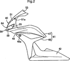
 23 verbundenes Einlasssystem 34 weist einen Luftfilter 35, der von Benzintank 29 bedeckt wird; und zwischen dem Luftfilter 35 und dem Zylinderkopf 23 in jedem Zylinder angeordnete Drosselklappenstutzen 36⋯ auf. Weiterhin weist ein mit der vorderen Seitenfläche des Zylinderkopfs 22 verbundenes Abgassystem 37 einen Auspufftopf 38 am hinteren Ende davon auf, wobei der Auspufftopf 38 über dem Hinterrad WR angeordnet ist.One with the side surface of the rear portion of the cylinder head 23 connected inlet system 34 has an air filter 35 from the gas tank 29 is covered; and between the air filter 35 and the cylinder head 23 arranged in each cylinder throttle body 36 ⋯ up. Furthermore, one with the front side surface of the cylinder head 22 connected exhaust system 37 a muffler 38 at the back end of it, with the muffler 38 is arranged above the rear wheel WR.

Es wird nun auf 2 und 3 Bezug genommen. Der Lenkkopf 12 im vorderen Endbereich des Gehäuserahmens F wird von vorne durch eine Frontverkleidung 40 abgedeckt, die direkt über dem Vorderrad WF angeordnet ist, ein rechtes und linkes Paar von Mittenverkleidungen (Center Cowls) 41⋯, die den vorderen Bereich des Gehäuserahmens F und einen Teil des Verbrennungsmotors E in seitlicher Richtung abdecken, sind durchgängig auf der rechten und der linken Seite der Frontverkleidung 40 vorgesehen. Ein rechtes und ein linkes Paar von unteren Verkleidungen 42⋯, die den unteren Bereich des Verbrennungsmotors E seitlich und nach unten abdecken und gleichzeitig miteinander verbunden sind, sind durchgängig an den hinteren unteren Bereichen der Mittenverkleidungen 41⋯ vorgesehen. Darüber hinaus sind ein rechtes und linkes Paar von Seitenabdeckungen 43⋯, die den hinteren unteren Bereich des Benzintanks 29 von beiden Seiten bedecken, zwischen dem Benzintank 29 und dem Vordersitz zum Fahren 30 vorgesehen. Eine hintere Verkleidung 44, die nach hinten nach oben verläuft, ist durchgängig am hinteren Bereich von beiden seitlichen Abdeckungen 43⋯ vorgesehen.It will be up now 2 and 3 Referenced. The steering head 12 in the front end region of the housing frame F is from the front by a front panel 40 covered directly above the front wheel WF, a right and left pair of center cowls 41 ⋯, which cover the front portion of the housing frame F and a part of the internal combustion engine E in the lateral direction, are consistently on the right and the left Side of the front panel 40 intended. A right and a left pair of lower panels 42 ⋯, which cover the lower portion of the engine E laterally and downwardly and at the same time are interconnected, are continuous at the rear lower portions of the center panels 41 ⋯ provided. In addition, there are a right and left pair of side covers 43 ⋯, which is the rear lower portion of the fuel tank 29 cover from both sides, between the gas tank 29 and the front seat to drive 30 intended. A rear panel 44 , which runs backwards, is continuous at the rear of both side covers 43 ⋯ provided.

Darüber hinaus wird ein vorderer Kotflügel 45, der wenigstens einen Teil des Vorderrads WF von oben bedeckt, von der Vordergabel 11 gehalten. Ein hinterer Kotflügel 46, der das Hinterrad WR von hinten oben abdeckt, wird am hinteren Bereich der Sitzschiene 16⋯ gehalten.In addition, a front fender 45 which covers at least a part of the front wheel WF from above, from the front fork 11 held. A rear fender 46 , which covers the rear wheel WR from behind the top, is at the rear of the seat rail 16 ⋯ held.

Die Mittenabdeckung 41 weist auf: eine obere Verkleidung (Upper Cowl) 47, die durchgängig am hinteren Bereich der Frontverkleidung 40 vorgesehen ist und den vorderen Bereich des Gehäuserahmens F seitlich abdeckt; und eine untere Verkleidung 48 (Lower Cowl), die durchgängig am hinteren Bereich der oberen Verkleidung 47 vorgesehen ist. Die untere Verkleidung 48 ist ausgebildet, dass sie auf diese Weise den Zylinderkopf 23 und die Zylinderkopfabdeckung 24 des Motorgehäuses 19; einen Teil des Abgassystems 37 des Verbrennungsmotors E; und einen Teil des Kühlers 33 seitlich abdeckt. Darüber hinaus ist, um den Fahrtwind zur Seite des Kühlers 33 zu leiten, ein den oberen Bereich des Kühlers 33 in der Seitenansicht schneidender Öffnungsbereich 49 zwischen der oberen Verkleidung 47 und dem vorderen Bereich der unteren Verkleidung 48 ausgebildet, um so nach vorne und hinten zu verlaufen. Ein Blinkerbefestigungsaufnahme 48a ist ausgebildet, um einen Blinker 50 (siehe 1) am vorderen Bereich der unteren Verkleidung 48 anzubringen.The center cover 41 indicates: an upper cowl 47 that are continuous at the rear of the front panel 40 is provided and covers the front portion of the housing frame F side; and a lower panel 48 (Lower Cowl), which is continuous at the rear of the upper fairing 47 is provided. The lower panel 48 is designed to be the cylinder head in this way 23 and the cylinder head cover 24 of the motor housing 19 ; a part of the exhaust system 37 the internal combustion engine E; and a part of the radiator 33 covers on the side. In addition, the wind to the side of the radiator 33 to direct one the upper area of the radiator 33 in the side view cutting opening area 49 between the upper panel 47 and the front area of the lower fairing 48 designed to run forwards and backwards. A turn signal attachment 48a is designed to be a turn signal 50 (please refer 1 ) at the front of the lower fairing 48 to install.

Es wird auf 4 Bezug genommen. Die Frontverkleidung 40 weist auf eine äußere Verkleidung 51, die im Querschnitt in einer annähernden U-Form ausgebildet ist; und eine innere Verkleidung 52, die an der unteren Innenseite der äußeren Verkleidung 51 angebracht ist. Eine Windschutzscheibe 53 ist am oberen Mittenbereich der äußeren Verkleidung 51 angebracht. Ein rechtes und linkes Paar von Spiegelbefestigungsaufnahmen 51a⋯ sind auf der äußeren Verkleidung 51 zur Anbringung der Rückspiegel 54⋯ (siehe 1) angebracht, die an der rechten und an der linken Seite der Windschutzscheibe 53 angeordnet sind.It will open 4 Referenced. The front panel 40 indicates an outer lining 51 formed in cross section in an approximate U-shape; and an inner panel 52 placed on the lower inside of the outer panel 51 is appropriate. A windshield 53 is at the upper center area of the outer panel 51 appropriate. A right and left pair of mirror mount receptacles 51a ⋯ are on the outer panel 51 for attaching the rearview mirror 54 ⋯ (see 1 ) attached to the right and left side of the windshield 53 are arranged.

In der Vorderverkleidung 40 ist ein Öffnungsbereich 55, der sich in Richtung der Fahrzeugbreite erstreckt, am vorderen unteren Bereich der äußeren Verkleidung 51 vorgesehen, und ein Gehäuse 56 zur Montage eines Frontscheinwerfers ist an der bestimmten Position am Öffnungsbereich 55 angeordnet.In the front panel 40 is an opening area 55 extending in the vehicle width direction at the front lower portion of the outer fairing 51 provided, and a housing 56 for mounting a headlight is at the specific position at the opening area 55 arranged.

Es wird weiterhin auf 5 Bezug genommen. Das Gehäuse 56 zur Montage des Frontscheinwerfers weist jeweils ein rechtes und linkes Paar von Lampengehäusen 57, 57, die in einer nach vorne geöffneten Schalenform ausgebildet sind; einen zylindrischen Verbindungsbereich 58, der zwischen diesen Lampengehäusen 57⋯ eine Verbindung herstellt; Linsen 59, 59, die am vorderen Bereich eines jeden Lampengehäuses 57⋯ angebracht sind, um auf diese Weise jeweils die offenen Enden der Lampengehäuse 57⋯ abzudecken; Reflektoren 60, 60, die in dem Paar von Lampengehäusen 57⋯ enthalten sind, und Linsen 59⋯ auf; eine Leuchtenbaugruppe (nicht dargestellt), die im Mittenbereich der Reflektoren 60⋯ angeordnet ist. Das Montagegehäuse des Frontscheinwerfers ist an der äußeren Verkleidung 51 der Frontverkleidung 40 angebracht, um auf diese Weise im Öffnungsbereich 55 eingesteckt zu sein.It will continue on 5 Referenced. The housing 56 for mounting the headlight, each has a right and left pair of lamp housings 57 . 57 formed in a forwardly open shell shape; a cylindrical connection area 58 that between these lamp housings 57 ⋯ establishes a connection; lenses 59 . 59 at the front of each lamp housing 57 ⋯ are attached to each other in this way the open ends of the lamp housing 57 ⋯ cover; reflectors 60 . 60 that in the pair of lamp housings 57 ⋯ are included, and lenses 59 ⋯ open; a light assembly (not shown) in the center region of the reflectors 60 ⋯ is arranged. The mounting housing of the headlight is on the outer panel 51 the front panel 40 attached to this way in the opening area 55 to be plugged in.

Es wird weiterhin auf 6 Bezug genommen. Ein zylindrischer Fahrtwind-Einlasszylinder 62, der einen zur Vorderseite geöffneten Fahrtwindeinlass 61 bildet, ist so angeordnet, dass er den hinteren Endbereich davon mit dem vorderen Endbereich des Verbindungsbereichs 58 zwischen beiden Linsen 59⋯ verbindet. Ein Lüftungsschlitz 63, der als Vogelabwehr eine Gitterform aufweist, ist eingefügt und im hinteren Bereich des Fahrtwind-Einlasszylinders 62 befestigt.It will continue on 6 Referenced. A cylindrical airstream inlet cylinder 62 , which has a windward inlet open to the front 61 is formed so that it has the rear end portion thereof with the front end portion of the connecting portion 58 between both lenses 59 ⋯ connects. A ventilation slot 63 , which has a lattice shape as a bird repellent, is inserted and in the rear of the headwind intake cylinder 62 attached.

Anders ausgedrückt, die Frontscheinwerfer
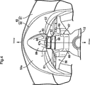
 64, 64 sind an der bestimmten Position an der rechten und linken Seite des vorderen Bereichs der Frontverkleidung 40 angeordnet. Ein Fahrtwindeinlass 61 ist am vorderen Endbereich der Frontverkleidung 40 vorgesehen, um auf diese Weise zwischen den Frontscheinwerfern 64⋯ angeordnet zu sein.In other words, the headlights 64 . 64 are at the specified position on the right and left sides of the front portion of the front panel 40 arranged. A wind intake 61 is at the front end area of the front panel 40 provided to this way between the headlights 64 ⋯ to be arranged.

In 7 besteht ein Teil der Frontverkleidung aus der unteren Platte 52a der Frontverkleidung 40, um auf diese Weise von der Vorderkante der äußeren Verkleidung 51 nach hinten zu verlaufen, und ein Lufteinlasskanal 66, der den Fahrtwind zur Seite des Verbrennungsmotors E leitet, ist zwischen der unteren Platte 52a und der Oberseite des vorderen Kotflügels 45 ausgebildet.In 7 Part of the front panel consists of the lower panel 52a the front panel 40 order this way from the leading edge of the outer fairing 51 to run backwards, and an air intake duct 66 that conducts the airstream to the side of the engine E is between the lower plate 52a and the top of the front fender 45 educated.

Eine einzelne Lufteinlassführung 67 ist über dem vorderen Kotflügel 45 angeordnet, um die vom am vorderen Endbereich der Frontverkleidung 40 vorgesehenen Fahrtwindeinlass 61 geführte Luft dem Luftfilter 35 des Einlasssystems 34 dem Verbrennungsmotor E zuzuführen. Wenigstens ein Teil der Lufteinlassführung 67, die den vorderen Bereich der Lufteinlassführung 67 in der vorliegenden Ausführungsform bildet, ist in der Frontverkleidung 40 enthalten.A single air inlet duct 67 is over the front fender 45 arranged at the front end of the front panel 40 provided Fahrtwindeinlass 61 guided air to the air filter 35 of the intake system 34 to supply the internal combustion engine E. At least part of the air inlet guide 67 covering the front area of the air inlet guide 67 in the present embodiment is in the front panel 40 contain.

Es wird weiterhin auf 8 und 9 Bezug genommen. Die Lufteinlassführung 67 besteht aus einem rechten und linken Paar von Führungshalbkörpern 68, 69, die zusammengefügt werden und einen rechteckigen Querschnitt aufweisen. Darüber hinaus ist eine mit dem hinteren Ende des zylindrischen Verbindungsbereichs 58 verbundene Einlassöffnung im Montagegehäuse 56 des Frontscheinwerfers am vorderen Endbereich der Lufteinlassführung 67 ausgebildet. Ein rechtes und ein linkes Paar von Auslassöffnungen 72, 72, die durch eine Trennwand 71 getrennt sind, um auf diese Weise den Innenraum der Lufteinlassführung 67 in einen rechten und linken Bereich zu unterteilen, ist am hinteren Bereich der Lufteinlassführung 67 ausgebildet. Ein Luftkanal 73 ist in der Lufteinlassführung 67 ausgebildet, so dass die von der Einlassöffnung 70 zu beiden Auslassöffnungen 72⋯ geleitete Luft fließen kann.It will continue on 8th and 9 Referenced. The air inlet guide 67 consists of a right and left pair of guide half-bodies 68 . 69 , which are joined together and have a rectangular cross-section. In addition, one is with the rear end of the cylindrical connection area 58 connected inlet opening in the mounting housing 56 of the headlight at the front end portion of the air inlet guide 67 educated. A right and a left pair of outlet openings 72 . 72 passing through a partition 71 are separated in this way the interior of the air inlet guide 67 to divide into a right and left area is at the rear of the air inlet guide 67 educated. An air duct 73 is in the air intake duct 67 formed so that the from the inlet opening 70 to both outlet openings 72 ⋯ conducted air can flow.

Darüber hinaus sind einen rechtes und linkes Paar von Resonanzkammern 74, 74 am vorderen Bereich in der Lufteinlassführung 67 ausgebildet, um auf diese Weise vom Luftkanal 73 getrennt zu sein. Die Resonanzkammern 74⋯ stehen mit dem Luftkanal 73 über das Verbindungsrohr 75⋯ in Verbindung.In addition, there are a right and left pair of resonance chambers 74 . 74 at the front area in the air inlet guide 67 designed to be that way from the air duct 73 to be separated. The resonance chambers 74 ⋯ stand with the air duct 73 over the connecting pipe 75 ⋯ in connection.

Hier weist der Lenkkopf 12 im Gehäuserahmen F einen zylindrischen Haltebereich 12a, der die Vordergabel 11 lenkbar hält, und gleichzeitig ein rechtes und linkes Paar von Kanälen 76, 76 auf, die auf der rechten und der linken Seite des zylindrischen Haltebereichs 12a angeordnet sind. Der hintere Endbereich der Lufteinlassführung 67 ist mit dem Lenkkopf 12 verbunden, um auf diese Weise mit der Auslassöffnung 72⋯ am hinteren Endbereich der Lufteinlassführung 67 mit den Kanälen 76⋯ auf der rechten und linken Seite des zylindrischen Haltebereichs 12a in Verbindung zu stehen.Here is the steering head 12 in the housing frame F a cylindrical holding area 12a who has the front fork 11 steerable, and at the same time one right and left pair of channels 76 . 76 on, on the right and the left side of the cylindrical holding area 12a are arranged. The rear end portion of the air inlet guide 67 is with the steering head 12 connected to this way with the outlet opening 72 ⋯ at the rear end of the air inlet guide 67 with the channels 76 ⋯ on the right and left side of the cylindrical holding area 12a to communicate.

Darüber hinaus stehen die Kanäle 76⋯ des Lenkkopfs 12 mit zwei Luftkanälen 78, 78 rechts und links in Verbindung, die in einem Verbindungsstück 77 enthalten sind, das am Lenkkopf 12 von hinten angebracht ist, wie in 5 und 6 dargestellt. Darüber hinaus ist ein in 6 dargestelltes Lufteinlasselement 79 mit dem Verbindungsstück 77 verbunden. Das Lufteinlasselement 79 ist am Luftfilter 35 des Einlasssystems 34 angebracht. Die beiden Luftkanäle 78⋯ des Verbindungsstücks 77 stehen jeweils mit zwei im Lufteinlasselement 79 enthaltenen Einlasskanälen 80, 80 in Verbindung.Beyond that are the channels 76 ⋯ of the steering head 12 with two air channels 78 . 78 Connected right and left in a connector 77 are included, the steering head 12 attached from behind, as in 5 and 6 shown. In addition, an in 6 illustrated air inlet element 79 with the connector 77 connected. The air inlet element 79 is at the air filter 35 of the intake system 34 appropriate. The two air channels 78 ⋯ of the connector 77 each with two in the air inlet element 79 contained inlet channels 80 . 80 in connection.

Vier Verankerungsbefestigungsaugen 81, 81⋯ stehen auf der Oberseite der Lufteinlassführung 67 hervor. Eine Verankerung 82 für ein Messinstrument ist auf diesem Verankerungsbefestigungsaugen 81, 81⋯ befestigt, um ein Messinstrument anzubringen, das nicht dargestellt ist. Die Verankerung 82 für ein Messinstrument weist ein rechtes und linkes Paar von Hohlbereichen 82a, 82a auf. Die Hohlbereiche 82a⋯ sind in einem rechten und linken Paar von Einsatzöffnungen 83, 83 eingesetzt, die auf der Oberseite der Lufteinlassführung 67 hinter den Resonanzkammern 74⋯ vorgesehen sind und mit dem Luftkanal 73 in der Lufteinlassführung 76 in Verbindung stehen. Dann fungieren die Hohlbereiche 82a⋯ als Luftreservoir. Wenn die Drosselklappen des Verbrennungsmotors E schnell geöffnet werden etc., wird die Luft in den Hohlbereichen 82a⋯ zeitweise dem Luftkanal 73 zugeführt, was den negativen Druckwechsel im Luftkanal 73 erleichtert.Four anchoring fastening eyes 81 . 81 ⋯ stand on the top of the air inlet guide 67 out. An anchorage 82 for a meter is on this mooring fixing eyes 81 . 81 ⋯ attached to attach a meter, which is not shown. The anchorage 82 for a measuring instrument has a right and left pair of hollow areas 82a . 82a on. The hollow areas 82a ⋯ are in a right and left pair of insertion holes 83 . 83 inserted on top of the air inlet guide 67 behind the resonance chambers 74 ⋯ are provided and with the air duct 73 in the air inlet guide 76 keep in touch. Then the hollow areas act 82a ⋯ as an air reservoir. When the throttles of the engine E are opened quickly, etc., the air in the cavities 82a ⋯ temporarily the air duct 73 fed, indicating the negative pressure change in the air duct 73 facilitated.

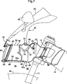
Dann ist wenigstens ein Teil der Lufteinlassführung 67, die den vorderen Bereich der Lufteinlassführung 67 in der vorliegenden Ausführungsform bildet, in der Frontverkleidung 40 im Mittenbereich in Richtung der Fahrzeugbreite enthalten. Wie in 7 dargestellt, ist ein hinterer Lufteinlasskanal 85, der von hinten mit dem Lufteinlasskanal 66 verbunden ist, zwischen dem unteren Blech 52a der Frontverkleidung 40 und der Oberseite des vorderen Kotflügels 45 zwischen der Lufteinlassführung 67 und der Oberseite der Frontverkleidung 45 ausgebildet.Then at least part of the air inlet guide 67 covering the front area of the air inlet guide 67 forms in the present embodiment, in the front panel 40 in the middle area in the direction of the vehicle width included. As in 7 is shown, is a rear air inlet duct 85 from the rear with the air intake duct 66 is connected between the lower plate 52a the front panel 40 and the top of the front fender 45 between the air inlet guide 67 and the top of the front panel 45 educated.

Weiterhin stehen Luftführungsbereiche 86, 87, 88, die den Fahrtwind zur Seite des Kühlers 33 leiten, an wenigstens einem Teil der Lufteinlassführung 67 hervor, die in der vorliegenden Ausführungsform die Unterseite der untersten Bodenwand 67a ist.Furthermore, there are air ducts 86 . 87 . 88 , the wind to the side of the radiator 33 lead, at least part of the air inlet guide 67 in the present embodiment, the underside of the bottom bottom wall 67a is.

Die Unterseite der untersten Bodenwand 67a der Lufteinlassführung 67 ist als flache Form ausgebildet. Zum Beispiel sind drei Luftführungsbereiche 86, 87, 88, die sich in Richtung der Fahrzeugbreite erstrecken, integral ausgebildet, um an einer Unterseite davon nach unten hervorzustehen.The underside of the bottom bottom wall 67a the air inlet guide 67 is designed as a flat shape. For example, there are three air duct areas 86 . 87 . 88 extending in the vehicle width direction, integrally formed to protrude downwardly from an underside thereof.

Die unterste Bodenwand 67a der Lufteinlassführung 67 ist von hinten in der Nähe des Mittenbereichs in Richtung der Fahrzeugbreite der unteren Platte 52a der Frontverkleidung 40 angeordnet. Der vorderste Luftführungsbereich 86 der Vielzahl von Luftführungsbereichen 86, 87, 88 ist integral am vorderen Endbereich der Unterseite der untersten Bodenwand 67a ausgebildet.The lowest bottom wall 67a the air inlet guide 67 is from behind in the vicinity of the center region in the direction of the vehicle width of the lower plate 52a the front panel 40 arranged. The foremost air duct area 86 the variety of air ducts 86 . 87 . 88 is integral with the front end portion of the underside of the bottom bottom wall 67a educated.

Darüber hinaus ist die Unterseite der untersten Bodenwand 67a als durchgängig geneigte Fläche ausgebildet, um auf diese Weise allmählich im Verlauf nach hinten abgesenkt zu werden. Die Luftführungsbereiche 86, 87, 88 sind integral ausgebildet, um auf diese Weise nach vorne und hinten an der Unterseite der untersten Bodenwand 67a beanstandet zu sein. Der hinterste Luftführungsbereich 88 der Vielzahl von Luftführungsbereichen 86, 87, 88 ist integral am hintersten Ende der Unterseite der untersten Bodenwand 67a ausgebildet.In addition, the bottom is the bottom bottom wall 67a formed as a continuous inclined surface so as to be gradually lowered in the course of the backward. The air ducts 86 . 87 . 88 are integrally formed so as to be forward and backward at the bottom of the lowermost bottom wall 67a to be criticized. The rearmost airflow area 88 the variety of air ducts 86 . 87 . 88 is integral at the rearmost end of the underside of the bottom bottom wall 67a educated.

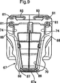
Hier ist die unterste Bodenwand 67a der Lufteinlassführung 67 so ausgebildet, dass sie sich allmählich in Richtung der Fahrzeugbreite im Verlauf nach hinten verbreitert. Die Breiten in Richtung der Fahrzeugbreite der Vielzahl von Luftführungsbereichen 86, 87, 88, die so angeordnet sind, dass sie vorne und hinten beanstandet sind, sind gemäß der Breite der untersten Bodenwand 67a voneinander verschieden festgelegt.Here is the bottom wall 67a the air inlet guide 67 designed so that it widened gradually towards the vehicle width in the course to the rear. The widths in the vehicle width direction of the plurality of air guide areas 86 . 87 . 88 , which are arranged so that they are spaced front and rear, are according to the width of the bottom bottom wall 67a set differently from each other.

Anders ausgedrückt, aufgrund der Tatsache, dass die unterste Bodenwand 67a so ausgebildet ist, dass sie sich in Richtung der Fahrzeugbreite allmählich im Verlauf nach hinten verbreitert, werden die Breiten in Richtung der Fahrzeugbreite der Luftführungsbereich 86, 87, 88 breiter festgelegt, je weiter der Luftführungsbereich nach hinten angeordnet ist. Dementsprechend wird die Breite der geraden Linie L, L, die beide Enden der Luftführungsbereiche 86, 87, 88 in Richtung der Fahrzeugbreite verbindet, im Verlauf nach hinten breiter, wie in 4 dargestellt.In other words, due to the fact that the bottom bottom wall 67a is formed so that it widens gradually in the direction of the vehicle width in the course of the rear, the widths in the direction of the vehicle width of the air duct area 86 . 87 . 88 set wider, the farther the air duct is arranged to the rear. Accordingly, the width of the straight line L, L becomes both ends of the air guide portions 86 . 87 . 88 connects in the direction of the vehicle width, wider in the course to the rear, as in 4 shown.

Weiterhin ist die Nut 89 an der Unterseite des Mittenbereichs in Richtung der Fahrzeugbreite der unteren Platte 52a der Frontverkleidung 40 ausgebildet, um auf diese Weise nach oben konkav zu verlaufen und auf diese Weise nach vorne und hinten zu verlaufen. Die Luftführungsbereiche 86, 87, 88 sind in der Vorderansicht des Fahrzeugs in der maximalen Breite der Nut 89 angeordnet, wie in 3 dargestellt.Furthermore, the groove 89 at the bottom of the center region in the direction of the vehicle width of the lower plate 52a the front panel 40 formed so as to be concave upwards and in this way to extend forwards and backwards. The air ducts 86 . 87 . 88 are in the front view of the vehicle in the maximum width of the groove 89 arranged as in 3 shown.

Darüber hinaus, wie in 4 dargestellt, ist ein konkaver Bereich 90, der in der Draufsicht konkav in einer V-Form nach vorne verläuft, am hinteren Ende des Mittenbereichs in Richtung der Fahrzeugbreite der unteren Platte 52a der Frontverkleidung 40 ausgebildet. Die Luftführungsbereiche 86, 87, 88 sind in der Draufsicht im konkaven Bereich 90 angeordnet. In addition, as in 4 is a concave area 90 which is concave forward in plan view in a V-shape, at the rear end of the center portion in the vehicle width direction of the lower plate 52a the front panel 40 educated. The air ducts 86 . 87 . 88 are in the plan view in the concave area 90 arranged.

Als Nächstes werden die Funktionen der vorliegenden Ausführungsform erläutert. Die Lufteinlassführung 67 ist so über dem vorderen Kotflügel 45 angeordnet, dass wenigstens ein Teil davon in der Frontverkleidung 40 enthalten ist, um die von dem am vorderen Endbereich der Frontverkleidung 40 vorgesehenen Fahrtwindeinlass 61 geführte Luft dem Einlasssystem 34 des Verbrennungsmotors E zuzuführen (ist über dem vorderen Kotflügel 45 angeordnet). Der hintere Lufteinlasskanal 85, der von hinten mit dem zwischen der unteren Platte 52a der Frontverkleidung 40 und der Oberseite des vorderen Kotflügels 45 ausgebildeten Lufteinlasskanal 66 verbunden ist, ist zwischen der Lufteinlassführung 67 und dem vorderen Kotflüge 45 ausgebildet. Die Luftführungsbereiche 86, 87, 88, die den Fahrtwind zur Seite eines Kühlers 33 führen, stehen an der Unterseite der untersten Bodenwand 67a der Lufteinlassführung 67 hervor. Dementsprechend wird der Fahrtwind, der durch den Lufteinlasskanal 66 und den hinteren Lufteinlasskanal 85 fließt, zur Seite des Kühler 33 geführt, was die Kühlleistung des Kühlers 33 verbessern kann. Darüber hinaus, da die Frontverkleidung 40 nicht mit Luftführungsbereichen vorgesehen ist, wird die Frontverkleidung 40 nicht durch die Luftführungsbereiche nach unten ausgebuchtet. Der Luftwiderstand kann reduziert werden, indem die Position der Frontverkleidung 40 abgesenkt wird.Next, the functions of the present embodiment will be explained. The air inlet guide 67 is so over the front fender 45 arranged that at least part of it in the front panel 40 included is that of the front end portion of the front bezel 40 provided Fahrtwindeinlass 61 guided air to the intake system 34 of the internal combustion engine E (is above the front fender 45 arranged). The rear air intake duct 85 from the back with the between the lower plate 52a the front panel 40 and the top of the front fender 45 trained air intake duct 66 is connected between the air inlet guide 67 and the front droppings 45 educated. The air ducts 86 . 87 . 88 putting the wind to the side of a radiator 33 lead, stand at the bottom of the bottom bottom wall 67a the air inlet guide 67 out. Accordingly, the airstream passing through the air intake duct 66 and the rear air intake duct 85 flows, to the side of the radiator 33 led, what the cooling capacity of the radiator 33 can improve. In addition, because the front panel 40 is not provided with air ducts, the front panel 40 not bulged down through the air ducts. Air resistance can be reduced by adjusting the position of the front fairing 40 is lowered.

Darüber hinaus ist wenigstens ein Teil der einzelnen Lufteinlassführung 67 mit einer rechtwinkligen Querschnittsform in der Frontverkleidung 40 an einer Mittenposition in Richtung der Fahrzeugbreite enthalten. Die in Richtung der Fahrzeugbreite verlaufenden Luftführungsbereiche 86, 87, 88 sind integral an der flachen Unterseite der untersten Bodenwand 67a der Lufteinlassführung 67 ausgebildet, um auf diese Weise nach unten hervorzustehen. Dementsprechend sind die Luftführungsbereiche 86, 87, 88 so ausgebildet, dass sie in Richtung der Fahrzeugbreite breit sind, um deren Fläche zu erhöhen, was den Lufteinlasseffekt verbessern kann.In addition, at least part of the individual air inlet guide 67 with a rectangular cross-sectional shape in the front panel 40 at a center position in the vehicle width direction. The running in the direction of the vehicle width air ducts 86 . 87 . 88 are integral to the flat underside of the bottom bottom wall 67a the air inlet guide 67 designed to stand down in this way. Accordingly, the air duct areas 86 . 87 . 88 formed so as to be wide in the vehicle width direction to increase the area thereof, which can improve the air intake effect.

Darüber hinaus ist die unterste Bodenwand 67a der Lufteinlassführung 67 von hinten in der Nähe des Mittenbereichs in Richtung der Fahrzeugbreite des unteren Blechs 52a der Frontverkleidung 40 angeordnet, und der Luftführungsbereich 86 ist integral am vorderen Endbereich der Unterseite der untersten Bodenwand 67a ausgebildet. Dementsprechend kann der Luftführungsbereich 86 direkt hinter der unteren Platte 52a den entlang der Unterseite der unteren Platten der Frontverkleidung 40 fließenden Fahrtwind zur Seite des Kühler 33 sicher führen.In addition, the bottom floor wall is 67a the air inlet guide 67 from the rear in the vicinity of the center region in the direction of the vehicle width of the lower plate 52a the front panel 40 arranged, and the air duct area 86 is integral with the front end portion of the underside of the bottom bottom wall 67a educated. Accordingly, the air guide area 86 directly behind the lower plate 52a along the bottom of the lower panels of the front panel 40 flowing wind to the side of the radiator 33 lead safely.

Darüber hinaus ist die Unterseite der untersten Bodenwand 67a als durchgängig geneigte Fläche ausgebildet, um auf diese Weise allmählich im Verlauf nach hinten abgesenkt zu werden. Dementsprechend kann die Unterseite der untersten Bodenwand 67a den Fahrtwind zur Seite des Kühlers 33 sicher leiten.In addition, the bottom is the bottom bottom wall 67a formed as a continuous inclined surface so as to be gradually lowered in the course of the backward. Accordingly, the bottom of the bottom bottom wall 67a the airstream to the side of the radiator 33 guide safely.

Darüber hinaus ist die Vielzahl der (zum Beispiel drei) Luftführungsbereiche 86, 87, 88 integral ausgebildet, um auf diese Weise nach vorne und hinten an der Unterseite der untersten Bodenwand 67a beabstandet zu sein. Dementsprechend kann ein beliebiger der Vielzahl der Luftführungsbereiche 86, 87, 88 den Fahrtwind führen, selbst wenn der vordere Bereich des Motorrads dazu neigt, aufgrund der hinteren Beladung bei der Beschleunigung des Motorrads angehoben zu werden. Der Lufteinlasseffekt zur Seite des Kühlers 33 kann unabhängig vom Fahrzustand des Motorrades erwartet werden.In addition, the plurality of (for example, three) air ducts 86 . 87 . 88 integrally formed so as to be forward and backward at the bottom of the bottom bottom wall 67a to be spaced. Accordingly, any one of the plurality of air guide portions 86 . 87 . 88 lead the wind, even if the front area of the motorcycle tends to be raised due to the rear loading when accelerating the motorcycle. The air intake effect to the side of the radiator 33 can be expected regardless of the driving condition of the motorcycle.

Darüber hinaus ist der hinterste Luftführungsbereich 88 der Vielzahl von Luftführungsbereichen 86, 87, 88 integral am hintersten Ende der Unterseite der untersten Bodenwand 67a ausgebildet. Dementsprechend kann der hinterste Luftführungsbereich 88 den nach hinten fließenden Fahrtwind entlang der geneigten Unterseite der untersten Bodenwand 67a zur Seite des Kühlers 33 führen, wobei der Fluss von der Unterfläche der untersten Bodenwand 67a abgelenkt wird, was die Lufteinlassleistung verbessern kann.In addition, the rearmost air duct area 88 the variety of air ducts 86 . 87 . 88 integral at the rearmost end of the underside of the bottom bottom wall 67a educated. Accordingly, the rearmost air duct area 88 the backward flowing wind along the inclined underside of the bottom bottom wall 67a to the side of the radiator 33 Lead, with the flow from the lower surface of the bottom bottom wall 67a is deflected, which can improve the air intake performance.

Darüber hinaus ist wenigstens die unterste Bodenwand 67a der Lufteinlassführung 67 so ausgebildet, dass sie sich allmählich in Richtung der Fahrzeugbreite nach hinten verbreitert, wobei die Breiten in Richtung der Fahrzeugbreite der Vielzahl der Luftführungsbereiche 86, 87, 88 nach vorne und hinten gemäß der Breite der untersten Bodenwand 67a voneinander verschieden festgelegt werden. Dementsprechend können die hinteren Luftführungsbereiche 87, 88 den durch beide Seiten des vorderen Luftführungsbereichs 86 fließenden Fahrtwind führen. Der hinterste Luftführungsbereich 88 kann den über beide Seiten des Luftführungsbereichs 87 fließenden Fahrtwind sicher zur Seite des Kühlers 33 führen.In addition, at least the bottom bottom wall 67a the air inlet guide 67 is formed so that it widened gradually in the direction of the vehicle width to the rear, the widths in the direction of the vehicle width of the plurality of air ducts 86 . 87 . 88 forward and backward according to the width of the lowest bottom wall 67a be set differently from each other. Accordingly, the rear air ducts can 87 . 88 through both sides of the front air ducting area 86 lead a flowing wind. The rearmost airflow area 88 Can the over both sides of the air duct 87 flowing wind safely to the side of the radiator 33 to lead.

Darüber hinaus ist die Nut 89 an der Unterseite des Mittenbereichs in Richtung der Fahrzeugbreite der unteren Platte 52a der Frontverkleidung 40 ausgebildet, um konkav nach oben zu verlaufen, und nach vorne und hinten zu verlaufen, wobei die Luftführungsbereiche 86, 87, 88 in der Vorderansicht in der maximalen Breite der Nut 89 des Fahrzeugs angeordnet sind. Dementsprechend kann der Fahrtwind zur Seite der Luftführungsbereiche 86, 87, 88 mittels der Nut 89 der Unterseite der unteren Platte 52a geführt werden, was den Lufteinlasseffekt verbessern kann.In addition, the groove 89 at the bottom of the center region in the direction of the vehicle width of the lower plate 52a the front panel 40 designed to be concave upwards and to run forwards and backwards, with the air ducting areas 86 . 87 . 88 in the front view in the maximum width of the groove 89 of the vehicle are arranged. Accordingly, the airstream to the side of the air duct areas 86 . 87 . 88 by means of the groove 89 the bottom of the lower plate 52a which can improve the air intake effect.

Darüber hinaus ist der konkave Bereich 90, der in der Draufsicht konkav in einer V-Form nach vorne verläuft, am hinteren Ende des Mittenbereichs in Richtung der Fahrzeugbreite der unteren Platte 52a der Frontverkleidung 40 ausgebildet. Die Luftführungsbereiche 86, 87, 88 sind in der Draufsicht im konkaven Bereich 90 angeordnet.In addition, the concave area 90 which is concave forward in plan view in a V-shape, at the rear end of the center portion in the vehicle width direction of the lower plate 52a the front panel 40 educated. The air ducts 86 . 87 . 88 are in the plan view in the concave area 90 arranged.

Dementsprechend können die Luftführungsbereiche 86, 87, 88 in der Nähe der Frontverkleidung 40 angeordnet werden, und die Luftführungsbereiche 86, 87, 88 können den unter der Frontverkleidung 40 durchfließenden Fahrtwind zur vorgelagerten Seite der Flussrichtung leiten.Accordingly, the air ducts 86 . 87 . 88 near the front panel 40 be arranged, and the air duct areas 86 . 87 . 88 Can the under the front panel 40 flowing through the wind to the upstream side of the flow direction.

Wie oben ausgeführt, wurde die Ausführungsform der vorliegenden Erfindung erläutert. Die vorliegende Erfindung ist nicht auf die oben ausgeführte Ausführungsform beschränkt. Es können verschiedene Änderungen angewendet werden, ohne vom Umfang der vorliegenden Erfindung abzuweichen.As stated above, the embodiment of the present invention has been explained. The present invention is not limited to the above embodiment. Various changes may be made without departing from the scope of the present invention.

Zum Beispiel wird der Wärmetauscher als Kühler 33 in der oben erläuterten Ausführungsform erläutert. Die vorliegende Erfindung kann jedoch auch in dem Fall ausgeübt werden, dass ein Ölkühler als Wärmetauscher erläutert wird. For example, the heat exchanger is used as a cooler 33 explained in the above-explained embodiment. However, the present invention can be practiced also in the case that an oil cooler is explained as a heat exchanger.

BezugszeichenlisteLIST OF REFERENCE NUMBERS

1111
Vordergabelfront fork
1212
LenkkopfCaster
1919
Motorgehäusemotor housing
3333
Kühler der ein Wärmetauscher istRadiator that is a heat exchanger
3434
Einlasssystemintake system
4040
Frontverkleidungfront panel
4545
Vorderer KotflügelFront fender
52a52a
Untere PlatteLower plate
6161
FahrtwindeinlassWind inlet
6666
LufteinlasskanalAir inlet duct
6767
LufteinlassführungAir inlet guide
67a67a
Unterste Bodenwand einer LufteinlassführungBottom bottom wall of an air inlet guide
8585
Hinterer LufteinlasskanalRear air intake duct
86, 87, 8886, 87, 88
LuftführungsbereichAir management
8989
Nutgroove
9090
Konkaver BereichConcave area
Ee
Verbrennungsmotorinternal combustion engine
FF
Gehäuserahmenhousing frame
WFWF
Vorderradfront

ZITATE ENTHALTEN IN DER BESCHREIBUNG QUOTES INCLUDE IN THE DESCRIPTION

Diese Liste der vom Anmelder aufgeführten Dokumente wurde automatisiert erzeugt und ist ausschließlich zur besseren Information des Lesers aufgenommen. Die Liste ist nicht Bestandteil der deutschen Patent- bzw. Gebrauchsmusteranmeldung. Das DPMA übernimmt keinerlei Haftung für etwaige Fehler oder Auslassungen.This list of the documents listed by the applicant has been generated automatically and is included solely for the better information of the reader. The list is not part of the German patent or utility model application. The DPMA assumes no liability for any errors or omissions.

Zitierte PatentliteraturCited patent literature

  • JP 2006-347343 [0003] JP 2006-347343 [0003]

Zitierte Nicht-PatentliteraturCited non-patent literature

  • Seite der Frontverkleidung [0038] Side of the front panel [0038]

Claims (9)

Eine vordere Luftführungsanordnung des Motorrads in einem Motorrad mit einem an einem Gehäuserahmen (F) angebrachten Motorgehäuse (19) eines Verbrennungsmotors (E); einer Vordergabel (11), die lenkbar von einem Lenkkopf (12) am vorderen Endbereich des Gehäuserahmens (F) gehalten wird, und axial ein Vorderrad (WF) und ebenso einen vorderen Kotflügel (45) hält, der wenigstens einen Teil des Vorderrads (WF) von oben abdeckt; einem Wärmetauscher (33), der hinter dem Vorderrad (WF) und vor dem Motorgehäuse (19) angeordnet ist; einem Lufteinlasskanal (66), der den Fahrtwind zur Seite des Verbrennungsmotors (E) führt, und der zwischen einer Oberseite des vorderen Kotflügels (45) und einer unteren Platte (52a) einer Frontverkleidung (40) ausgebildet ist, die den Lenkkopf (12) von vorne abdeckt, und die direkt über dem Vorderrad (WF) angeordnet ist und vom Gehäuserahmen (F) gehalten wird, dadurch gekennzeichnet, dass wenigstens ein Teil einer Lufteinlassführung (67) in der Frontverkleidung (40) enthalten ist, um auf diese Weise die von einem am vorderen Endbereich der Frontverkleidung (40) vorgesehenen Fahrtwindeinlass (61) geführte Luft einem Einlasssystem (34) des Verbrennungsmotors (E) zuzuführen, um auf diese Weise über dem vorderen Kotflügel (45) angeordnet zu sein und auf diese Weise gleichzeitig einen hinteren Lufteinlasskanal (85) zu bilden, der den Lufteinlasskanal (66) von hinten zwischen der Lufteinlassführung (67) und dem vorderen Kotflügel (45) verbindet, wobei Luftführungsbereiche (86, 87, 88), die den Fahrtwind zu Seite des Wärmetauschers (33) führen, wenigstens an der Unterseite der untersten Bodenwand (67a) der Lufteinlassführung (67) hervorstehen.A front air guide assembly of the motorcycle in a motorcycle with a motor housing attached to a housing frame (F) ( 19 ) of an internal combustion engine (E); a front fork ( 11 ), steerable by a steering head ( 12 ) is held at the front end portion of the housing frame (F), and axially a front wheel (WF) and also a front fender ( 45 ) which covers at least a part of the front wheel (WF) from above; a heat exchanger ( 33 ), behind the front wheel (WF) and in front of the motor housing ( 19 ) is arranged; an air intake duct ( 66 ), which leads the airstream to the side of the internal combustion engine (E), and between a top of the front fender ( 45 ) and a lower plate ( 52a ) of a front panel ( 40 ) is formed, which the steering head ( 12 ) and which is located directly above the front wheel (WF) and is held by the housing frame (F), characterized in that at least part of an air inlet guide (W) 67 ) in the front panel ( 40 ) in order in this way, that of one at the front end portion of the front panel ( 40 ) provided Fahrtwindeinlass ( 61 ) guided air to an intake system ( 34 ) of the internal combustion engine (E) in order in this way above the front fender ( 45 ) and in this way at the same time a rear air intake duct ( 85 ) forming the air intake duct ( 66 ) from behind between the air inlet guide ( 67 ) and the front fender ( 45 ), whereby air ducts ( 86 . 87 . 88 ), the wind to the side of the heat exchanger ( 33 ), at least at the bottom of the bottom bottom wall ( 67a ) the air inlet guide ( 67 ) protrude. Vordere Luftführungsanordnung des Motorrads gemäß Anspruch 1, dadurch gekennzeichnet, dass wenigstens ein Teil der einzelnen Lufteinlassführung (67), die eine rechtwinklige Querschnittsform aufweist, in der Frontverkleidung (40) im Mittenbereich in Richtung der Fahrzeugbreite enthalten ist, wobei die Luftführungsbereiche (86, 87, 88), die sich in Richtung der Fahrzeugbreite erstrecken, integral ausgebildet sind, um auf diese Weise an der flachen Unterseite der untersten Bodenwand (67a) der Lufteinlassführung (67) nach unten hervorzustehen.Front air duct assembly of the motorcycle according to claim 1, characterized in that at least a part of the individual air inlet duct ( 67 ), which has a rectangular cross-sectional shape, in the front panel ( 40 ) is included in the center region in the direction of the vehicle width, wherein the air guide areas ( 86 . 87 . 88 ) extending in the vehicle width direction are integrally formed so as to engage the flat underside of the lowermost bottom wall (FIG. 67a ) the air inlet guide ( 67 ) to stand down. Vordere Luftführungsanordnung des Motorrads gemäß Anspruch 2, dadurch gekennzeichnet, dass die unterste Bodenwand (67a) der Lufteinlassführung (67) von hinten in der Nähe des Mittenbereichs in Richtung der Fahrzeugbreite der unteren Platte (52a) der Frontverkleidung (40) angeordnet ist, wobei der Luftführungsbereich (86) wenigstens am vorderen Endbereich der Unterseite der untersten Bodenwand (67a) integral ausgebildet ist.Front air duct assembly of the motorcycle according to claim 2, characterized in that the lowermost bottom wall ( 67a ) the air inlet guide ( 67 ) from behind in the vicinity of the central region in the direction of the vehicle width of the lower plate ( 52a ) of the front panel ( 40 ), wherein the air ducting area ( 86 ) at least at the front end region of the underside of the bottom bottom wall ( 67a ) is integrally formed. Vordere Luftführungsanordnung des Motorrads gemäß Anspruch 2 oder 3, dadurch gekennzeichnet, dass die Unterseite der untersten Bodenwand (67a) als durchgängig geneigte Fläche ausgebildet ist, um auf diese Weise allmählich im Verlauf nach hinten abgesenkt zu werden.Front air duct assembly of the motorcycle according to claim 2 or 3, characterized in that the underside of the lowermost bottom wall ( 67a ) is formed as a continuous inclined surface to be lowered in this way gradually in the course to the rear. Vordere Luftführungsanordnung des Motorrads gemäß Anspruch 4, dadurch gekennzeichnet, dass die Vielzahl der Luftführungsbereiche (86, 87, 88) integral ausgebildet sind, um nach vorne und nach hinten an der Unterseite der untersten Bodenwand (67a) beabstandet zu sein. Front air duct assembly of the motorcycle according to claim 4, characterized in that the plurality of air ducts ( 86 . 87 . 88 ) are integrally formed to forward and backward on the underside of the bottom bottom wall ( 67a ) to be spaced. Vordere Luftführungsanordnung des Motorrads gemäß Anspruch 5, dadurch gekennzeichnet, dass der hinterste Luftführungsbereich (88) der Vielzahl der Luftführungsbereiche (86, 87, 88) integral am hintersten Ende der Unterseite der untersten Bodenwand (67a) ausgebildet ist.Front air duct arrangement of the motorcycle according to claim 5, characterized in that the rearmost air duct area ( 88 ) of the plurality of air ducts ( 86 . 87 . 88 integral with the rearmost end of the underside of the bottom bottom wall ( 67a ) is trained. Vordere Luftführungsanordnung des Motorrads gemäß Anspruch 5 oder 6, dadurch gekennzeichnet, dass wenigstens die unterste Bodenwand (67a) der Lufteinlassführung (67) so ausgebildet ist, dass sie sich auf diese Weise allmählich in Richtung der Fahrzeugbreite im Verlauf nach hinten verbreitert, wobei die Breiten in Richtung der Fahrzeugbreite der Vielzahl der Luftführungsbereiche (86, 87, 88), die so angeordnet sind, dass sie voneinander nach vorne und hinten beabstandet sind, gemäß der Breite der untersten Bodenwand (67a) voneinander verschieden festgelegt werden.Front air duct assembly of the motorcycle according to claim 5 or 6, characterized in that at least the lowermost bottom wall ( 67a ) the air inlet guide ( 67 ) is formed so as to gradually widen in the direction of the vehicle width in the course in the course in the course, the widths in the vehicle width direction of the plurality of air ducts ( 86 . 87 . 88 ) arranged so as to be spaced from each other forward and backward according to the width of the lowermost bottom wall (FIG. 67a ) are set differently from each other. Vordere Luftführungsanordnung des Motorrads gemäß einem der Ansprüche 5 bis 7, dadurch gekennzeichnet, dass eine Nut (89) an der Unterseite des Mittenbereichs in Richtung der Fahrzeugbreite der unteren Platte (52a) der Vorderverkleidung (40) so ausgebildet ist, um auf diese Weise konkav nach oben zu verlaufen und auf diese Weise nach vorne und hinten zu verlaufen, wobei die Luftführungsbereiche (86, 87, 88) in der Vorderansicht des Fahrzeugs in der maximalen Breite der Nut (89) angeordnet sind.Front air duct arrangement of the motorcycle according to one of claims 5 to 7, characterized in that a groove ( 89 ) on the underside of the center region in the direction of the vehicle width of the lower plate ( 52a ) of the front panel ( 40 ) is configured so as to be concave upwards and in this way to extend forwards and backwards, wherein the air guiding areas ( 86 . 87 . 88 ) in the front view of the vehicle in the maximum width of the groove ( 89 ) are arranged. Vordere Luftführungsanordnung des Motorrads gemäß einem der Ansprüche 5 bis 8, dadurch gekennzeichnet, dass ein konkaver Bereich (90), der in der Draufsicht in einer V-Form nach vorne konkav verlaufend ausgebildet ist, am hinteren Ende des Mittenbereichs in Richtung der Fahrzeugbreite des unteren Blechs (52a) der Frontverkleidung (40) ausgebildet ist, und in der Draufsicht Luftführungsbereiche (86, 87, 88) im konkaven Bereich (90) angeordnet sind.Front air duct arrangement of the motorcycle according to one of claims 5 to 8, characterized in that a concave area ( 90 ) formed concave in a V-shape in the plan view toward the front, at the rear end of the central portion in the vehicle width direction of the lower plate (FIG. 52a ) of the front panel ( 40 ) is formed, and in plan view air ducts ( 86 . 87 . 88 ) in the concave area ( 90 ) are arranged.
DE102013208969A 2012-05-17 2013-05-15 Front air ducting of a motorcycle Ceased DE102013208969A1 (en)

Applications Claiming Priority (2)

Application Number Priority Date Filing Date Title
JP2012113016A JP5897985B2 (en) 2012-05-17 2012-05-17 Front wind guide structure in motorcycles
JP2012-113016 2012-05-17

Publications (1)

Publication Number Publication Date
DE102013208969A1 true DE102013208969A1 (en) 2013-11-21

Family

ID=49486049

Family Applications (1)

Application Number Title Priority Date Filing Date
DE102013208969A Ceased DE102013208969A1 (en) 2012-05-17 2013-05-15 Front air ducting of a motorcycle

Country Status (4)

Country Link
US (1) US9016421B2 (en)
JP (1) JP5897985B2 (en)
DE (1) DE102013208969A1 (en)
IT (1) ITTO20130366A1 (en)

Families Citing this family (14)

* Cited by examiner, † Cited by third party
Publication number Priority date Publication date Assignee Title
USD748017S1 (en) * 2013-07-25 2016-01-26 Honda Motor Co., Ltd. Front side cowl for a motor scooter
JP5913277B2 (en) * 2013-12-26 2016-04-27 本田技研工業株式会社 Front cowl structure for saddle-ride type vehicles
USD733011S1 (en) * 2014-01-08 2015-06-30 Honda Motor Co., Ltd. Motorcycle or motorcycle replica
JP6280483B2 (en) * 2014-09-30 2018-02-14 本田技研工業株式会社 Cooling structure for saddle-ride type vehicles
JP6368237B2 (en) * 2014-12-19 2018-08-01 川崎重工業株式会社 Saddle riding vehicle
JP6120914B2 (en) * 2015-07-15 2017-04-26 本田技研工業株式会社 Vehicle cowl stay structure
JP6455981B2 (en) * 2015-09-28 2019-01-23 本田技研工業株式会社 Resonator structure of saddle riding type vehicle
DE102016220301B3 (en) * 2016-10-18 2017-06-29 Bayerische Motoren Werke Aktiengesellschaft Motorcycle intake air duct for a motorcycle engine
JP6482517B2 (en) * 2016-11-08 2019-03-13 本田技研工業株式会社 Saddle riding vehicle
CN109131674B (en) * 2018-08-13 2023-09-26 佛山科学技术学院 Balance car
CN215040188U (en) * 2018-12-18 2021-12-07 本田技研工业株式会社 Decorative shaped article
WO2020129976A1 (en) * 2018-12-18 2020-06-25 本田技研工業株式会社 Decorative molded article
JP7274860B2 (en) * 2018-12-26 2023-05-17 カワサキモータース株式会社 Motorcycle engine cooling structure
EP3680157B1 (en) * 2019-01-11 2021-09-01 Yamaha Hatsudoki Kabushiki Kaisha Straddled vehicle

Citations (1)

* Cited by examiner, † Cited by third party
Publication number Priority date Publication date Assignee Title
JP2006347343A (en) 2005-06-15 2006-12-28 Honda Motor Co Ltd Cowling structure for motorcycle

Family Cites Families (14)

* Cited by examiner, † Cited by third party
Publication number Priority date Publication date Assignee Title
JPS59143886U (en) * 1983-03-16 1984-09-26 ヤマハ発動機株式会社 Front fender of motorcycle
JP4429429B2 (en) * 1999-09-05 2010-03-10 本田技研工業株式会社 Motorcycle cowling device
JP2003072617A (en) * 2001-08-31 2003-03-12 Honda Motor Co Ltd Headlight for motorcycle
JP3723792B2 (en) * 2002-09-13 2005-12-07 川崎重工業株式会社 Air intake device for vehicle engine
JP4340500B2 (en) * 2003-09-09 2009-10-07 川崎重工業株式会社 Intake device for motorcycle
US7188696B2 (en) * 2004-02-17 2007-03-13 Honda Motor Co., Ltd. Motorcycle with a rear-mounted radiator
JP4509605B2 (en) * 2004-03-09 2010-07-21 本田技研工業株式会社 Running wind introduction structure
JP2006076512A (en) * 2004-09-13 2006-03-23 Yamaha Motor Co Ltd Vehicle
JP4444868B2 (en) * 2005-03-31 2010-03-31 本田技研工業株式会社 Air intake duct structure
JP4754276B2 (en) * 2005-06-17 2011-08-24 川崎重工業株式会社 Motorcycle
JP4745175B2 (en) * 2005-12-28 2011-08-10 本田技研工業株式会社 Motorcycle
JP5129712B2 (en) * 2008-09-30 2013-01-30 本田技研工業株式会社 Radiator mounting structure for motorcycles
WO2010080291A1 (en) * 2009-01-12 2010-07-15 Polaris Industries Inc. Motorcycle
JP5395444B2 (en) * 2009-01-14 2014-01-22 本田技研工業株式会社 Motorcycle wind guide structure

Patent Citations (1)

* Cited by examiner, † Cited by third party
Publication number Priority date Publication date Assignee Title
JP2006347343A (en) 2005-06-15 2006-12-28 Honda Motor Co Ltd Cowling structure for motorcycle

Non-Patent Citations (1)

* Cited by examiner, † Cited by third party
Title
Seite der Frontverkleidung

Also Published As

Publication number Publication date
US9016421B2 (en) 2015-04-28
ITTO20130366A1 (en) 2013-11-18
US20130306391A1 (en) 2013-11-21
JP2013237410A (en) 2013-11-28
JP5897985B2 (en) 2016-04-06

Similar Documents

Publication Publication Date Title
DE102013208969A1 (en) Front air ducting of a motorcycle
DE102006042035B4 (en) Vehicle body front structure of a vehicle of the semitrailer type
DE102013211357A1 (en) Front part air duct construction for a motorcycle
DE102014115078B4 (en) Motorcycle with turbocharger
DE102006060751B4 (en) motorcycle
DE60012440T2 (en) Cowl construction for a motorcycle
DE102006060488B4 (en) Structure of a turbocharger air cooler for engines
DE602005001087T2 (en) Fender structure for motorcycle
DE102016110894B4 (en) Air inlet structure for a vehicle of the saddle type
DE102015001039A1 (en) Front air flow flow optimization structure of a vehicle and method for directing a front air flow of a vehicle
DE102016012796B4 (en) Vehicle with driving saddle
DE102006014584A1 (en) Vehicle e.g. motorcycle fairing has bulge and/or expansion parts expanding themselves from front part to rear part of radiator cover, where parts are formed in direction diagonally running backward and upward, at lower end part of cover
DE102015121515B4 (en) Inlet structure for a vehicle with a saddle
DE102014116817B4 (en) Intake channel device for a motorcycle
DE102017121735B4 (en) AIRFLOW STRUCTURE FOR SADDLE TYPE VEHICLE
DE10339510B4 (en) Fuel tank mounting structure for motorcycles
DE102019105502A1 (en) AIR INTAKE STRUCTURE FOR A SADDLE SEAT VEHICLE
DE102016118299A1 (en) AIR CLEANER STRUCTURE FOR ONE VEHICLE TYPE VEHICLE
DE10001863B4 (en) Motorcycle with an exhaust secondary air valve
DE102022106756A1 (en) SADDLE VEHICLE
DE102016012823B4 (en) VEHICLE WITH TROLLEY
DE102008039726A1 (en) Air guiding device for use in engine compartment of motor vehicle, has air guiding channel for guiding air from interior of sheath into wheel housing of motor vehicle to increase pressure in wheel housing
DE102006029494A1 (en) Air inlet structure for a motorcycle
DE102014116934B4 (en) Exhaust device of a motorcycle
DE10321675B4 (en) Air intake system structure for a scooter vehicle

Legal Events

Date Code Title Description
R012 Request for examination validly filed
R002 Refusal decision in examination/registration proceedings
R003 Refusal decision now final