JP7274860B2 - Motorcycle engine cooling structure - Google Patents
Motorcycle engine cooling structure Download PDFInfo
- Publication number
- JP7274860B2 JP7274860B2 JP2018242098A JP2018242098A JP7274860B2 JP 7274860 B2 JP7274860 B2 JP 7274860B2 JP 2018242098 A JP2018242098 A JP 2018242098A JP 2018242098 A JP2018242098 A JP 2018242098A JP 7274860 B2 JP7274860 B2 JP 7274860B2
- Authority
- JP
- Japan
- Prior art keywords
- fender
- cylinder head
- cylinder
- cooling structure
- engine cooling
- Prior art date
- Legal status (The legal status is an assumption and is not a legal conclusion. Google has not performed a legal analysis and makes no representation as to the accuracy of the status listed.)
- Active
Links
Images


Classifications
-
- B—PERFORMING OPERATIONS; TRANSPORTING
- B60—VEHICLES IN GENERAL
- B60K—ARRANGEMENT OR MOUNTING OF PROPULSION UNITS OR OF TRANSMISSIONS IN VEHICLES; ARRANGEMENT OR MOUNTING OF PLURAL DIVERSE PRIME-MOVERS IN VEHICLES; AUXILIARY DRIVES FOR VEHICLES; INSTRUMENTATION OR DASHBOARDS FOR VEHICLES; ARRANGEMENTS IN CONNECTION WITH COOLING, AIR INTAKE, GAS EXHAUST OR FUEL SUPPLY OF PROPULSION UNITS IN VEHICLES
- B60K11/00—Arrangement in connection with cooling of propulsion units
- B60K11/06—Arrangement in connection with cooling of propulsion units with air cooling
-
- B—PERFORMING OPERATIONS; TRANSPORTING
- B60—VEHICLES IN GENERAL
- B60K—ARRANGEMENT OR MOUNTING OF PROPULSION UNITS OR OF TRANSMISSIONS IN VEHICLES; ARRANGEMENT OR MOUNTING OF PLURAL DIVERSE PRIME-MOVERS IN VEHICLES; AUXILIARY DRIVES FOR VEHICLES; INSTRUMENTATION OR DASHBOARDS FOR VEHICLES; ARRANGEMENTS IN CONNECTION WITH COOLING, AIR INTAKE, GAS EXHAUST OR FUEL SUPPLY OF PROPULSION UNITS IN VEHICLES
- B60K11/00—Arrangement in connection with cooling of propulsion units
- B60K11/08—Air inlets for cooling; Shutters or blinds therefor
-
- B—PERFORMING OPERATIONS; TRANSPORTING
- B62—LAND VEHICLES FOR TRAVELLING OTHERWISE THAN ON RAILS
- B62J—CYCLE SADDLES OR SEATS; AUXILIARY DEVICES OR ACCESSORIES SPECIALLY ADAPTED TO CYCLES AND NOT OTHERWISE PROVIDED FOR, e.g. ARTICLE CARRIERS OR CYCLE PROTECTORS
- B62J15/00—Mud-guards for wheels
-
- B—PERFORMING OPERATIONS; TRANSPORTING
- B62—LAND VEHICLES FOR TRAVELLING OTHERWISE THAN ON RAILS
- B62J—CYCLE SADDLES OR SEATS; AUXILIARY DEVICES OR ACCESSORIES SPECIALLY ADAPTED TO CYCLES AND NOT OTHERWISE PROVIDED FOR, e.g. ARTICLE CARRIERS OR CYCLE PROTECTORS
- B62J17/00—Weather guards for riders; Fairings or stream-lining parts not otherwise provided for
- B62J17/10—Ventilation or air guiding devices forming part of fairings
-
- B—PERFORMING OPERATIONS; TRANSPORTING
- B62—LAND VEHICLES FOR TRAVELLING OTHERWISE THAN ON RAILS
- B62J—CYCLE SADDLES OR SEATS; AUXILIARY DEVICES OR ACCESSORIES SPECIALLY ADAPTED TO CYCLES AND NOT OTHERWISE PROVIDED FOR, e.g. ARTICLE CARRIERS OR CYCLE PROTECTORS
- B62J50/00—Arrangements specially adapted for use on cycles not provided for in main groups B62J1/00 - B62J45/00
- B62J50/30—Means for ventilation within devices provided on the cycle, e.g. ventilation means in a battery container
-
- B—PERFORMING OPERATIONS; TRANSPORTING
- B62—LAND VEHICLES FOR TRAVELLING OTHERWISE THAN ON RAILS
- B62M—RIDER PROPULSION OF WHEELED VEHICLES OR SLEDGES; POWERED PROPULSION OF SLEDGES OR SINGLE-TRACK CYCLES; TRANSMISSIONS SPECIALLY ADAPTED FOR SUCH VEHICLES
- B62M7/00—Motorcycles characterised by position of motor or engine
- B62M7/02—Motorcycles characterised by position of motor or engine with engine between front and rear wheels
-
- F—MECHANICAL ENGINEERING; LIGHTING; HEATING; WEAPONS; BLASTING
- F01—MACHINES OR ENGINES IN GENERAL; ENGINE PLANTS IN GENERAL; STEAM ENGINES
- F01P—COOLING OF MACHINES OR ENGINES IN GENERAL; COOLING OF INTERNAL-COMBUSTION ENGINES
- F01P1/00—Air cooling
- F01P1/02—Arrangements for cooling cylinders or cylinder heads, e.g. ducting cooling-air from its pressure source to cylinders or along cylinders
-
- B—PERFORMING OPERATIONS; TRANSPORTING
- B60—VEHICLES IN GENERAL
- B60Y—INDEXING SCHEME RELATING TO ASPECTS CROSS-CUTTING VEHICLE TECHNOLOGY
- B60Y2200/00—Type of vehicle
- B60Y2200/10—Road Vehicles
- B60Y2200/12—Motorcycles, Trikes; Quads; Scooters
-
- B—PERFORMING OPERATIONS; TRANSPORTING
- B62—LAND VEHICLES FOR TRAVELLING OTHERWISE THAN ON RAILS
- B62K—CYCLES; CYCLE FRAMES; CYCLE STEERING DEVICES; RIDER-OPERATED TERMINAL CONTROLS SPECIALLY ADAPTED FOR CYCLES; CYCLE AXLE SUSPENSIONS; CYCLE SIDE-CARS, FORECARS, OR THE LIKE
- B62K11/00—Motorcycles, engine-assisted cycles or motor scooters with one or two wheels
- B62K11/02—Frames
- B62K11/04—Frames characterised by the engine being between front and rear wheels
-
- F—MECHANICAL ENGINEERING; LIGHTING; HEATING; WEAPONS; BLASTING
- F01—MACHINES OR ENGINES IN GENERAL; ENGINE PLANTS IN GENERAL; STEAM ENGINES
- F01P—COOLING OF MACHINES OR ENGINES IN GENERAL; COOLING OF INTERNAL-COMBUSTION ENGINES
- F01P1/00—Air cooling
- F01P1/06—Arrangements for cooling other engine or machine parts
-
- F—MECHANICAL ENGINEERING; LIGHTING; HEATING; WEAPONS; BLASTING
- F01—MACHINES OR ENGINES IN GENERAL; ENGINE PLANTS IN GENERAL; STEAM ENGINES
- F01P—COOLING OF MACHINES OR ENGINES IN GENERAL; COOLING OF INTERNAL-COMBUSTION ENGINES
- F01P1/00—Air cooling
- F01P1/02—Arrangements for cooling cylinders or cylinder heads, e.g. ducting cooling-air from its pressure source to cylinders or along cylinders
- F01P2001/023—Cooling cylinders
-
- F—MECHANICAL ENGINEERING; LIGHTING; HEATING; WEAPONS; BLASTING
- F01—MACHINES OR ENGINES IN GENERAL; ENGINE PLANTS IN GENERAL; STEAM ENGINES
- F01P—COOLING OF MACHINES OR ENGINES IN GENERAL; COOLING OF INTERNAL-COMBUSTION ENGINES
- F01P1/00—Air cooling
- F01P1/02—Arrangements for cooling cylinders or cylinder heads, e.g. ducting cooling-air from its pressure source to cylinders or along cylinders
- F01P2001/026—Cooling cylinder heads
-
- F—MECHANICAL ENGINEERING; LIGHTING; HEATING; WEAPONS; BLASTING
- F01—MACHINES OR ENGINES IN GENERAL; ENGINE PLANTS IN GENERAL; STEAM ENGINES
- F01P—COOLING OF MACHINES OR ENGINES IN GENERAL; COOLING OF INTERNAL-COMBUSTION ENGINES
- F01P2050/00—Applications
- F01P2050/16—Motor-cycles
Description
本発明は、自動二輪車の空冷エンジンに関するものである。 The present invention relates to an air-cooled engine for a motorcycle.
特許文献1に記載の自動二輪車の空冷エンジンは、シリンダヘッドの前面に開口部が設けられている。空冷エンジンは、開口部に走行風が流れることで、シリンダヘッドの温度上昇が抑制される。
An air-cooled engine for a motorcycle disclosed in
空冷エンジンにおいて、シリンダヘッドの温度上昇をさらに抑えることが望まれる場合がある In air-cooled engines, it may be desired to further suppress the temperature rise of the cylinder head.
そこで、本発明は、シリンダヘッドの冷却効果をさらに高めることができるエンジン冷却構造を提供することを目的とする。 SUMMARY OF THE INVENTION Accordingly, an object of the present invention is to provide an engine cooling structure capable of further enhancing the cooling effect of the cylinder head.
上記目的を達成するために、本発明のエンジン冷却構造は、駆動源である空冷エンジンと、前記空冷エンジンの前方に配置されたフロントフェンダとを備えた自動二輪車のエンジン冷却構造であって、前記空冷エンジンのシリンダヘッドの前部に、前方に開口して点火プラグの取付部分周囲の空間と前記シリンダヘッドの前方の空間とを連通する導風孔が形成され、前記フロントフェンダに、前記導風孔に向けて走行風を案内するガイド部が形成されている。 In order to achieve the above object, the engine cooling structure of the present invention is an engine cooling structure for a motorcycle comprising an air-cooled engine as a drive source and a front fender disposed in front of the air-cooled engine, An air guide hole is formed in a front portion of a cylinder head of an air-cooled engine and opens forward to communicate a space around a mounting portion of a spark plug and a space in front of the cylinder head. A guide portion is formed to guide the running wind toward the hole.
この構成によれば、フロントフェンダに達した走行風は、フロントフェンダのガイド部によって導風孔に向けて案内される。これによって、導風孔に導かれる走行風量を増大させることができる。したがって、シリンダヘッドの冷却効果を高めることができる。 According to this configuration, the running wind reaching the front fender is guided toward the air guide hole by the guide portion of the front fender. As a result, it is possible to increase the amount of running air that is guided to the air guide holes. Therefore, the cooling effect of the cylinder head can be enhanced.
本発明において、前記フロントフェンダの後部の下端が、前記空冷エンジンのシリンダヘッドカバーの下端よりも上方に位置していてもよい。この構成によれば、正面視で、フロントフェンダの後部とシリンダヘッドが重ならないので、フロントフェンダがシリンダヘッドに向かう走行風を阻害するのを防ぐことができる。また、ガイド部によって案内される走行風によって、フロントフェンダの後部の下端とシリンダヘッドカバーの下端の間を前後方向に流れる走行風もシリンダヘッドの前面に向かわせることができる。その結果、シリンダヘッドへの走行風量が増えて、シリンダヘッドの冷却効果をさらに高めることができる。 In the present invention, the lower end of the rear portion of the front fender may be positioned above the lower end of the cylinder head cover of the air-cooled engine. According to this configuration, since the rear portion of the front fender and the cylinder head do not overlap when viewed from the front, it is possible to prevent the front fender from obstructing the running wind directed toward the cylinder head. In addition, the running wind guided by the guide portion can also direct the running wind flowing longitudinally between the lower end of the rear portion of the front fender and the lower end of the cylinder head cover toward the front surface of the cylinder head. As a result, the amount of running air to the cylinder head increases, and the cooling effect of the cylinder head can be further enhanced.
本発明において、前記フロントフェンダは、フェンダ前部と、フェンダ後部と、前記フェンダ後部よりも前方に位置して前記フェンダ前部と前記フェンダ後部とを繋ぐフェンダ中間部とを有し、前記フェンダ前部は、前記フェンダ後部よりも車幅方向寸法が幅広に形成され、前記フェンダ中間部は、その前端から後方に向かって徐々に車幅方向寸法が小さくなっていてもよい。この構成によれば、幅広のフェンダ前部によって多くの走行風が集められる。また、後方に向かって徐々に車幅方向寸法が小さくなるフェンダ中間部によって、走行風の流速を高めることができる。さらに、フェンダ後部によって、流速が高められた走行風がシリンダヘッドに案内される。これにより、シリンダヘッドの冷却効果をさらに高めることができる。 In the present invention, the front fender has a fender front portion, a fender rear portion, and a fender intermediate portion located forward of the fender rear portion and connecting the fender front portion and the fender rear portion. The portion may be formed wider than the fender rear portion in the vehicle width direction, and the fender middle portion may gradually decrease in the vehicle width direction from the front end toward the rear. According to this configuration, a large amount of running wind is collected by the wide fender front portion. In addition, the flow velocity of running wind can be increased by the fender intermediate portion whose vehicle width direction dimension gradually decreases toward the rear. Furthermore, the fender rear portion guides the running wind with increased flow velocity to the cylinder head. Thereby, the cooling effect of the cylinder head can be further enhanced.
本発明において、前記シリンダヘッドよりも前方に配置されて車体フレームの一部を車幅方向外側から覆うシュラウドが設けられ、前記フロントフェンダの後部の下端が、前記シュラウドの前縁部よりも後方に位置していてもよい。この構成によれば、シュラウドによってフロントフェンダの下端部の車幅方向両側が覆われる。これによって、フロントフェンダにより案内された走行風が車幅方向外側に逸れるのを防ぐことができる。したがって、走行風がシリンダヘッドに向かい易くなり、シリンダヘッドの冷却効果をさらに高めることができる。 In the present invention, a shroud is provided forward of the cylinder head and covers a portion of the vehicle body frame from the outside in the vehicle width direction, and the lower end of the rear portion of the front fender is positioned rearward of the front edge of the shroud. may be located. According to this configuration, the shroud covers both sides in the vehicle width direction of the lower end of the front fender. As a result, the running wind guided by the front fender can be prevented from diverting outward in the vehicle width direction. As a result, the running wind can be easily directed toward the cylinder head, and the cooling effect of the cylinder head can be further enhanced.
本発明において、前記シリンダヘッドの前面に排気管が接続され、前記排気管は、前記シリンダヘッドの前面から前方に向かうにつれて、前記導風孔に対して車幅方向に離れる方向に延びる第1部分を有していてもよい。この構成によれば、導風孔に向かう走行風の流れを排気管が阻害するのを防ぐことができる。また、排気管の第1部分に沿って走行風が後方に流れることでも、導風孔に走行風を導くことができる。これにより、シリンダヘッドの冷却効果をさらに高めることができる。 In the present invention, an exhaust pipe is connected to the front surface of the cylinder head, and the exhaust pipe extends forward from the front surface of the cylinder head in a direction away from the air guide hole in the vehicle width direction. may have According to this configuration, it is possible to prevent the exhaust pipe from obstructing the flow of the running air toward the air guide hole. Further, the traveling wind can be guided to the air guide hole by flowing rearward along the first portion of the exhaust pipe. Thereby, the cooling effect of the cylinder head can be further enhanced.
この場合、前記排気管は、前記第1部分から下方に延びた後、シリンダの下端よりも下方で上方に屈曲して前記シリンダの一側方を後方に延びていてもよい。この構成によれば、排気管長を確保して排気効率を高く維持しながら、シリンダに向かう走行風を排気管が阻害するのを防ぐことができる。これにより、シリンダの冷却効果をさらに高めることができる。 In this case, the exhaust pipe may extend downward from the first portion, then bend upward below the lower end of the cylinder and extend rearward along one side of the cylinder. According to this configuration, it is possible to prevent the exhaust pipe from obstructing the running wind directed to the cylinder while securing the exhaust pipe length and maintaining high exhaust efficiency. Thereby, the cooling effect of the cylinder can be further enhanced.
本発明において、前記シリンダヘッドに、前記点火プラグの取付部分周囲の空間から車幅方向側方に開口する側方出口と、前記点火プラグの取付部分周囲の空間から後方に開口する後方出口とが形成されていてもよい。この構成によれば、点火プラグの周囲に案内された走行風が側方出口および後方出口からエンジン外方へ排出され易く、走行風がスムースに流れる。これにより、シリンダヘッドの冷却効果をさらに高めることができる。 In the present invention, the cylinder head has a side outlet that opens laterally in the vehicle width direction from the space around the mounting portion of the spark plug, and a rear outlet that opens rearward from the space around the mounting portion of the spark plug. may be formed. According to this configuration, the traveling wind guided around the spark plug is easily discharged to the outside of the engine through the side outlet and the rear outlet, and the traveling wind flows smoothly. Thereby, the cooling effect of the cylinder head can be further enhanced.
本発明において、前記導風孔の少なくとも一部が、前記シリンダヘッドの前方に配置された車体フレームに対して、車幅方向一側方にずれた領域に形成されていてもよい。この構成によれば、シリンダヘッド前方の車体フレームに当たって車幅方向に逸れた走行風が、導風孔に向かって流れ易い。これにより、シリンダヘッドの冷却効果をさらに高めることができる。 In the present invention, at least part of the air guide hole may be formed in a region shifted to one side in the vehicle width direction with respect to the vehicle body frame arranged in front of the cylinder head. According to this configuration, running wind that hits the vehicle body frame in front of the cylinder head and deviates in the vehicle width direction easily flows toward the air guide hole. Thereby, the cooling effect of the cylinder head can be further enhanced.
本発明の別のエンジン冷却構造は、空冷エンジンと、前記空冷エンジンの前方に配置されたフロントフェンダとを備えた自動二輪車のエンジン冷却構造であって、前記フロントフェンダに、シリンダまたはシリンダヘッドに向けて走行風を案内するガイド部が形成されている。この構成によれば、フロントフェンダに達した走行風は、フロントフェンダのガイド部によってシリンダまたはシリンダヘッドに向けて案内される。これによって、シリンダまたはシリンダヘッドに導かれる走行風量を増大させることができる。したがって、シリンダまたはシリンダヘッドの冷却効果を高めることができる。 Another engine cooling structure of the present invention is an engine cooling structure for a motorcycle comprising an air-cooled engine and a front fender arranged in front of the air-cooled engine, wherein the front fender has a A guide portion is formed to guide the running wind. According to this configuration, the running wind reaching the front fender is guided toward the cylinder or the cylinder head by the guide portion of the front fender. As a result, it is possible to increase the amount of running air directed to the cylinder or cylinder head. Therefore, the cooling effect of the cylinder or cylinder head can be enhanced.
本発明のエンジン冷却構造によれば、フロントフェンダのガイド部によって走行風を導風孔に向けて案内することができる。これによって、導風孔を通って走行風が円滑に点火プラグの取付部分の周囲に導かれるので、シリンダヘッドの冷却効果を高めることができる。 According to the engine cooling structure of the present invention, the running wind can be guided toward the air guide hole by the guide portion of the front fender. As a result, the traveling air is smoothly guided to the periphery of the mounting portion of the spark plug through the air guide hole, so that the cooling effect of the cylinder head can be enhanced.
以下、本発明の好ましい実施形態について図面を参照しながら説明する。本明細書において、「右」、「左」は、車両に乗車した運転者から見た「右」、「左」をいう。 Preferred embodiments of the present invention will be described below with reference to the drawings. In this specification, "right" and "left" refer to "right" and "left" as seen from the driver in the vehicle.
図1は、本発明の第1実施形態に係るエンジン冷却構造を備えた自動二輪車の側面図である。本実施形態の自動二輪車の車体フレームFRは、前半部を構成するメインフレーム1と、後半部を構成するリヤフレーム2とを有している。リヤフレーム2は、メインフレーム1の後部に連結されている。
FIG. 1 is a side view of a motorcycle provided with an engine cooling structure according to a first embodiment of the invention. The body frame FR of the motorcycle of this embodiment has a
メインフレーム1の前端のヘッドパイプ4に、ステアリングシャフトを介してフロントフォーク6が回動自在に支持されている。フロントフォーク6の下端に前輪8が取り付けられている。フロンクフォーク6の上端部に、ハンドル10が取り付けられている。
A
メインフレーム1の後端部に、スイングアームブラケット12が設けられている。スイングアームブラケット12に、スイングアーム14の前端が上下揺動自在に支持されている。スイングアーム14の後端に、後輪が取り付けられている。
A
メインフレーム1の下方でスイングアームブラケット12の前方に、駆動源であるエンジンEが取り付けられている。エンジンEにより、チェーンのような動力伝達部材を介して後輪が駆動される。
An engine E, which is a driving source, is mounted below the
本実施形態のエンジンEは、単気筒の空冷エンジンである。ただし、2気筒以上であってもよい。エンジンEは、クランクシャフトを回転自在に支持するクランクケース16と、クランクケース16から上方に突出するシリンダ18と、シリンダ18の上方に取り付けられたシリンダヘッド20と、シリンダヘッド20の上部に設けられたシリンダヘッドカバー22とを有している。本実施形態のエンジンEのシリンダ軸心C1は、ほぼ垂直方向に延びている。詳細には、シリンダ軸心C1は、上方に向かって若干前方に傾斜している。
The engine E of this embodiment is a single-cylinder air-cooled engine. However, it may be two or more cylinders. The engine E includes a
シリンダヘッド20の後面に吸気ポート20aが設けられ、前面に排気ポート20bが設けられている。吸気ポート20aには、エンジンEに空気を供給する吸気管が接続されている。排気ポート20bには、排気管25が接続されている。排気管25は、シリンダ18およびシリンダヘッド20の右側方(車幅方向一側方)を後方に延びて、車体後部でマフラに接続されている。シリンダ18およびシリンダヘッド20の詳細は後述する。
An
メインフレーム1の上部に燃料タンク24が配置され、リヤフレーム2に操縦者が着座するシート26が装着されている。エンジンEの前方で前輪8の上方に、フロントフェンダ28が配置されている。フロントフェンダ28の一部は、前輪8の上方で後方に配置されている。換言すれば、フロントフェンダ28の後部は、前輪8の上部の後部に沿って略円弧状に形成される。これによって、フロントフェンダ28は、前輪8により巻き上げられる泥が運転者に向かうのを防ぐ泥除けの機能を有する。
A
フロントフェンダ28は、フロントフォーク6に取り付けられて、フロントフォーク6と共に、つまり、前輪8と共に左右に回動する。本実施形態では、フロントフェンダ28は、フロントフォーク6の伸縮部分よりも上方に配置される。すなわち、フロントフォーク6によって、前輪8は、フロントフェンダ28を含む車体本体に対して、上下方向に揺動可能に設けられている。
The
本実施形態では、フロントフェンダ28は、フロントフォーク6に対する前方側部分に比べて、フロントフォーク6に対する後方側部分が小形に形成されている。具体的には、フロントフォーク6からフェンダ後端28raまでの距離が短く形成されている。より詳細には、フロントフォーク6からフェンダ後端28raまでの距離は、フロントフォーク6からフェンダ前端28faまでの距離よりも短く形成されている。
In the present embodiment, the
フロントフェンダ28の後端28raは、フロントフェンダ28の下端に相当する。フロントフェンダ28の下端28raは、前輪8の上端部よりも上方に位置する。フロントフェンダ28の下端28raは、シリンダヘッド20よりも上方に位置する。本実施形態では、フロントフェンダ28の下端28raは、シリンダヘッドカバー22に対して上方に間隔をあけて配置されている。言い換えると、車体正面視において、フロントフェンダ28の下端28raは、エンジンEに対して、上方に間隔をあけた位置に配置されている。
A rear end 28ra of the
本実施形態では、フロントフェンダ28の全体が、前輪8の上端部よりも上方に間隔をあけて配置されている。これによってフロントフェンダ28と前輪8との上下方向の空間を、走行風が通過可能となっている。また、フロントフェンダ28の下端28raは、フロントフェンダ28の前端28faよりも下方に配置されている。具体的には、フロントフェンダ28は、後部すなわちフロントフォーク6よりも後方となる部分が、フロントフェンダ28の前端28faよりも下方に位置する。
In this embodiment, the entire
言い換えれば、正面視で、フロントフェンダ28の後部の下面が、フロントフェンダ28の前面に隠れることなく露出する。これによって、フロントフェンダ28の前端28faの下方を通過した走行風の一部は、フロントフェンダ28の後部の下面に案内および偏向されて後方に流れる。フロントフェンダ28の後部の下面は、後方に進むにつれて下方に傾斜する。これによって、フロントフェンダ28に案内された走行風は、フロントフェンダ28の下端28raから下方かつ後方に向けて偏向されて流れる。フロントフェンダ28の詳細は後述する。
In other words, when viewed from the front, the lower surface of the rear portion of the
車体の前部に、左右一対のサイドカバー30が設けられている。本実施形態のサイドカバー30は、合成樹脂製で形成されている。サイドカバー30は、タンクカバー部31とその前方のシュラウド部32とを有している。タンクカバー部31は、エンジンEの上方で、シート26の下端部および燃料タンク24を外側方から覆っている。シュラウド部32は、エンジンEの前方で、車体フレームFRの一部を車幅方向外側から覆っている。本実施形態では、タンクカバー部31とシュラウド部32は型成形により一体に形成されているが、別体に構成して連結してもよい。
A pair of left and right side covers 30 are provided on the front part of the vehicle body. The side cover 30 of this embodiment is made of synthetic resin. The side cover 30 has a
シュラウド部32は、略三角形状に形成されて、下端部から上方に向かうにつれて前後方向寸法が広がる。具体的には、シュラウド部32は、下端部から前縁部が上方に向かうにつれて前方に向かうように傾斜する。また、シュラウド部32は、下端部から後縁部が上方に向かうにつれて後方に向かうように傾斜する。本実施形態では、シュラウド部32の後端部は、後述するダウンフレーム部材1bに固定される固定部分が形成されている。シュラウド部32が形成されることで、シュラウド部32の車幅方向内側を通過する走行風が車幅方向外側に逸れることを防ぐことができる。
The
本実施形態のシュラウド部32は、シリンダヘッド20よりも前方で、後述のダウンフレーム部材1bを車幅方向外側から覆っている。シュラウド部32の前縁部は、ダウンフレーム部材1bよりも前方に位置する。後縁部は、ダウンフレーム部材1bよりも後方に位置する。シュラウド部32は、前端から後方に進むにつれて車幅方向内側に傾斜する。また、左右一対のシュラウド部32は、フロントフェンダ28に対して、車幅方向外側で間隔をあけてそれぞれ配置されている。
The
フロントフェンダ28の下端28raは、シュラウド部32の下端32aよりも上方に位置し、かつ、シュラウド部32の前縁部32bよりも後方に位置している。つまり、フロントフェンダ28の下端28raは、車幅方向側方から見てシュラウド部32に重なり、シュラウド部32により外側方から覆われている。より詳細には、シュラウド部32は、側面視で、フロントフェンダ28の下端28raと、後述の導風孔42とを結ぶ仮想線VLを車幅方向外側から覆っている。
A lower end 28ra of the
メインフレーム1は、ヘッドパイプ4の上部から後方斜め下方に向かって延びる左右一対のメインフレーム片1a,1aを有している。各メインフレーム片1aは、エンジンEの上方から後方にかけて延び、その後端部に、前記スイングアームブラケット12が設けられている。スイングアームブラケット12は、エンジンEの後方をほぼ上下方向に延びている。
The
メインフレーム1は、さらに、ヘッドパイプ4の下部から下方に向かって延びるダウンフレーム部材1bを有している。ダウンフレーム部材1bは、図2に示すように、単一のフレーム片がエンジンEの前方を下方に延びたのち、左右の2本に分岐してエンジンEの下方を後方に延びて、左右のスイングアームブラケット12,12の下端にそれぞれ連結されている。
The
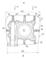
図2に示すように、シリンダ18およびシリンダヘッド20に、複数の冷却フィン34が形成されている。冷却フィン34は、シリンダ18およびシリンダヘッド20の表面積を増やして冷却効果を向上させるために設けられている。冷却フィン34は、板状に形成されて、シリンダ軸心C1と直交する方向に延びる。また、冷却フィン34は、その厚み方向がシリンダ軸心C1と平行に延びるように配置されている。冷却フィン34は、間隔を開けてシリンダ軸心C1の方向に並んで配置されている。詳細には、冷却フィン34は、気筒に対して車幅方向両側および前方に形成されている。シリンダ軸心C1方向に隣接する冷却フィン34は、シリンダ軸心C1方向に延びる縦壁36により連結されている。
As shown in FIG. 2 , a plurality of cooling
図3に示すように、冷却フィン34は、車幅方向寸法が前方に向かって徐々に大きくなっている。つまり、冷却フィン34は、前縁の車幅方向寸法W1が後縁の車幅方向寸法W2よりも大きな台形形状である。冷却フィン34の前側は、フロントフェンダ28で案内された走行風が最初に多く当たる部位であるので、幅広い面積で走行風を受けることで、放熱効果を高めて冷却性能を向上させることができる。
As shown in FIG. 3, the cooling
図1に示すように、シリンダヘッド20の右側部(車幅方向一側部)に、点火プラグ38が突出して取り付けられている。点火プラグ38は、燃焼室35の中で火花点火を行う。図5に示すように、シリンダヘッド20には、点火プラグ38を取り付けるためのプラグ取付部40が形成されている。プラグ取付部40は、残余の部分に対してボス形状に形成されて、シリンダヘッド20の上面から上方に突出している。ボス形状のプラグ取付部40に、雌ねじ部40aが形成されている。
As shown in FIG. 1, a
点火プラグ38は、外周部に雄ねじ部38aが形成され、雄ねじ部38aの先端にスパーク発生部38bが設けられている。点火プラグ38は、雄ねじ部38aがプラグ取付部40の雌ねじ部40aにねじ込まれて、スパーク発生部38bが燃焼室35に臨んでいる。
The
図2に示すように、シリンダヘッド20の前部に、前方に開口する導風孔42が形成されている。図2では、導風孔42をクロスハッチングで示している。本実施形態では、車幅方向に間隔を開けて並ぶ縦壁36,36の間に、導風孔42が形成されている。図4に示すように、導風孔42は、プラグ取付部40の周囲の空間となるプラグ近傍空間SP1とシリンダヘッド20の前方の空間となる前方空間SP2とを連通して、走行風Aを導風孔42からプラグ近傍空間SP1に導く。
As shown in FIG. 2, the front portion of the
本実施形態では、図2に示すように、導風孔42の一部が、シリンダヘッド20の前方に配置されたダウンフレーム部材1b(車体フレームFR)に対して、車幅方向の一側方(右側方)にずれた領域に形成されている。
In the present embodiment, as shown in FIG. 2, a portion of the
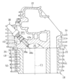
図4に示すように、シリンダヘッド20に、プラグ近傍空間SP1に連通する側方出口44と後方出口46とが形成されている。側方出口44は、プラグ近傍空間SP1から車幅方向一側方(右側方)に開口する。後方出口46は、プラグ近傍空間SP1から車幅方向他方側(左側)にずれて配置され、後方に開口する。
As shown in FIG. 4, the
シリンダヘッド20は、プラグ近傍空間SP1と後方出口46との間に、冷却用の縦フィン45が形成されている。縦フィン45は、板状に形成されてシリンダ軸心C1方向に延びる。また、縦フィン45は、燃焼室35の上部に形成されている。縦フィン45は、プラグ近傍空間SP1から後方出口46に連なって、プラグ近傍空間SP1と後方出口46との車幅方向間の空間に配置される。縦フィン45は、前端部から後方に進むにつれて後方出口46に向かうように車幅方向に傾斜して配置されている。これによって、縦フィン45に衝突した走行風による冷却効果の向上を図るとともに、走行風を後方出口46に導き易くすることができる。
また、縦フィン45は、前後方向に複数並んで配置されるとともに、走行風の流れ方向に複数並んで配置されている。本実施形態では、縦フィン45は、前後方向および左右方向に複数並んで配置されている。走行風の流れ方向に並ぶ縦フィン45は、流れ方向に間隔をあけて配置されている。また、流れ方向下流の縦フィン45は、前後方向にずれて配置されている。言い換えると、流れ方向下流の縦フィン45は、流れ方向上流に並ぶ2つの縦フィン45のピッチ間に配置されている。これによって、流れ方向上流側の縦フィン45に案内された走行風が、流れ方向下流側の縦フィン45に衝突しやすくなり、走行風と縦フィン45との熱交換を促進させることができる。
A plurality of
図2に示すように、縦壁36に、前方に開口した補助導風孔48が形成されている。補助導風孔48は、導風孔42とは異なる位置に形成されて、上下方向に並ぶ冷却フィン34の間に形成されている。つまり、補助導風孔48も、上下方向に並んで設けられている。補助導風孔48は、縦壁36を前後方向に貫通している。図5に示すように、上下に隣接する補助導風孔48は、縦壁36に形成された縦孔50により連通している。縦孔50は、シリンダ軸心C1に沿ってほぼ上下方向に延びており、縦壁36を上下方向に貫通している。
As shown in FIG. 2, the
図2に示すように、排気管25は、導風孔42の車幅方向外側に隣接した位置に配置されている。排気管25は、シリンダヘッド20の前面の排気ポート20bから前方に向かうにつれて、導風孔42に対して、車幅方向に離れる方向、具体的には、車幅方向他側方(左側方)に延びた後、湾曲して下方に延び、さらに、シリンダ20よりも下方で車幅方向一側方(右側方)に向かって延びている。排気管25は、さらに、上方に湾曲した後、シリンダ18の車幅方向一側方(右側方)で後方に向かって湾曲し、シリンダ18の右側方を後方に向かって延びている。
As shown in FIG. 2 , the
換言すれば、排気管25は、シリンダヘッド20の前面から前方に向かって車幅方向他側方(左側方)に延びる第1部分51と、第1部分51の下流端からシリンダ18の下方まで下方に延びる第2部分52と、第2部分52の下端からシリンダ18の車幅方向一側方(右側方)まで車幅方向に延びる第3部分53と、第3部分53の下流端からシリンダ18の車幅方向一側方(右側方)を後方に延びる第4部分54とを有している。本実施形態では、排気管25の第3部分53は、右側方に向かって下方に湾曲しながら延びた後、車幅方向中間部から上方に湾曲しながら右側方に向かって延びている。
In other words, the
このように、本実施形態の排気管25は、正面視において、第2部分52がシリンダヘッド20およびシリンダ18と重なることなく、車幅方向および上下方向に湾曲しながら延びている。これにより、排気管25の第2部分52が、冷却フィン34に向かう走行風を阻害するのを抑制することができる。また、排気管25は、十分な排気管長を確保して、排気効率を高く維持することができる。
As described above, the
図1に示すフロントフェンダ28の後部28rに、導風孔42に向けて走行風Aを案内するガイド部56が形成されている。詳細には、フロントフェンダ28は、フェンダ前部28fと、フェンダ中間部28iと、フェンダ後部28rとを有している。フェンダ中間部28iは、フェンダ後部28rよりも前方に位置して、フェンダ前部28fとフェンダ後部28rとを繋ぐ。本実施形態では、フェンダ中間部28iは、左右のフロントフォーク6の間の部分とその近傍部分を含む。フェンダ中間部28iよりも前方がフェンダ前部28fを構成し、フェンダ中間部28iよりも後方がフェンダ後部28rを構成する。
A
フロントフェンダ28の前端28faは、前輪8の車軸AXよりも前方に位置している。より詳細には、フロントフェンダ28の前端28faは、前輪8のブレーキキャリパ55によって挟圧されるブレーキディスク57の前縁よりも前方に位置している。
A
図6はフロントフェンダ28の底面図である。図6に示すように、フェンダ前部28fは、フェンダ中間部28iおよびフェンダ後部28rよりも車幅方向寸法が幅広に形成されている。
6 is a bottom view of the
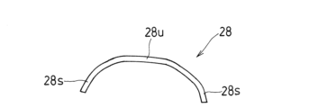
フェンダ中間部28iは、その前端から後方に向かって徐々に車幅方向寸法が小さくなっている。また、フロントフェンダ28は全体に渡って、図7に示すように、上壁28uと左右の側壁28sとで下方に開口した横断面カップ形となっており、走行風Aが側方に逃げないように後方へ案内される。これにより、図6に示すように、フロントフェンダ28の内側(下側)に入った走行風Aが、フェンダ中間部28iで絞られることで流速が上がるので、走行風Aを効果的に案内できる。
The fender
フェンダ中間部28iの前端の車幅方向寸法W3と、最も幅が狭くなる部分の車幅方向寸法W4との寸法比(W3/W4)は、例えば、1.3~2.0倍である。この寸法比(W3/W4)が1.3倍未満、すなわち、前端部分寸法W3と幅狭部分寸法W4との差が小さ過ぎると、走行風の流速を上げる効果が十分に得られない。また、寸法比(W3/W4)が2.0倍超過、すなわち、前端部分寸法W3と幅狭部分寸法W4の差が大き過ぎると、フェンダ前部28fが幅広となって重量が増加してしまう。ここで、前端部分寸法W3および幅狭部分寸法W4は、フロントフェンダ28の内面の幅寸法である。
A dimensional ratio (W3/W4) between the vehicle width direction dimension W3 of the front end of the fender
フェンダ後部28rは、図1に示すように、前後方向長さが短く、後方に向かって下方に傾斜している。フェンダ後部28rは、導風孔42に向かうように走行風Aが案内されるように傾斜している。本実施形態では、フェンダ後部28rの下端28raは、導風孔42よりも上方に位置している。また、本実施形態では、上述のように、フロントフェンダ28の下端28raが、シリンダヘッドカバー22の上端よりも上方に位置している。フロントフェンダ28の下端28ra(後端)は、走行時にフロントフェンダ28が左右に回動または上下に振動した場合でもダウンフレーム部材1bとのクリアランスを確保できるように配置されている。
As shown in FIG. 1, the fender
フェンダ後部28rの傾斜角度は、ガイド部56で案内された走行風Aが導風孔42に向かうように設定されている。これにより、シリンダヘッド20において比較的高温となるプラグ取付部40に走行風を導くことができ、シリンダヘッド20全体としての冷却効率を高めることができる。
The inclination angle of the fender
ガイド部56は、フェンダ後部28rの下面(内面)に形成されている。図6に示すように、ガイド部56は、前方から流れる走行風を受けて下方に偏向させる偏向面58と、偏向面58の左右両側に形成されて偏向面58から下方に延びる側壁面60,60とを有している。側壁面60,60により、偏向面58に沿って後方に流れる走行風Aが、車幅方向外側に逸れるのを防ぐことができる。したがって、偏向面58で案内した走行風Aを効果的に冷却フィン34および導風孔42に導くことができる。これにより、エンジンEの冷却効果が向上する。
The
図1に示すように、偏向面58に沿って下方に延長した仮想延長面VSは、シリンダヘッド20の前方の領域を通過する。仮想延長面VSに沿って流れる走行風Aと、シリンダヘッド20の前方の領域の走行風Aが衝突することで、シリンダヘッド20の前面に向かう走行風量を増やすことができる。これにより、エンジンEの冷却効果をさらに高めることができる。
As shown in FIG. 1 , an imaginary extension plane VS extending downward along the
本実施形態の導風構造の作用を説明する。自動二輪車が走行すると、前輪8とフロントフェンダ28の間を通過する走行風Aが、フロントフェンダ28のガイド部56によってエンジンEの前面に向かって導かれる。走行風Aは、ダウンフレーム部材1bで左右方向に分岐され、冷却フィン34に沿って後方に流れる。これにより、シリンダ18およびシリンダヘッド20が冷却される。
The operation of the air guide structure of this embodiment will be described. When the motorcycle runs, running wind A passing between the
また、走行風Aの一部が、導風孔42からシリンダヘッド20の内部に導かれる。図4に示すように、導風孔42からシリンダヘッド20の内部に導かれた走行風Aは、プラグ近傍空間SP1を通過する。プラグ取付部40が、プラグ近傍空間SP1内で上方に突出しているので、プラグ取付部40に走行風Aが衝突し易い。これにより、高温になり易いプラグ取付部40の近傍を効果的に冷却できる。
Also, part of the running wind A is guided into the
また、走行風Aの一部が、図2に示す補助導風孔48に導かれる。図5に示すように、補助導風孔48は、縦壁36を前後方向に貫通すると共に、隣接する補助導風孔48が縦孔50により連通している。したがって、補助導風孔48に導かれた走行風Aは、前後方向および上下方向に向かって、冷却フィン34と冷却フィン34との間を流れる。これにより、エンジンEの冷却効果が向上する。
Also, part of the running wind A is guided to the auxiliary
上記構成によれば、図1に示すフロントフェンダ28のフェンダ後部28rによって走行風Aを導風孔42に向けて案内している。これにより、高温になり易いプラグ取付部40の近傍を効果的に冷却することができる。したがって、導風孔42を通って走行風Aが円滑に点火プラグ38のプラグ取付部40の周囲に導かれるので、シリンダヘッド20の冷却効果を高めることができる。冷却効果が上がると、エンジン出力を上げることができる。しかも、シリンダヘッド20に導風孔42を形成し、フェンダ後部28rにガイド部56を設けるだけなので、部品点数も増加しない。
According to the above configuration, the running wind A is guided toward the
図4に示すように、導風孔42からシリンダヘッド20の内部に案内された走行風Aは、プラグ取付部40を冷却した後、車幅方向側方に開口する側方出口44と、後方に開口する後方出口46とから外部に排出される。これにより、プラグ取付部40の周囲の空間SP1に案内された走行風Aが排出され易く、走行風Aがスムースに流れる。その結果、シリンダヘッド20の冷却効果を高めることができる。
As shown in FIG. 4 , the running wind A guided into the
図1に示すフロントフェンダ28のフェンダ後部28rの下端28raが、シリンダヘッドカバー22の下端よりも上方に位置している。図2の正面視で、フェンダ後部28rとシリンダヘッド20が重ならないので、フロントフェンダ28がシリンダヘッド20に向かう走行風を阻害するのを防ぐことができる。また、図1に示すガイド部56によって案内される走行風Aにより、フェンダ後部28rの下端28raとシリンダヘッドカバー22の下端の間を前後方向に流れる走行風Aもシリンダヘッド20の前面に向かわせることができる。その結果、シリンダヘッド20への走行風量が増えて、シリンダヘッド20の冷却効果を高めることができる。
A lower end 28ra of a fender
図6に示すように、フェンダ前部28fがフェンダ後部28rよりも車幅方向寸法が幅広に形成され、フェンダ中間部28iが、前端から後方に向かって徐々に車幅方向寸法が小さくなっている。幅広のフェンダ前部28fによって多くの走行風Aを集めることができる。しかも、フェンダ前部28fの前端28faはブレーキディスク57よりも前方まで延びているので、より多くの走行風Aを集めることができる。
As shown in FIG. 6, the
また、後方に向かって徐々に車幅方向寸法が小さくなるフェンダ中間部28iによって、フェンダ前部28fで集められた走行風Aの流速を高めることができる。さらに、導風孔42に向かって傾斜したフェンダ後部28rによって、流速が大きくなった走行風Aがシリンダヘッド20の前面に案内される。これにより、シリンダヘッド20の冷却効果を高めることができる。
In addition, the fender
図1に示すように、フェンダ後部28rの下端28raがシュラウド部32の下端32aよりも上方に位置し、かつ、シュラウド部32の前縁部32bよりも後方に位置している。このシュラウド部32によって、フロントフェンダ28で案内された走行風Aが車幅方向外側に逸れるのを防ぐことができる。したがって、図2に示すように、走行風Aがシリンダヘッド20に向かい易くなり、シリンダヘッド20の冷却効果を高めることができる。
As shown in FIG. 1 , the lower end 28ra of the fender
シリンダヘッド20の前面に接続された排気管25が、シリンダヘッド20の前面から前方に向かって導風孔42と車幅方向反対側(左側)に延びている。したがって、導風孔42に向かう走行風Aの流れを排気管25が阻害するのを防ぐことができる。これにより、シリンダヘッド20の冷却効果を高めることができる。
An
排気管25は、さらに、シリンダ18の下端よりも下方に延びて、シリンダ18の下方を右側に延びた後、上方に屈曲してシリンダ18の右側方を後方に延びている。これにより、十分な排気管長を確保して排気効果を高く維持しながら、排気管25が走行風Aを阻害するのを防いでシリンダ18およびシリンダヘッド20の冷却効果を高めることができる。
The
図2に示す導風孔42の一部が、シリンダヘッド20の前方に配置されたダウンフレーム部材1bに対して、車幅方向にずれた領域に形成されている。したがって、ダウンフレーム部材1bに当たって車幅方向に逸れた走行風Aが、導風孔42に向かって流れ易い。これにより、シリンダヘッド20の冷却効果を高めることができる。
A portion of the
本発明は、以上の実施形態に限定されるものでなく、本発明の要旨を逸脱しない範囲内で、種々の追加、変更または削除が可能である。例えば、上記実施形態では、エンジンEの前方にダウンフレーム部材1bが設けられていたが、ダウンフレーム部材1bはなくてもよい。また、上記実施形態では、エンジンEの前方にサイドカバー30が設けられていたが、サイドカバー30はなくてもよい。したがって、そのようなものも本発明の範囲内に含まれる。
The present invention is not limited to the above embodiments, and various additions, changes, or deletions are possible without departing from the scope of the present invention. For example, in the above embodiment, the
1 メインフレーム(車体フレーム)
1b ダウンフレーム部材(車体フレーム)
18 シリンダ
20 シリンダヘッド
22 シリンダヘッドカバー
28 フロントフェンダ
28f フェンダ前部
28i フェンダ中間部
28r フェンダ後部
30 シュラウド
38 点火プラグ
42 導風孔
44 側方出口
46 後方出口
51 第1部分
56 ガイド部
A 走行風
E 空冷エンジン
SP1 プラグ近傍空間(取付部分周囲の空間)
SP2 前方空間
1 Main frame (body frame)
1b Down frame member (body frame)
18
SP2 forward space
Claims (8)
前記空冷エンジンのシリンダおよびシリンダヘッドに、シリンダ軸心と直交する方向に延びる複数の冷却フィンが形成され、
前記シリンダ軸心方向に隣接する前記冷却フィンは、前記シリンダ軸心方向に延びる縦壁により連結され、
前記シリンダヘッドの前部に、前方に開口して、点火プラグの取付部分周囲の空間と前記シリンダヘッドの前方の空間とを連通する導風孔が形成され、
前記導風孔は、車幅方向に間隔を開けて並ぶ前記縦壁の間に形成され、
前記フロントフェンダに、前記導風孔に向けて走行風を案内するガイド部が形成され、
さらに、前方に開口した複数の補助導風孔が前記縦壁を前後方向に貫通して形成され、
前記補助導風孔は、前記シリンダ軸心方向に並ぶ前記冷却フィンの間に形成され、
前記シリンダ軸心に沿って前記縦壁を貫通して延びる縦孔が、前記補助導風孔に連通しているエンジン冷却構造。
An engine cooling structure for a motorcycle comprising an air-cooled engine as a drive source and a front fender disposed in front of the air-cooled engine,
A plurality of cooling fins extending in a direction orthogonal to the cylinder axis are formed on the cylinder and cylinder head of the air-cooled engine,
the cooling fins adjacent to each other in the axial direction of the cylinder are connected by a vertical wall extending in the axial direction of the cylinder;
An air guide hole is formed in a front portion of the cylinder head, opening forward and communicating a space around a mounting portion of the spark plug and a space in front of the cylinder head,
The air guide holes are formed between the vertical walls spaced apart in the vehicle width direction,
A guide portion is formed in the front fender for guiding running air toward the air guide hole,
Furthermore, a plurality of auxiliary air guide holes that open forward are formed through the vertical wall in the front-rear direction,
The auxiliary air guide hole is formed between the cooling fins arranged in the axial direction of the cylinder,
The engine cooling structure , wherein a vertical hole extending through the vertical wall along the cylinder axis communicates with the auxiliary air guide hole .
前記フェンダ前部は、前記フェンダ後部よりも車幅方向寸法が幅広に形成され、
前記フェンダ中間部は、その前端から後方に向かって徐々に車幅方向寸法が小さくなっているエンジン冷却構造。 3. The engine cooling structure according to claim 1, wherein the front fender includes a fender front portion, a fender rear portion, and a fender intermediate portion located forward of the fender rear portion and connecting the fender front portion and the fender rear portion. and
The fender front portion is wider than the fender rear portion in the vehicle width direction,
The engine cooling structure, wherein the fender intermediate portion has a vehicle width direction dimension that gradually decreases rearward from the front end thereof.
前記フロントフェンダの後部の下端が、前記シュラウドの前縁部よりも後方に位置しているエンジン冷却構造。 4. The engine cooling structure according to any one of claims 1 to 3, wherein a shroud is provided forward of the cylinder head and covers a portion of the vehicle body frame from the outside in the vehicle width direction,
The engine cooling structure, wherein the lower end of the rear portion of the front fender is positioned rearward of the front edge portion of the shroud.
前記排気管は、前記シリンダヘッドの前面から前方に向かうにつれて、前記導風孔に対して車幅方向に離れる方向に延びる第1部分を有しているエンジン冷却構造。 5. The engine cooling structure according to any one of claims 1 to 4, wherein an exhaust pipe is connected to the front surface of the cylinder head,
The engine cooling structure, wherein the exhaust pipe has a first portion extending in a direction away from the air guide hole in the vehicle width direction as it goes forward from the front surface of the cylinder head.
Priority Applications (2)
| Application Number | Priority Date | Filing Date | Title |
|---|---|---|---|
| JP2018242098A JP7274860B2 (en) | 2018-12-26 | 2018-12-26 | Motorcycle engine cooling structure |
| US16/684,393 US11565583B2 (en) | 2018-12-26 | 2019-11-14 | Engine cooling structure for motorcycle |
Applications Claiming Priority (1)
| Application Number | Priority Date | Filing Date | Title |
|---|---|---|---|
| JP2018242098A JP7274860B2 (en) | 2018-12-26 | 2018-12-26 | Motorcycle engine cooling structure |
Publications (3)
| Publication Number | Publication Date |
|---|---|
| JP2020105920A JP2020105920A (en) | 2020-07-09 |
| JP2020105920A5 JP2020105920A5 (en) | 2021-12-16 |
| JP7274860B2 true JP7274860B2 (en) | 2023-05-17 |
Family
ID=71122481
Family Applications (1)
| Application Number | Title | Priority Date | Filing Date |
|---|---|---|---|
| JP2018242098A Active JP7274860B2 (en) | 2018-12-26 | 2018-12-26 | Motorcycle engine cooling structure |
Country Status (2)
| Country | Link |
|---|---|
| US (1) | US11565583B2 (en) |
| JP (1) | JP7274860B2 (en) |
Families Citing this family (2)
| Publication number | Priority date | Publication date | Assignee | Title |
|---|---|---|---|---|
| CN112918598A (en) * | 2021-03-25 | 2021-06-08 | 深圳东博士科技有限公司 | Electric scooter with dual waterproof intelligent control box |
| US20220379718A1 (en) * | 2021-05-28 | 2022-12-01 | Richard Mellick Zock | Air channeling assembly for all-terrain vehicles |
Citations (5)
| Publication number | Priority date | Publication date | Assignee | Title |
|---|---|---|---|---|
| JP2005098249A (en) | 2003-09-26 | 2005-04-14 | Honda Motor Co Ltd | Cooling air passage structure for cylinder head |
| JP2006015930A (en) | 2004-07-02 | 2006-01-19 | Honda Motor Co Ltd | Fender structure for motorcycle |
| JP2009161021A (en) | 2007-12-28 | 2009-07-23 | Yamaha Motor Co Ltd | Saddle type vehicle |
| JP2013072384A (en) | 2011-09-28 | 2013-04-22 | Honda Motor Co Ltd | Variable valve device of internal combustion engine |
| JP2016097864A (en) | 2014-11-25 | 2016-05-30 | 本田技研工業株式会社 | Front fender for saddle-riding type vehicle |
Family Cites Families (9)
| Publication number | Priority date | Publication date | Assignee | Title |
|---|---|---|---|---|
| JPS5945268U (en) * | 1982-09-20 | 1984-03-26 | 本田技研工業株式会社 | Ventilation equipment for motorcycles, etc. |
| US7124731B2 (en) * | 2003-09-19 | 2006-10-24 | Honda Motor Co., Ltd. | Internal combustion engine with oil temperature sensor |
| JP2009161015A (en) * | 2007-12-28 | 2009-07-23 | Yamaha Motor Co Ltd | Front fender for motor cycle and motor cycle |
| JP5829907B2 (en) * | 2011-12-28 | 2015-12-09 | 川崎重工業株式会社 | Saddle riding vehicle |
| JP5930376B2 (en) * | 2012-02-16 | 2016-06-08 | 本田技研工業株式会社 | Saddle riding vehicle |
| JP5897985B2 (en) * | 2012-05-17 | 2016-04-06 | 本田技研工業株式会社 | Front wind guide structure in motorcycles |
| JP6280483B2 (en) * | 2014-09-30 | 2018-02-14 | 本田技研工業株式会社 | Cooling structure for saddle-ride type vehicles |
| JP6139587B2 (en) * | 2015-03-11 | 2017-05-31 | 本田技研工業株式会社 | Front structure of motorcycle |
| JP6654181B2 (en) * | 2017-12-28 | 2020-02-26 | 本田技研工業株式会社 | Canister arrangement structure for saddle type vehicle |
-
2018
- 2018-12-26 JP JP2018242098A patent/JP7274860B2/en active Active
-
2019
- 2019-11-14 US US16/684,393 patent/US11565583B2/en active Active
Patent Citations (5)
| Publication number | Priority date | Publication date | Assignee | Title |
|---|---|---|---|---|
| JP2005098249A (en) | 2003-09-26 | 2005-04-14 | Honda Motor Co Ltd | Cooling air passage structure for cylinder head |
| JP2006015930A (en) | 2004-07-02 | 2006-01-19 | Honda Motor Co Ltd | Fender structure for motorcycle |
| JP2009161021A (en) | 2007-12-28 | 2009-07-23 | Yamaha Motor Co Ltd | Saddle type vehicle |
| JP2013072384A (en) | 2011-09-28 | 2013-04-22 | Honda Motor Co Ltd | Variable valve device of internal combustion engine |
| JP2016097864A (en) | 2014-11-25 | 2016-05-30 | 本田技研工業株式会社 | Front fender for saddle-riding type vehicle |
Also Published As
| Publication number | Publication date |
|---|---|
| US20200207202A1 (en) | 2020-07-02 |
| JP2020105920A (en) | 2020-07-09 |
| US11565583B2 (en) | 2023-01-31 |
Similar Documents
| Publication | Publication Date | Title |
|---|---|---|
| US7448461B2 (en) | Cowl structure of vehicle | |
| JP5771100B2 (en) | Saddle riding vehicle | |
| US9850863B2 (en) | Air intake duct of saddle-ridden vehicle | |
| WO2010137621A1 (en) | Two-wheeled motor vehicle | |
| JP6649083B2 (en) | Motorcycle | |
| JP4856485B2 (en) | Motorcycle cowling structure | |
| JP7274860B2 (en) | Motorcycle engine cooling structure | |
| JP6254511B2 (en) | Front fender for saddle-ride type vehicles | |
| JP2019038290A (en) | Saddle-riding type vehicle and radiator air guiding device | |
| JP5837777B2 (en) | Saddle riding vehicle | |
| US10960753B2 (en) | Saddle riding vehicle | |
| JP2013136342A (en) | Straddle-type vehicle | |
| JP4802727B2 (en) | Rough terrain vehicle | |
| JP2012245795A (en) | Two-wheeled motor vehicle | |
| JP6991451B2 (en) | Motorcycle | |
| US11180021B2 (en) | Vehicle | |
| JP6593085B2 (en) | Wind guide structure of front fender of motorcycle | |
| JP5932382B2 (en) | Saddle riding vehicle | |
| JP5807446B2 (en) | Engine cooling structure | |
| JP4579127B2 (en) | Engine cooling structure for saddle riding type vehicles | |
| JP7453012B2 (en) | air-cooled internal combustion engine | |
| JP2020502426A (en) | Motorcycle engine cooling system | |
| JPH09249170A (en) | Vehicle of motor scooter type | |
| JP6147534B2 (en) | Saddle riding vehicle | |
| CN108374713B (en) | Cooling system for internal combustion engine |
Legal Events
| Date | Code | Title | Description |
|---|---|---|---|
| A521 | Request for written amendment filed |
Free format text: JAPANESE INTERMEDIATE CODE: A523 Effective date: 20211104 |
|
| A621 | Written request for application examination |
Free format text: JAPANESE INTERMEDIATE CODE: A621 Effective date: 20211104 |
|
| A711 | Notification of change in applicant |
Free format text: JAPANESE INTERMEDIATE CODE: A712 Effective date: 20220124 |
|
| A131 | Notification of reasons for refusal |
Free format text: JAPANESE INTERMEDIATE CODE: A131 Effective date: 20220823 |
|
| A977 | Report on retrieval |
Free format text: JAPANESE INTERMEDIATE CODE: A971007 Effective date: 20220824 |
|
| A521 | Request for written amendment filed |
Free format text: JAPANESE INTERMEDIATE CODE: A523 Effective date: 20221018 |
|
| A131 | Notification of reasons for refusal |
Free format text: JAPANESE INTERMEDIATE CODE: A131 Effective date: 20221213 |
|
| A521 | Request for written amendment filed |
Free format text: JAPANESE INTERMEDIATE CODE: A523 Effective date: 20230213 |
|
| TRDD | Decision of grant or rejection written | ||
| A01 | Written decision to grant a patent or to grant a registration (utility model) |
Free format text: JAPANESE INTERMEDIATE CODE: A01 Effective date: 20230404 |
|
| A61 | First payment of annual fees (during grant procedure) |
Free format text: JAPANESE INTERMEDIATE CODE: A61 Effective date: 20230502 |
|
| R150 | Certificate of patent or registration of utility model |
Ref document number: 7274860 Country of ref document: JP Free format text: JAPANESE INTERMEDIATE CODE: R150 |