Die vorliegende Erfindung betrifft eine Kühlsteuer/regeleinheit für einen wassergekühlten Mehrzylinderverbrennungsmotor mit einem Zylinderdeaktivierungsmechanismus.The present invention relates to a cooling control unit for a water-cooled multi-cylinder internal combustion engine having a cylinder deactivation mechanism.
Aus der DE 35 22 988 C2 ist eine Kühlsteuer/regeleinheit für einen wassergekühlten Mehrzylinderverbrennungsmotor mit einem Zylinderdeaktivierungsmechanismus bekannt, welcher einen deaktivierungsprogrammierten Zylinder und einen normal aktivierten Zylinder umfasst, um die Zylinder gemäß dem Motorbetriebszustand teilweise zu deaktivieren. Die Kühlsteuer/regeleinheit umfasst einen Verbindungsdurchgang, durch welchen ein Normal-Aktivierter-Zylinder-Kühlmittelmantel und ein Deaktivierungsprogrammierter-Zylinder-Kühlmittelmantel miteinander in Verbindung stehen und durch welchen ein Kühlmittel zwischen den Mänteln strömen gelassen wird. Der Normal-Aktivierter-Zylinder-Kühlmittelmantel ist ein Kühlmitteldurchgang, welcher für die normal aktivierten Zylinder ausgebildet ist, und der Deaktivierungsprogrammierter-Zylinder-Kühlmittelmantel ist ein Kühlmitteldurchgang, welcher für die deaktivierungsprogrammierten Zylinder ausgebildet ist. Die Kühlsteuer/regeleinheit umfasst ferner einen Bypassdurchgang, welcher von dem Verbindungsdurchgang abzweigt und welcher den Deaktivierungsprogrammierter-Zylinder-Kühlmittelmantel umgeht, ein Ableitungssteuer/regelventil, welches an einem Ableitungsabschnitt vorgesehen ist, wo der Bypassdurchgang von dem Verbindungsdurchgang abzweigt, und ein Steuer/Regelmittel, um das Ableitungssteuer/regelventil gemäß dem Betriebszustand des Verbrennungsmotors zu steuern/regeln.From the DE 35 22 988 C2 For example, a cooling control unit for a water-cooled multi-cylinder internal combustion engine having a cylinder deactivation mechanism is known which includes a deactivated-programmed cylinder and a normally-activated cylinder to partially deactivate the cylinders according to the engine operating condition. The cooling control unit includes a communication passage through which a normally-activated cylinder coolant jacket and a deactivation-programmed cylinder coolant jacket communicate with each other and through which a coolant is flowed between the shrouds. The normal-activated-cylinder coolant jacket is a coolant passage formed for the normally-activated cylinders, and the deactivation-programmed-cylinder coolant jacket is a coolant passage formed for the deactivated-programmed cylinders. The cooling control unit further includes a bypass passage that branches off from the communication passage and bypasses the deactivation programmed cylinder coolant jacket, a bleed control valve provided at a bleeding section where the bypass passage branches off from the communication passage, and a control means; to control the derivative control valve according to the operating state of the internal combustion engine.
Die WO 2003/048548 A1 offenbart eine Kühlsteuer/regeleinheit für einen wassergekühlten Mehrzylinderverbrennungsmotor mit einem Zylinderdeaktivierungsmechanismus, wobei die Kühlsteuer/regeleinheit dazu ausgebildet ist, eine Kühlmittelströmung zu einer deaktivierten Zylinderbank zu unterbrechen.The WO 2003/048548 A1 discloses a cooling control unit for a water-cooled multi-cylinder internal combustion engine having a cylinder deactivation mechanism, wherein the cooling control unit is configured to interrupt a flow of coolant to a deactivated cylinder bank.
Im Falle eines Mehrzylinderverbrennungsmotors von einem Typ, welcher in der Lage ist, einige seiner Zylinder zu deaktivieren bzw. abzuschalten, sind Zylinder, welche für einen langen Zeitraum deaktiviert wurden, manchmal unvollständig aufgewärmt, wenn der Motor zu einem Betriebszustand zurückkehrt, in welchem alle Zylinder aktiviert sind.In the case of a multi-cylinder internal combustion engine of a type capable of deactivating some of its cylinders, cylinders which have been deactivated for a long period of time are sometimes incompletely warmed up when the engine returns to an operating condition in which all cylinders are activated.
Um einen unvollständigen Aufwärmzustand zu verhindern, wird ein bestimmter Mehrzylinderverbrennungsmotor derart gesteuert/geregelt, dass die Motorventile wiederholt ihre eigene Aktivierung und Deaktivierung gemäß voran gehend gesetzten Motorventilbetriebs- und -stoppmodi wechseln können, während der Motor arbeitet, wobei einige der Zylinder deaktiviert sind (siehe beispielsweise japanische Patentanmeldung Nr. Hei 8-93516 , nachfolgend Patentdokument 1 bezeichnet).In order to prevent an incomplete warm-up condition, a particular multi-cylinder internal combustion engine is controlled such that the engine valves can repeatedly change their own activation and deactivation in accordance with previously set engine valve operating and stopping modes while the engine is operating, with some of the cylinders deactivated (see for example Japanese Patent Application No. Hei 8-93516 hereinafter referred to as Patent Document 1).
Im Falle des Mehrzylinderverbrennungsmotors mit einem Zylinderdeaktivierungsmechanismus, welcher in dem Patentdokument 1 offenbart ist, ist jeder von seinen Zylindern mit Ventilaktivierungs/deaktivierungsschaltmitteln versehen, um seine entsprechenden Motorventile zwischen ihrer Aktivierung und Deaktivierung unabhängig von dem Rest der Zylinder zu schalten.In the case of the multi-cylinder internal combustion engine having a cylinder deactivation mechanism disclosed in Patent Document 1, each of its cylinders is provided with valve activation / deactivation switching means for switching its respective engine valves independently of the rest of the cylinders between their activation and deactivation.
In diesem Fall sind die mehrfachen Zylinder mit ihren jeweiligen Ventilaktivierungs/deaktivierungsschaltmitteln versehen. Dies erhöht die Teilezahl und macht die Steuerung/Regelung der Zylinder kompliziert. Zusätzlich macht die Anordnung der Ventilaktivierungs/deaktivierungsschaltmittel die Struktur des Verbrennungsmotors kompliziert und erhöht die Herstellungskosten.In this case, the multiple cylinders are provided with their respective valve activation / deactivation switching means. This increases the number of parts and makes the control of the cylinder complicated. In addition, the arrangement of the valve activation / deactivation switching means complicates the structure of the internal combustion engine and increases the manufacturing cost.
Die vorliegende Erfindung erfolgte im Hinblick auf diese Probleme. Das Ziel der vorliegenden Erfindung ist es, eine einfach aufgebaute Kühlsteuer/regeleinheit für einen wassergekühlten Mehrzylinderverbrennungsmotor mit einem Zylinderdeaktivierungsmechanismus bereitzustellen, wobei die Kühlsteuer/regeleinheit in der Lage ist, eine Kühlmittelströmung zu steuern/regeln und somit in der Lage ist, zu verhindern, dass der Verbrennungsmotor unvollständig aufgewärmt ist, wenn der Verbrennungsmotor zu seinem Betriebszustand zurückkehrt, bei dem alle Zylinder aktiviert sind.The present invention has been made in view of these problems. The object of the present invention is to provide a simply structured cooling control unit for a water-cooled multi-cylinder internal combustion engine having a cylinder deactivation mechanism, wherein the cooling control unit is capable of controlling a coolant flow and thus capable of preventing the internal combustion engine is incompletely warmed up when the internal combustion engine returns to its operating state in which all the cylinders are activated.
Um das vorangehende Ziel zu erreichen, ist eine Erfindung nach Anspruch 1 eine Kühlsteuer/regeleinheit für einen wassergekühlten Mehrzylinderverbrennungsmotor mit einem Zylinderdeaktivierungsmechanismus, umfassend einen deaktivierungsprogrammierten Zylinder und einen normal aktivierten Zylinder, um die Zylinder gemäß dem Motorbetriebszustand teilweise zu deaktivieren. Die Kühlsteuer/regeleinheit umfasst: einen Verbindungsdurchgang, durch welchen ein Normal-Aktivierter-Zylinder-Kühlmittelmantel und ein Deaktivierungsprogrammierter-Zylinder-Kühlmittelmantel miteinander in Verbindung stehen, und durch welchen ein Kühlmittel zwischen den Mänteln strömen gelassen wird, wobei der Normal-Aktivierter-Zylinder-Kühlmittelmantel ein Kühlmitteldurchgang ist, welcher für die normal aktivierten Zylinder ausgebildet ist, und der Deaktivierungsprogrammierter-Zylinder-Kühlmittelmantel ein Kühlmitteldurchgang ist, welcher für die deaktivierungsprogrammierten Zylinder ausgebildet ist; einen Bypassdurchgang, welcher von dem Verbindungsdurchgang abzweigt und welcher den Deaktivierungsprogrammierter-Zylinder-Kühlmittelmantel umgeht; ein erstes Durchflussrateneinstellventil, welches in dem Bypassdurchgang vorgesehen ist; ein zweites Durchflussrateneinstellventil, welches an einer Stelle stromabwärts von einem Ableitungsabschnitt vorgesehen ist, wo der Bypassdurchgang von dem Verbindungsdurchgang abzweigt; und ein Steuer/Regelmittel, um das erste Durchflussrateneinstellventil und das zweite Durchflussrateneinstellventil gemäß dem Betriebszustand des Verbrennungsmotors zu steuern/regeln. Der Verbrennungsmotor wird dabei derart gesteuert/geregelt, dass nur die normal aktivierten Zylinder aktiviert werden sollten, während der Verbrennungsmotor aufgewärmt wird und während ein Fahrzeug normal fährt, und auch derart, dass alle der Zylinder aktiviert werden sollten, während es erforderlich ist, dass der Verbrennungsmotor eine Kraft ausgibt, welche nicht kleiner als eine vorbestimmte Kraft ist. Die Kühlsteuer/regeleinheit zeichnet sich dabei dadurch aus, dass: das Steuer/Regelmittel während der Aufwärmung des Verbrennungsmotors das erste Durchflussrateneinstellventil öffnet und das zweite Durchflussrateneinstellventil schließt, damit das Kühlmittel nach dem Passieren des Normal-Aktivierter-Zylinder-Kühlmittelmantels in den Bypassdurchgang strömen sollte, ohne den Deaktivierungsprogrammierter-Zylinder-Kühlmittelmantel zu passieren; nach der Beendigung der Aufwärmung, bei der die Temperatur des Kühlmittels in dem Normal-Aktivierter-Zylinder-Kühlmittelmantel auf eine vorbestimmte Temperatur ansteigt, das Steuer/Regelmittel das erste Durchflussrateneinstellventil und das zweite Durchflussrateneinstellventil derart steuert/regelt, dass das Kühlmittel nach dem Passieren des Normal-Aktivierter-Zylinder-Kühlmittelmantels in einer adäquaten Menge in den Deaktivierungsprogrammierter-Zylinder-Kühlmittelmantel strömen sollte, und zwar derart, dass die Menge nicht erlauben sollte, dass die Temperatur des Kühlmittels in dem Normal-Aktivierter-Zylinder-Kühlmittelmantel unter eine separat eingestellte vorbestimmte unterste Kühlmitteltemperatur fallen sollte; und während alle Zylinder aktiviert sind, das Steuer/Regelmittel das erste Durchflussrateneinstellventil schließt und das zweite Durchflussrateneinstellventil öffnet, damit das Kühlmittel nach dem Passieren des Normal-Aktivierter-Zylinder-Kühlmittelmantels in den Deaktivierungsprogrammierter-Zylinder-Kühlmittelmantel strömen sollte, ohne den Bypassdurchgang zu passieren.To achieve the foregoing object, an invention according to claim 1 is a cooling control unit for a water-cooled multi-cylinder internal combustion engine having a cylinder deactivation mechanism comprising a deactivation-programmed cylinder and a normally-activated cylinder to partially deactivate the cylinders according to the engine operating condition. The cooling control unit includes: a communication passage through which a normal-activated-cylinder coolant jacket and a deactivation-programmed cylinder coolant jacket communicate with each other, and through which a coolant is flowed between the shrouds, the normal-activated cylinder Coolant jacket is a coolant passage formed for the normally activated cylinders and the deactivation programmed cylinder coolant jacket is a coolant passage formed for the deactivated programmed cylinders; a bypass passage branching from the communication passage and bypassing the deactivation programmed cylinder coolant jacket; a first flow rate adjustment valve provided in the bypass passage; a second flow rate adjustment valve, which is provided at a position downstream of a discharge portion where the bypass passage branches off from the communication passage; and a control means for controlling the first flow rate adjustment valve and the second flow rate adjustment valve according to the operating state of the internal combustion engine. The internal combustion engine is thereby controlled so that only the normally activated cylinders should be activated while the internal combustion engine is being warmed up and while a vehicle is running normally, and also such that all of the cylinders should be activated while it is required that Engine outputs a force which is not less than a predetermined force. The cooling control unit is characterized in that: during the warm-up of the internal combustion engine, the control means opens the first flow rate adjustment valve and closes the second flow rate adjustment valve to allow the coolant to flow into the bypass passage after passing the normally-activated cylinder coolant jacket without passing the deactivation programmed cylinder coolant jacket; after the completion of the warm-up, in which the temperature of the coolant in the normal-activated-cylinder coolant jacket increases to a predetermined temperature, the control means controls the first flow rate adjustment valve and the second flow rate adjustment valve such that the coolant after passing the Normal-activated cylinder coolant jacket should flow in an amount sufficient in the deactivation programmed cylinder coolant jacket, such that the amount should not allow the temperature of the coolant in the normal-activated-cylinder coolant jacket below a separately set predetermined lowest coolant temperature should fall; and while all of the cylinders are activated, the control means closes the first flow rate adjustment valve and opens the second flow rate adjustment valve to allow the coolant to flow into the deactivation programmed cylinder coolant jacket after passing the normally-activated cylinder coolant jacket without passing through the bypass passage ,
Eine Erfindung nach Anspruch 2 ist die Kühlsteuer/regeleinheit nach Anspruch 1 für den wassergekühlten Mehrzylinderverbrennungsmotor mit dem Zylinderdeaktivierungsmechanismus, wobei sich die Kühlsteuer/regeleinheit dadurch auszeichnet, dass der Verbrennungsmotor ein Verbrennungsmotor vom Vorne/Hinten-V-Typ ist, welcher an einem Fahrzeug angebracht ist und in einer Weise eingebaut ist, dass die normal aktivierten Zylinder von dem Fahrzeug nach vorne geneigt sind und die deaktivierungsprogrammierten Zylinder von dem Fahrzeug nach hinten geneigt sind, sodass der Verbrennungsmotor von der Seite her betrachtet wie ein Buchstabe V aussieht.An invention according to claim 2 is the cooling control unit according to claim 1 for the water-cooled multi-cylinder internal combustion engine with the cylinder deactivation mechanism, wherein the cooling control unit is characterized in that the internal combustion engine is a front / rear V type internal combustion engine mounted on a vehicle and is installed in such a manner that the normally activated cylinders are tilted forward of the vehicle and the deactivation programmed cylinders are tilted rearward of the vehicle so that the engine looks like a letter V viewed from the side.
Die Kühlsteuer/regeleinheit nach Anspruch 1 für den wassergekühlten Mehrzylinderverbrennungsmotor mit dem Zylinderdeaktivierungsmechanismus ist dazu ausgebildet, das erste Durchflussrateneinstellventil und das zweite Durchflussrateneinstellventil gemäß dem Betriebszustand des Verbrennungsmotors infolge seines einfachen Aufbaus zu steuern/regeln, umfassend: das erste Durchflussrateneinstellventil, welches in dem Bypassdurchgang vorgesehen ist, welcher von dem Verbindungsdurchgang abzweigt, durch welchen der Normal-Aktivierter-Zylinder-Kühlmittelmantel und der Deaktivierungsprogrammierter-Zylinder-Kühlmittelmantel miteinander in Verbindung stehen, wobei der Bypassdurchgang den Deaktivierungsprogrammierter-Zylinder-Kühlmittelmantel umgeht; und das zweite Durchflussrateneinstellventil, welches an der Stelle stromabwärts von dem Ableitungsabschnitt vorgesehen ist, wo der Bypassdurchgang von dem Verbindungsdurchgang abzweigt. Während der Verbrennungsmotor arbeitet, wobei nur die normal aktivierten Zylinder aktiviert sind, ist aus diesem Grund die Kühlsteuer/regeleinheit in der Lage, das erste und das zweite Durchflussrateneinstellventil unter einem bestimmten Betriebszustand des Verbrennungsmotors derart zu steuern/regeln, dass ein Teil des Kühlmittels, welches den Normal-Aktivierter-Zylinder-Kühlmittelmantel passiert, zu dem Deaktivierungsprogrammierter-Zylinder-Kühlmittelmantel strömen gelassen werden kann, und folglich zu verhindern, dass der Verbrennungsmotor unvollständig aufgewärmt ist, wenn der Verbrennungsmotor zu seinem Betriebszustand zurückkehrt, bei dem alle Zylinder aktiviert sind.The cooling control unit according to claim 1 for the water-cooled multi-cylinder internal combustion engine having the cylinder deactivation mechanism is configured to control the first flow rate adjusting valve and the second flow rate adjusting valve according to the operating state of the internal combustion engine due to its simple structure, comprising: the first flow rate adjusting valve provided in the bypass passage which branches off from the communication passage through which the normal-activated-cylinder coolant jacket and the deactivation-programmed cylinder coolant jacket communicate with each other, the bypass passage bypassing the deactivation-programmed cylinder coolant jacket; and the second flow rate adjustment valve provided at the location downstream of the discharge section where the bypass passage branches off from the communication passage. For this reason, while the internal combustion engine is operating with only the normally activated cylinders activated, the cooling control unit is capable of controlling the first and second flow rate adjusting valves under a certain operating condition of the internal combustion engine such that a part of the coolant, which passes through the normal-activated-cylinder coolant jacket to which the deactivation-programmed cylinder coolant jacket can be flowed, and thus to prevent the internal combustion engine from being fully warmed up when the internal combustion engine returns to its operating state in which all the cylinders are activated.
Die Kühlsteuer/regeleinheit nach Anspruch 1 für den wassergekühlten Mehrzylinderverbrennungsmotor mit dem Zylinderdeaktivierungsmechanismus ist ferner dazu ausgebildet, nur die normal aktivierten Zylinder zu aktivieren, während der Verbrennungsmotor aufgewärmt wird und während das Motorfahrzeug normal fährt. Zusätzlich ist die Kühlsteuer/regeleinheit dazu ausgebildet, die Steuerung/Regelung durchzuführen, damit alle Zylinder aktiviert werden sollten, während es erforderlich ist, dass der Verbrennungsmotor eine Kraft ausgibt, welche nicht kleiner als die vorbestimmte Kraft ist. Ferner ist die Kühlsteuer/regeleinheit dazu ausgebildet, das Öffnen des ersten Durchflussrateneinstellventils und das Schließen des zweiten Durchflussrateneinstellventils derart zu steuern/regeln, dasst das Kühlmittel nach dem Passieren des Normal-Aktivierter-Zylinder-Kühlmittelmantels in dem Bypassdurchgang strömen sollte, ohne den Deaktivierungsprogrammierter-Zylinder-Kühlmittelmantel zu passieren. Aus diesem Grund beschleunigt die Kühlsteuer/regeleinheit das Aufwärmen.The cooling control unit according to claim 1 for the water-cooled multi-cylinder internal combustion engine having the cylinder deactivation mechanism is further configured to activate only the normally-activated cylinders while the engine is being warmed up and while the motor vehicle is running normally. In addition, the cooling control unit is configured to perform the control so that all the cylinders should be activated while requiring the engine to output a force not smaller than the predetermined force. Further, the cooling control unit is configured to control the opening of the first flow rate adjustment valve and the closing of the second flow rate adjustment valve such that the coolant should flow in the bypass passage after passing the normally-activated cylinder coolant jacket without the deactivation programmer. Cylinder coolant jacket to pass. For this reason, the cooling control unit accelerates the warm-up.
Nachdem das Aufwärmen beendet ist, wobei die Temperatur des Kühlmittels in dem Normal-Aktivierter-Zylinder-Kühlmittelmantel auf die vorbestimmte Temperatur ansteigt, ist die Kühlsteuer/regeleinheit dazu ausgebildet, das erste Durchflussrateneinstellventil und das zweite Durchflussrateneinstellventil zu steuern/regeln, damit das Kühlmittel nach dem Passieren des Normal-Aktivierter-Zylinder-Kühlmittelmantels in einer adäquaten Menge in den Deaktivierungsprogrammierter-Zylinder-Kühlmittelmantel strömen sollte, und zwar derart, dass die Menge nicht erlauben sollte, dass die Temperatur des Kühlmittels in dem Normal-Aktivierter-Zylinder-Kühlmittelmantel unter die separat eingestellte vorbestimmte unterste Kühlmitteltemperatur fällt. Aus diesem Grund ist die Kühlsteuer/regeleinheit in der Lage, die deaktivierungsprogrammierten Zylinder, welche gegenwärtig nicht aktiviert sind, aufzuwärmen und folglich zu verhindern, dass der Verbrennungsmotor unvollständig aufgewärmt ist, wenn der Verbrennungsmotor zu seinem Betriebszustand zurückkehrt, bei dem alle Zylinder aktiviert sind.After the warm-up is completed, wherein the temperature of the coolant in the normal-activated-cylinder coolant jacket on the predetermined temperature increases, the cooling control unit is configured to control the first flow rate adjustment valve and the second flow rate adjustment valve, so that the coolant after passing the normal-activated cylinder coolant jacket in an adequate amount to flow into the deactivation programmed cylinder coolant jacket should, and in such a way that the amount should not allow the temperature of the coolant in the normal-activated-cylinder-coolant jacket falls below the separately set predetermined lowest coolant temperature. For this reason, the cooling control unit is capable of warming up the deactivated-programmed cylinders, which are not currently activated, and thus preventing the engine from being completely warmed up when the engine returns to its operating state in which all the cylinders are activated.
Während darüber hinaus alle Zylinder aktiviert sind, ist die Kühlsteuer/regeleinheit dazu ausgebildet, das Schließen des ersten Durchflussrateneinstellventils und das Öffnen des zweiten Durchflussrateneinstellventils zu steuern/regeln, damit das Kühlmittel nach dem Passieren des Normal-Aktivierter-Zylinder-Kühlmittelmantels in den Deaktivierungsprogrammierter-Zylinder-Kühlmittelmantel strömen sollte, ohne den Bypassdurchgang zu passieren. Aus diesem Grund ist die Kühlsteuer/regeleinheit in der Lage, alle Zylinder effizient zu kühlen.Moreover, while all cylinders are activated, the cooling control unit is configured to control the closing of the first flow rate adjustment valve and the opening of the second flow rate adjustment valve to allow the coolant to enter the deactivation program after passing through the normally-activated cylinder coolant jacket. Cylinder coolant jacket should flow without passing through the bypass passage. For this reason, the cooling control unit is capable of efficiently cooling all cylinders.
Die Struktur der Nockenwellenlagerung nach Anspruch 2 ist für den Verbrennungsmotor vom Vorne/Hinten-V-Typ, welcher in einer Weise aufgebaut ist, dass der Verbrennungsmotor von seiner Seite her betrachtet wie ein Buchstabe V aussieht, in welcher Struktur die normal aktivierten Zylinder nach vorne geneigt sind und die deaktivierungsprogrammierten Zylinder nach hinten geneigt sind. Die normal aktivierten Zylinder sind in der vorderen Bank von den Verbrennungsmotor angeordnet, da ein größerer Kühleffekt des von dem fahrenden Motorfahrzeug erhaltenen Winds erwartet wird. Dadurch ist die Struktur der Nockenwellenlagerung in der Lage, den gesamten Verbrennungsmotor effizient zu kühlen.The structure of the camshaft bearing according to claim 2 is for the internal combustion engine of the front / rear V-type, which is constructed in such a way that the engine looks like a letter V from its side, in which structure the normally activated cylinder forward are tilted and the deactivation programmed cylinders are inclined backwards. The normally activated cylinders are located in the front bank of the engine because a greater cooling effect of the wind received from the traveling motor vehicle is expected. Thus, the structure of the camshaft bearing is able to efficiently cool the entire engine.
Ausführungsformen der Erfindung werden nachfolgend unter Bezugnahme auf die beigefügten Zeichnungen beschrieben, in welchen:Embodiments of the invention will now be described with reference to the accompanying drawings, in which:
1 eine Gesamtseitenansicht eines wassergekühlten Sechszylinderverbrennungsmotors vom Vorne/Hinten-V-Typ gemäß einer Ausführungsform der vorliegenden Erfindung ist; 1 Fig. 10 is an overall side view of a front-rear V-type water-cooled six-cylinder internal combustion engine according to an embodiment of the present invention;
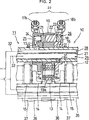
2 eine Querschnittsansicht von einem einlassseitigen Teil eines Zylinderdeaktivierungsmechanismus in derselben Richtung gesehen ist, wie sich die Mittelachse eines Zylinders erstreckt; 2 FIG. 12 is a cross-sectional view seen from an intake side part of a cylinder deactivation mechanism in the same direction as the center axis of a cylinder extends; FIG.
3 eine schematische Darstellung einer Kühlsteuer/regeleinheit ist, welche Kühlmittelzirkulationsdurchgänge umfasst; 3 Fig. 12 is a schematic diagram of a cooling control unit including coolant circulation passages;
4 eine schematische Darstellung einer Kühlsteuer/regeleinheit gemäß einer weiteren Ausführungsform ist; und 4 FIG. 3 is a schematic representation of a cooling control unit according to another embodiment; FIG. and
5 noch eine schematische Darstellung einer Kühlsteuer/regeleinheit gemäß noch einer weiteren Ausführungsform ist. 5 is still a schematic representation of a cooling control / regulating unit according to yet another embodiment.
Nachfolgend wird basierend auf den 1 bis 5 eine Ausführungsform der vorliegenden Erfindung beschrieben.The following is based on the 1 to 5 An embodiment of the present invention is described.
Ein an einem nicht dargestellten Motorfahrzeug angebrachter OHC-Viertaktverbrennungsmotor 1 ist ein Sechszylinderverbrennungsmotor vom Vorne/Hinten-V-Typ, welcher, wie in 1 gezeigt, eine Kurbelwelle (nicht veranschaulicht) umfasst, welche in der Breitenrichtung des Motorfahrzeugs orientiert ist, wie auch eine Zylinderreihe (vordere Bank Bf), welche aus drei Zylindern an der Vorderseite von dem Motorfahrzeugkörper besteht, und einer Zylinderreihe (hintere Bank Br), welche aus den anderen drei Zylindern an der Rückseite von dem Motorfahrzeugkörper besteht, wobei die zwei Zylinderreihen einen eingeschlossenen Winkel von angenähert 60 Grad bilden. Der Hauptkörper von dem OHC-Viertaktverbrennungsmotor 1 von diesem Typ besteht aus: einem Zylinderblock 2; einem Kurbelgehäuse 3, welches integral an der unteren Fläche von dem Zylinderblock 2 angebracht ist; Zylinderköpfen 4 und 4, welche integral jeweils an der Spitze von der Zylinderreihe angebracht sind, welche von dem Zylinderblock 2 in der Längsrichtung des Motorfahrzeugkörpers nach vorne angeordnet ist, und der Spitze von der Zylinderreihe, welche von dem Zylinderblock 2 in der Längsrichtung von dem Motorfahrzeugkörper nach hinten angeordnet ist; und Kopfabdeckungen 5 und 5, welche jeweils die Zylinderköpfe 4 und 4 abdecken.A mounted on a motor vehicle, not shown, OHC four-stroke engine 1 is a front-rear V-type six-cylinder internal combustion engine, which, as in 1 shown, a crankshaft (not illustrated) oriented in the width direction of the motor vehicle, as well as a row of cylinders (front bank Bf) consisting of three cylinders at the front of the motor vehicle body and a row of cylinders (rear bank Br), which consists of the other three cylinders at the rear of the motor vehicle body, the two rows of cylinders forming an included angle of approximately 60 degrees. The main body of the OHC four-stroke internal combustion engine 1 of this type consists of: a cylinder block 2 ; a crankcase 3 integral with the lower surface of the cylinder block 2 is appropriate; cylinder heads 4 and 4 , which are integrally attached respectively at the top of the cylinder row, which from the cylinder block 2 is arranged in the longitudinal direction of the motor vehicle body forward, and the tip of the cylinder bank, which from the cylinder block 2 is arranged rearwardly in the longitudinal direction of the motor vehicle body; and head covers 5 and 5 , which respectively the cylinder heads 4 and 4 cover.
Einlassvorrichtungen, welche Kraftstoffeinspritzventilvorrichtungen und Einlasskammern umfassen, welche hier nicht dargestellt sind, sind in einem Zwischenraum zwischen der vorderen Bank Bf und der hinteren Bank Br von dem OHC-Viertaktverbrennungsmotor 1 angeordnet. Außerdem sind Auspuffrohre, welche hier nicht dargestellt sind, jeweils mit den vorderen und hinteren Außenseiten der Zylinderköpfe 4 und 4 von jeder Bank von der vorderen Bank Bf und der hinteren Bank Br verbunden.Intake devices, which include fuel injection valve devices and intake chambers, which are not shown here, are in a space between the front bank Bf and the rear bank Br of the OHC four-stroke engine 1 arranged. In addition, exhaust pipes, which are not shown here, each with the front and rear outer sides of the cylinder heads 4 and 4 from each bank connected by the front bank Bf and the rear bank Br.
Die drei Zylinder von der vorderen Bank Bf sind alle normal aktivierte Zylinder, wohingegen die drei Zylinder von der hinteren Bank Br alle deaktivierungsprogrammierte Zylinder sind.The three cylinders from the front bank Bf are all normally activated cylinders, whereas the three cylinders from the rear bank Br are all deactivation-programmed cylinders.
Insbesondere ist ein hydraulisch betätigter Zylinderdeaktivierungsschaltmechanismus 20 in einen Ventilmechanismus 10 nur in der hinteren Bank Br von der vorderen Bank Bf und der hinteren Bank Br eingebaut. 2 ist eine Querschnittsansicht, welche zeigt, wie ein Teil von einer Einlassseite von dem Zylinderdeaktivierungsmechanismus 20 aussieht, wenn dieser von der Oberseite des Zylinderkopfs 4 in derselben Richtung betrachtet wird, in der sich die Mittelachse eines der Zylinder erstreckt. In particular, a hydraulically actuated cylinder deactivation switching mechanism 20 in a valve mechanism 10 built only in the rear bank Br from the front bank Bf and the rear bank Br. 2 FIG. 12 is a cross-sectional view showing how a part from an inlet side of the cylinder deactivation mechanism. FIG 20 Looks like this from the top of the cylinder head 4 in the same direction in which the central axis of one of the cylinders extends.
Der Ventilmechanismus 10 ist im inneren einer Ventilkammer 11 angeordnet, welche von dem mit dem oberen Ende des Zylinderblocks 2 verbundenen Zylinderkopf 4 und der mit dem oberen Ende des Zylinderkopfs 4 verbundenen Kopfabdeckung 5 gebildet ist.The valve mechanism 10 is inside a valve chamber 11 arranged, which of the with the upper end of the cylinder block 2 connected cylinder head 4 and the one with the top of the cylinder head 4 connected head cover 5 is formed.
Brennräume sind zwischen dem Zylinderkopf 4 und jedem der Kolben ausgebildet, welche verschiebbar in die jeweiligen Zylinder eingesetzt sind, welche in dem Zylinderblock 2 ausgebildet sind. Einlasskanäle und Auslasskanäle, welche mit ihren entsprechenden Brennräumen in Verbindung stehen, sind in dem Zylinderkopf 4 ausgebildet. Eine Nockenwelle 12, welche drehmäßig einmal für jede halbe Umdrehung der von den Kolben angetriebenen Kurbelwelle angetrieben wird, ist in jeweilige Einsetzlöcher in mehreren Nockenhaltern eingesetzt, welche integral in dem Zylinderkopf 4 in Intervallen in derselben Richtung ausgebildet sind, in der sich die Mittelachse der Nockenwelle 12 erstreckt. Die Nockenwelle 12 ist drehbar durch die Lagerabschnitte gelagert.Combustion chambers are between the cylinder head 4 and each of the pistons slidably fitted in the respective cylinders, which are in the cylinder block 2 are formed. Intake passages and exhaust passages communicating with their respective combustion chambers are in the cylinder head 4 educated. A camshaft 12 , which is rotationally driven once for each half revolution of the crankshaft driven by the pistons, is inserted into respective insertion holes in a plurality of cam holders integral with the cylinder head 4 are formed at intervals in the same direction, in which the central axis of the camshaft 12 extends. The camshaft 12 is rotatably supported by the bearing sections.
In jedem Brennraum werden paarweise vorgesehene Einlassventile und paarweise vorgesehene Auslassventile, welche schwenkbar durch den Zylinderkopf 4 gelagert sind, durch die Nockenwelle 12, die an der Nockenwelle 12 vorgesehenen Nocken 13, 14 und 15, eine Kipphebelwelle 16, schwenkbar von der Kipphebelwelle 16 gelagerte Kipphebel 17, 18 und 19, wie auch dem Ventilmechanismus 10, welcher den Zylinderdeaktivierungsschaltmechanismus 20 umfasst, betätigt. Paarweise vorgesehene Öffnungen der Einlasskanäle, welche dem Brennraum näher sind, und paarweise vorgesehene Öffnungen der Auslasskanäle, welche dem Brennraum näher sind, werden mit ihren eigenen vorbestimmten Steuerzeiten geöffnet und geschlossen.In each combustion chamber are provided in pairs inlet valves and paired exhaust valves, which pivotally through the cylinder head 4 are stored, through the camshaft 12 attached to the camshaft 12 provided cam 13 . 14 and 15 , a rocker arm shaft 16 , pivotable from the rocker shaft 16 mounted rocker arms 17 . 18 and 19 as well as the valve mechanism 10 , which is the cylinder deactivation switching mechanism 20 includes, actuated. Paired ports of the intake ports closer to the combustion chamber and paired ports of the exhaust ports closer to the combustion chamber are opened and closed at their own predetermined timing.
Die Zylinder in der hinteren Bank Br als einem Teil des Verbrennungsmotors 1 sind deaktiviert, während der Motor derart betrieben wird, dass durch eine niedrige Last oder dgl. dem Kraftstoffverbrauch Bedeutung beigemessen wird. Zu diesem Zweck ist der Ventilmechanismus 10 in der hinteren Bank Br mit dem Zylinderdeaktivierungsschaltmechanismus 20 versehen, um die Einlassventile und die Auslassventile geschlossen zu halten, während der Motor arbeitet, wobei die Zylinder in der hinteren Bank deaktiviert sind.The cylinders in the rear bank Br as a part of the internal combustion engine 1 are deactivated while the engine is operated so as to give importance to fuel consumption by a low load or the like. For this purpose, the valve mechanism 10 in the rear bank Br with the cylinder deactivation switching mechanism 20 to keep the intake valves and the exhaust valves closed while the engine is operating, with the cylinders in the rear bank deactivated.
Nachfolgend wird angesichts der 2 hauptsächlich der näher an den Einlassventilen vorgesehene Zylinderdeaktivierungsschaltmechanismus 20 beschrieben.The following will be given the 2 mainly the cylinder deactivation switching mechanism provided closer to the intake valves 20 described.
In jedem Brennraum ist die Nockenwelle 12 versehen mit dem Einlassnocken 13, den paarweise vorgesehenen Deaktivierungsnocken 14, welche an den jeweiligen zwei Seiten von dem Einlassnocken 13 angeordnet sind, wobei der Einlassnocken 13 dazwischen angeordnet ist, den paarweise vorgesehenen Auslassnocken 15, welche an den Seiten der jeweiligen zwei Deaktivierungsnocken 14 angeordnet sind, wobei der Einlassnocken 13 und die Deaktivierungsnocken 14 dazwischen angeordnet sind.In each combustion chamber is the camshaft 12 provided with the intake cam 13 , the pairing deactivation cams 14 , which on the respective two sides of the inlet cam 13 are arranged, wherein the intake cam 13 is arranged in between, the pair provided exhaust cam 15 which are on the sides of the respective two deactivation cams 14 are arranged, wherein the intake cam 13 and the deactivation cams 14 are arranged between them.
Jeder von dem Einlassnocken 13 und den Auslassnocken 15 hat sein eigenes Nockenprofil, welches einen kreisförmigen Basisabschnitt und einen Nasenabschnitt umfasst, welcher einen vorbestimmten Hubbetrag und einen Betätigungswinkel aufweist. Jeder von den Deaktivierungsnocken 14 hat sein eigenes Nockenprofil, welches nur einen kreisförmigen Basisabschnitt umfasst, dessen Radius dem von dem kreisförmigen Basisabschnitt von jedem von den Einlassnocken 13 und den Auslassnocken 15 entspricht. Jeder von den Deaktivierungsnocken 14 hält sein entsprechendes Einlassventil und Auslassventil geschlossen, während der Motor arbeitet, wobei die Zylinder in der hinteren Bank deaktiviert sind.Everyone from the intake cam 13 and the exhaust cam 15 has its own cam profile including a circular base portion and a nose portion having a predetermined lift amount and an operation angle. Each of the deactivation cams 14 has its own cam profile including only a circular base portion whose radius is that of the circular base portion of each of the intake cams 13 and the exhaust cam 15 equivalent. Each of the deactivation cams 14 keeps its corresponding intake valve and exhaust valve closed while the engine is operating, with the cylinders in the rear bank deactivated.
In jedem Brennraum sind die paarweise vorgesehenen Antriebskipphebel 17 und 18 wie auch der zwischen den paarweise vorgesehenen Antriebskipphebeln 17 und 18 angeordnete freie Kipphebel 19 schwenkbar durch die Kipphebelwelle gelagert, welche in jeweilige Einsetzlöcher in mehreren an dem Zylinderkopf 4 durch Bolzen befestigten Kipphebelwellenhalterungen eingesetzt ist.In each combustion chamber are provided in pairs drive rocker arms 17 and 18 as well as between the pair provided driving rocker arms 17 and 18 arranged free rocker arms 19 pivotally supported by the rocker shaft, which in respective insertion holes in a plurality of the cylinder head 4 Inserted by bolt rocker arm shaft mounts is used.
Ein Gleitstück 17a, welches gleitend seinen entsprechenden Deaktivierungsnocken 14 berührt, ist in einem Endabschnitt von dem Antriebskipphebel 17 ausgebildet, wohingegen ein Gleitstück 18a, welches gleitend seinen entsprechenden Deaktivierungsnocken 14 berührt, in einem Endabschnitt von dem Antriebskipphebel 18 ausgebildet ist. Eine Stößelschraube 17b, welche an ihrem entsprechenden Einlassventil anliegt, ist an dem anderen Endabschnitt von dem Antriebskipphebel 17 ausgebildet, wohingegen eine Stößelschraube 18b, welche an ihrem entsprechenden Einlassventil anliegt, in dem anderen Endabschnitt von dem Antriebskipphebel 18 ausgebildet ist.A slider 17a which sliding its corresponding deactivation cam 14 is in an end portion of the drive rocker arm 17 trained, whereas a slider 18a which sliding its corresponding deactivation cam 14 touched, in an end portion of the drive rocker arm 18 is trained. A plunger screw 17b which abuts against its respective inlet valve is at the other end portion of the drive rocker arm 17 trained, whereas a ram screw 18b which abuts against its respective inlet valve, in the other end portion of the drive rocker arm 18 is trained.
Darüber hinaus ist eine Rolle 19a, welche den Auslassnocken 13 rollend berührt, drehbar durch einen Endabschnitt von dem freien Kipphebel 19 gelagert. Der freie Kipphebel 19 ist zu dem Einlassnocken 13 durch eine Feder von einem Totgangmechanismus vorgespannt, welcher von dem Zylinderkopf 4 getragen ist. In addition, a role 19a which the exhaust cam 13 rollingly contacted, rotatable by an end portion of the free rocker arm 19 stored. The free rocker arm 19 is to the inlet cam 13 biased by a spring from a lost motion mechanism, which of the cylinder head 4 worn.
Der Zylinderdeaktivierungsschaltmechanismus 20 ist in einer Weise vorgesehen, dass der Zylinderdeaktivierungsschaltmechanismus 20 sich über die Antriebskipphebel 17 und 18 wie auch den freien Kipphebel 19 erstreckt. Der Zylinderdeaktivierungsschaltmechanismus 20 ist der, welcher es ermöglicht, dass die Antriebskipphebel 17 und 18 mit dem freien Kipphebel 19 verbunden werden und von diesem getrennt werden.The cylinder deactivation switching mechanism 20 is provided in a manner that the cylinder deactivation switching mechanism 20 over the drive rocker arms 17 and 18 as well as the free rocker arm 19 extends. The cylinder deactivation switching mechanism 20 is the one that allows the drive rocker arms 17 and 18 with the free rocker arm 19 be connected and disconnected from it.
Der Zylinderdeaktivierungsschaltmechanismus 20 umfasst: einen Verbindungskolben 21, um es zu ermöglichen, den Antriebskipphebel 17 und den freien Kipphebel 19 miteinander zu verbinden; einen Verbindungsstift 22, um es zu ermöglichen, den Antriebskipphebel 17 und den freien Kipphebel 19 miteinander zu verbinden; einen Freigabekolben 23, um die Bewegung des Verbindungsstifts 22 zu begrenzen und gleichzeitig die Antriebskipphebel 17 und 18 von dem freien Kipphebel 19 zu trennen; eine Rückstellfeder 24, um zu bewirken, dass der Verbindungsstift 22 an dem Verbindungskolben 21 anliegt und gleichzeitig zu bewirken, dass der Freigabestift 23 an dem Verbindungsstift 22 anliegt; eine erste Hydraulikkammer 25, welche in dem Antriebskipphebel 17 ausgebildet ist und welcher Hydraulikfluid zur Bewegung des Verbindungskolbens 21 zugeführt wird, von welcher das Hydraulikfluid abgegeben wird, und welche auch die Rückstellfeder 24 aufnimmt; und eine zweite Hydraulikkammer, welche in dem Antriebskipphebel 18 ausgebildet ist, um den Freigabekolben 23 zu bewegen.The cylinder deactivation switching mechanism 20 includes: a connecting piston 21 To make it possible, the drive rocker arm 17 and the free rocker arm 19 to connect with each other; a connecting pin 22 To make it possible, the drive rocker arm 17 and the free rocker arm 19 to connect with each other; a release piston 23 to the movement of the connecting pin 22 to limit and at the same time the drive rocker arm 17 and 18 from the free rocker arm 19 to separate; a return spring 24 to cause the connector pin 22 on the connecting piston 21 abuts and at the same time to cause the release pin 23 at the connecting pin 22 bears; a first hydraulic chamber 25 , which in the drive rocker arm 17 is formed and which hydraulic fluid for moving the connecting piston 21 is fed, from which the hydraulic fluid is discharged, and which also the return spring 24 receives; and a second hydraulic chamber, which in the drive rocker arm 18 is designed to the release piston 23 to move.
Ein Rohr 27, welches in einen hohlen Abschnitt der zylindrischen Kipphebelwelle 16 eingesetzt ist, teilt den hohlen Abschnitt und ein erster Hydraulikfluiddurchgang 28 wird so zwischen dem Rohr 27 und der Kipphebelwelle 16 ausgebildet, und auch ein zweiter Hydraulikfluiddurchgang 29 wird so in dem hohlen Abschnitt von dem Rohr 27 ausgebildet.A pipe 27 which is in a hollow portion of the cylindrical rocker shaft 16 is inserted divides the hollow portion and a first hydraulic fluid passage 28 so is between the pipe 27 and the rocker arm shaft 16 formed, and also a second hydraulic fluid passage 29 so gets in the hollow section of the pipe 27 educated.
Die erste Hydraulikkammer 25 steht immer mit dem ersten Hydraulikfluiddurchgang 28 durch einen Verbindungsdurchgang 30 in Verbindung, welcher in dem Antriebskipphebel 17 ausgebildet ist. Die zweite Hydraulikkammer 26 steht immer mit dem zweiten Hydraulikfluiddurchgang 29 durch einen Verbindungsdurchgang 31 in Verbindung, welcher in dem Antriebskipphebel 18 und dem Rohr 27 ausgebildet ist.The first hydraulic chamber 25 always stands with the first hydraulic fluid passage 28 through a connection passage 30 in connection, which in the drive rocker arm 17 is trained. The second hydraulic chamber 26 always stands with the second hydraulic fluid passage 29 through a connection passage 31 in connection, which in the drive rocker arm 18 and the tube 27 is trained.
Der erste Hydraulikfluiddurchgang 28 und der zweite Hydraulikfluiddurchgang 29 stehen jeweils durch einen ersten Fluiddurchgang 32 und einen zweiten Fluiddurchgang 33, welche in dem Zylinderkopf 4 ausgebildet sind, mit einer an dem Zylinderkopf 4 angebrachten Hydrauliksteuer/regelventilvorrichtung (nicht dargestellt) in Verbindung.The first hydraulic fluid passage 28 and the second hydraulic fluid passage 29 each through a first fluid passage 32 and a second fluid passage 33 which is in the cylinder head 4 are formed, with one on the cylinder head 4 mounted hydraulic control / regulating valve device (not shown) in conjunction.
Eine Hydraulikdruck-Quelle ist eine Ölpumpe, welche durch den Antrieb des Verbrennungsmotors 1 betrieben wird.A hydraulic pressure source is an oil pump, which by the drive of the internal combustion engine 1 is operated.
Andererseits ist auf der Auslassseite von dem Zylinderkopf ein Ventilbetätigungscharakteristikveränderungsmechanismus an einer Stelle vorgesehen, welche näher zu dem Auslassventil liegt, in einer Weise, dass der Ventilbetätigungscharakteristikveränderungsmechanismus sich über die paarweise vorgesehene Antriebskipphebel 36 und die paarweise vorgesehenen freien Kipphebel 37 erstreckt, welche schwenkbar an der Kipphebelwelle 35 gelagert sind. Der Ventilbetätigungscharakteristikveränderungsmechanismus umfasst: Verbindungskolben, um zu ermöglichen, die Antriebskipphebel 36 jeweils mit den freien Kipphebeln 37 zu verbinden; und Freigabekolben, um die Bewegung der jeweiligen Verbindungskolben zu begrenzen und gleichzeitig die Antriebskipphebel 36 von den jeweiligen freien Kipphebeln 37 zu lösen. Wie der Zylinderdeaktivierungsschaltmechanismus 20 auf der Einlassseite von dem Zylinderkopf werden diese Kolben durch Hydraulikdrücke von den Hydraulikfluiden von dem ersten Hydraulikfluiddurchgang 28 und dem zweiten Hydraulikfluiddurchgang 29 betätigt.On the other hand, on the exhaust side of the cylinder head, a valve-operating characteristic changing mechanism is provided at a position closer to the exhaust valve, in such a manner that the valve-operating characteristic changing mechanism moves via the paired driving rocker arms 36 and the pair provided free rocker arms 37 which pivots on the rocker shaft 35 are stored. The valve operating characteristic changing mechanism includes: connecting pistons for allowing the driving rocker arms 36 each with the free rocker arms 37 connect to; and release pistons to limit the movement of the respective connecting pistons and at the same time the drive rocker arms 36 from the respective free rocker arms 37 to solve. Like the cylinder deactivation switching mechanism 20 On the inlet side of the cylinder head, these pistons are pressurized by hydraulic pressures from the hydraulic fluids from the first hydraulic fluid passage 28 and the second hydraulic fluid passage 29 actuated.
Während der Motor arbeitet, wobei alle Zylinder aktiviert sind, wird bewirkt, dass der erste Hydraulikfluiddurchgang 28 mit einem Hochdruckfluiddurchgang in Verbindung steht durch den ersten Fluiddurchgang 32 von der Hydrauliksteuer/regelventilvorrichtung, welche gemäß dem Betriebszustand des Motorfahrzeugs gesteuert/geregelt wird, und der Druck des Hydraulikfluids wird so höher. Andererseits wird bewirkt, dass der zweite Hydraulikfluidurchgang 29 mit einem Drainagefluiddurchgang durch den zweiten Fluiddurchgang 33 in Verbindung steht, und der Druck des Hydraulikfluids wird so niedriger.While the engine is operating, with all cylinders activated, the first hydraulic fluid passage is caused to be 28 communicating with a high pressure fluid passage through the first fluid passage 32 from the hydraulic control valve device which is controlled according to the operating state of the motor vehicle, and the pressure of the hydraulic fluid becomes higher. On the other hand, it causes the second hydraulic fluid passage 29 with a drainage fluid passage through the second fluid passage 33 communicates, and the pressure of the hydraulic fluid is thus lower.
Als Ergebnis bewirkt die Druckdifferenz zwischen der ersten Hydraulikkammer 25 und der zweiten Hydraulikkammer 26, dass der Verbindungskolben 21 den Verbindungskolben 22 und den Freigabekolben 23 drückt, und auch somit Positionen der Anlagefläche zwischen dem Verbindungskolben 21 und dem Verbindungsstift 22 in dem freien Kipphebel 19 und der Anlagefläche zwischen dem Verbindungsstift 22 und dem Freigabekolben 23 in dem Antriebskipphebel 18. Folglich werden die Antriebskipphebel 17 und 18 mit dem freien Kipphebel 19 verbunden. Dadurch werden die jeweiligen Schwenkbewegungen der Antriebskipphebel 17 und 18 durch das Nockenprofil des Einlassnockens 13 begrenzt. Dies öffnet und schließt die Einlassventile mit ihren jeweiligen vorbestimmten Zeiteinstellungen mit ihren jeweiligen Hubbeträgen. Entsprechend öffnet und schließt dies die Auslassventile mit ihren jeweiligen vorbestimmten Zeiteinstellungen mit ihren jeweiligen Hubbeträgen.As a result, the pressure difference between the first hydraulic chamber causes 25 and the second hydraulic chamber 26 that the connecting piston 21 the connecting piston 22 and the release piston 23 pushes, and thus also positions of the contact surface between the connecting piston 21 and the connecting pin 22 in the free rocker arm 19 and the contact surface between the connecting pin 22 and the release piston 23 in the drive rocker arm 18 , Consequently, the drive rocker arms 17 and 18 with the free rocker arm 19 connected. This will be the respective Pivoting movements of the drive rocker arms 17 and 18 through the cam profile of the intake cam 13 limited. This opens and closes the intake valves at their respective predetermined time settings with their respective lift amounts. Accordingly, this opens and closes the exhaust valves at their respective predetermined time settings with their respective lift amounts.
Während der Motor arbeitet, wobei die Zylinder in der hinteren Bank deaktiviert sind, wird außerdem bewirkt, dass der erste Hydraulikfluiddurchgang 28 durch den ersten Fluiddurchgang 32 von der Hydrauliksteuer/regelventilvorrichtung mit dem Drainagefluiddurchgang in Verbindung steht, und der Druck des Hydraulikfluids wird so niedriger. Andererseits wird bewirkt, dass der zweite Hydraulikfluiddurchgang 29 mit dem Hochdruckfluiddurchgang durch den zweiten Fluiddurchgang 33 in Verbindung steht, und der Druck des Hydraulikfluids wird so höher.In addition, while the engine is operating with the cylinders in the rear bank deactivated, the first hydraulic fluid passage is also caused to be actuated 28 through the first fluid passage 32 from the hydraulic control valve device communicates with the drainage fluid passage, and the pressure of the hydraulic fluid becomes lower. On the other hand, the second hydraulic fluid passage is caused to be caused 29 with the high pressure fluid passage through the second fluid passage 33 communicates, and the pressure of the hydraulic fluid is higher.
Als Ergebnis wird der Hydraulikdruck in der ersten Hydraulikkammer 25 niedriger, wohingegen der Hydraulikdruck in der zweiten Hydraulikkammer 26 hoher wird. Beginnend mit dem in 2 gezeigten Zustand, bewirkt die Druckdifferenz zwischen der ersten Hydraulikkammer 25 und der zweiten Hydraulikkammer 26 folglich, dass der Freigabekolben 23 den Verbindungskolben 21 und den Verbindungsstift 22 drückt. Somit wird die Anlagefläche zwischen dem Verbindungskolben 21 und dem Verbindungsstift 22 zwischen dem Antriebskipphebel 17 und dem freien Kipphebel 19 angeordnet und die Anlagefläche zwischen dem Verbindungsstift 22 und dem Freigabekolben 23 wird zwischen dem Antriebskipphebel 17 und dem freien Kipphebel 19 angeordnet. Folglich wird der Antriebskipphebel 17 von dem freien Kipphebel 19 gelöst und der Antriebskipphebel 18 wird von dem freien Kipphebel 19 gelöst.As a result, the hydraulic pressure in the first hydraulic chamber becomes 25 lower, whereas the hydraulic pressure in the second hydraulic chamber 26 becomes higher. Starting with the in 2 shown state, causes the pressure difference between the first hydraulic chamber 25 and the second hydraulic chamber 26 consequently, that the release piston 23 the connecting piston 21 and the connecting pin 22 suppressed. Thus, the contact surface between the connecting piston 21 and the connecting pin 22 between the drive rocker arm 17 and the free rocker arm 19 arranged and the contact surface between the connecting pin 22 and the release piston 23 is between the drive rocker arm 17 and the free rocker arm 19 arranged. Consequently, the drive rocker arm 17 from the free rocker arm 19 solved and the drive rocker arm 18 is from the free rocker arm 19 solved.
Dadurch werden die Schwenkbewegungen von den Antriebskipphebeln 17 und 18 jeweils durch die Profile der Deaktivierungsnocken 14 begrenzt. Folglich wird das Einlassventil geschlossen und das Auslassventil wird entsprechend geschlossen. Somit werden die Zylinder deaktiviert.As a result, the pivoting movements of the drive rocker arms 17 and 18 each through the profiles of the deactivation cam 14 limited. As a result, the intake valve is closed and the exhaust valve is closed accordingly. Thus, the cylinders are deactivated.
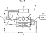
Der Verbrennungsmotor vom Vorne/Hinten-V-Typ mit der vorderen Bank Bf, welche die normal aktivierten Zylinder hat, und der hinteren Bank Br, welche die deaktivierungsprogrammierten Zylinder hat, hat eine Kühlsteuer/regeleinheit 40, welche Kühlmittelzirkulationsdurchgänge umfasst, wie durch eine schematische Darstellung in 3 gezeigt ist.The front-rear V-type internal combustion engine having the front bank Bf having the normally-activated cylinders and the rear bank Br having the deactivation-programmed cylinders has a cooling control unit 40 comprising coolant circulation passages as represented by a schematic in FIG 3 is shown.
Ein Normal-Aktivierter-Zylinder-Wasserkühlmantel Wf, welcher zusätzlich als ein Kühlmitteldurchgang fungiert, ist um die Zylinderbohrungen und Brennräume in dem Zylinderblock 2 und dem Zylinderkopf 4 auf der Seite der vorderen Bank Bf ausgebildet, welche die normal aktivierten Zylinder hat. Entsprechend ist ein Deaktivierungsprogrammierter-Zylinder-Wasserkühlmantel Wr, welcher zusätzlich als ein Kühlmitteldurchgang fungiert, um die Zylinderbohrungen und die Brennräume in dem Zylinderblock 2 und dem Zylinderkopf 4 auf der Seite der hinteren Bank Br ausgebildet, welche die deaktivierungsprogrammierten Zylinder hat.A normal-activated-cylinder water cooling jacket Wf, which additionally functions as a coolant passage, is around the cylinder bores and combustion chambers in the cylinder block 2 and the cylinder head 4 formed on the side of the front bank Bf, which has the normally activated cylinder. Accordingly, a deactivation programmed cylinder water jacket Wr, which additionally functions as a refrigerant passage, is the cylinder bores and the combustion chambers in the cylinder block 2 and the cylinder head 4 formed on the side of the rear bank Br, which has the deactivation-programmed cylinder.
Das von einer Wasserpumpe 41 geförderte Kühlmittel strömt in den Normal-Aktivierter-Zylinder-Wasserkühlmantel Wf von seiner Einlassöffnung, nachdem er einen Auslassdurchgang 42 passiert, und zirkuliert nachfolgend durch den Normal-Aktivierter-Zylinder-Wasserkühlmantel Wf, um danach aus dem Normal-Aktivierter-Zylinder-Wasserkühlmantel Wf durch seine Auslassöffnung auszuströmen. Nach dem Ausströmen aus dem Wasserkühlmantel strömt das Kühlmittel in den Verbindungsdurchgang 43, durch welchen die Auslassöffnung von dem Normal-Aktivierter-Zylinder-Wasserkühlmantel und die Einlassöffnung von einem Deaktivierungsprogrammierter-Zylinder-Wasserkühlmantel Wr miteinander in Verbindung stehen.That of a water pump 41 delivered coolant flows into the normally-activated-cylinder water cooling jacket Wf from its inlet port after having an exhaust passage 42 passes, and subsequently circulates through the normal-activated-cylinder water cooling jacket Wf to then flow out of the normal-activated-cylinder water jacket Wf through its outlet port. After flowing out of the water cooling jacket, the coolant flows into the connection passage 43 through which the outlet port of the normally-activated cylinder water jacket and the inlet port of a deactivation-programmed cylinder water jacket Wr communicate with each other.
Ein Auslassdurchgang 44 erstreckt sich von der Auslassöffnung von dem Deaktivierungsprogrammierter-Zylinder-Wasserkühlmantel Wr zu einem Thermostat 45 und ist so mit dem Thermostat 45 verbunden.An outlet passage 44 extends from the outlet port of the deactivation programmed cylinder water jacket Wr to a thermostat 45 and is like that with the thermostat 45 connected.
Ein Wasserzuleitungsrohr 46 erstreckt sich von dem Thermostat 45 zu einem Kühler 47. Ein Einlassrohr 48 erstreckt sich von dem Kühler 47 zu der Wasserpumpe 41 und ist so mit der Wasserpumpe 41 verbunden.A water supply pipe 46 extends from the thermostat 45 to a cooler 47 , An inlet pipe 48 extends from the radiator 47 to the water pump 41 and is like that with the water pump 41 connected.
Zusätzlich erstreckt sich ein Bypassrohr 49, durch welches die Wasserpumpe 41 einen Teil des Kühlmittels anstelle über den Kühler 47 direkt aufnimmt, von dem Thermostat 45 zu dem Einlassrohr 48 und ist so mit dem Einlassrohr 48 verbunden.In addition, a bypass tube extends 49 through which the water pump 41 a part of the coolant instead of the cooler 47 picks up directly from the thermostat 45 to the inlet pipe 48 and is like that with the inlet pipe 48 connected.
Ferner hat diese Kühlsteuer/regeleinheit 40 ein Ableitungssteuer/regelventil 51, welches in der Mitte von dem Verbindungsdurchgang 43 vorgesehen ist. Ein Bypassdurchgang 52, welcher von dem Ableitungssteuer/regelventil 51 abzweigt, ist mit dem Auslassdurchgang 44 von dem Deaktivierungsprogrammierter-Zylinder-Wasserkühlmantel Wr verbunden, während er den Deaktivierungsprogrammierter-Zylinder-Wasserkühlmantel Wr umgeht.Furthermore, this cooling control unit has 40 a drain control valve 51 which is in the middle of the connection passage 43 is provided. A bypass passage 52 which is from the drain control valve 51 Branches is with the outlet passage 44 from the deactivation programmed cylinder water jacket Wr while bypassing the deactivation programmed cylinder water jacket Wr.
Das Ableitungssteuer/regelventil 51 teilt den Kühlmittelfluss von dem Normal-Aktivierter-Zylinder-Wasserkühlmantel Wf in ein Teil von dem Kühlmittel, welches in den Deaktivierungsprogrammierter-Zylinder-Wasserkühlmantel Wr strömt, und den anderen Teil des Kühlmittels, welcher in den Bypassdurchgang 52 strömt. Das Ableitungssteuer/regelventil 51 kann das Ableitungsverhältnis zwischen der Strömung des Kühlmittels in dem Deaktivierungsprogrammierter-Zylinder-Wasserkühlmantel Wr und der Strömung des Kühlmittels in dem Bypassdurchgang 52 ungeachtet der jeweiligen Drücke von den zwei Leitungen linear stufenlos einstellen. Von einer ECU (elektronische Steuer/Regeleinheit) 53 gesteuert/geregelt, stellt das Ableitungssteuer/regelventil 51 das Ableitungsverhältnis ein.The drain control valve 51 divides the flow of coolant from the normally-activated cylinder water jacket Wf into a portion of the coolant flowing into the deactivation-programmed cylinder water jacket Wr and the other portion of the coolant entering the bypass passage 52 flows. The deduction tax / control valve 51 For example, the derivative ratio between the flow of the coolant in the deactivation programmed cylinder water jacket Wr and the flow of the coolant in the bypass passage 52 regardless of the pressures of the two lines linearly adjustable. From an ECU (electronic control unit) 53 controlled / regulated, provides the derivative control valve 51 the derivative ratio.
Durch eine Überwachung des Betriebszustands von dem Verbrennungsmotor 1 treibt und steuert/regelt die ECU 53 das Ableitungssteuer/regelventil 51 gemäß dem Betriebszustand und stellt somit das Ableitungsverhältnis ein.By monitoring the operating state of the internal combustion engine 1 drives and controls the ECU 53 the discharge control valve 51 according to the operating condition and thus sets the derivative ratio.
Wenn das Verhältnis der Strömung in dem Bypassdurchgang 52 auf 0 (null) gesetzt ist, strömt das von der Auslassöffnung von dem Normal-Aktivierter-Zylinder-Wasserkühlmantel Wf in den Verbindungsdurchgang 43 abgegebene Kühlmittel vollständig in den Deaktivierungsprogrammierter-Zylinder-Wasserkühlmantel Wr. Wenn umgekehrt das Verhältnis der Strömung in dem Deaktivierungsprogrammierter-Zylinder-Wasserkühlmantel Wr auf 0 (null) gesetzt ist, strömt das von der Auslassöffnung von dem Normal-Aktivierter-Zylinder-Wasserkühlmantel Wf in den Verbindungsdurchgang 43 abgegebene Kühlmittel vollständig in den Bypassdurchgang 52. Das Ableitungsverhältnis zwischen dem in dem Deaktivierungsprogrammierter-Zylinder-Wasserkühlmantel Wr strömenden Kühlmittel und dem in dem Bypassdurchgang 52 strömenden Kühlmittel kann zwischen den vorangehenden zwei Fällen frei eingestellt werden.If the ratio of the flow in the bypass passage 52 is set to 0 (zero), flows from the outlet port of the normal-activated-cylinder water jacket Wf into the communication passage 43 Completely discharged coolant into the deactivation-programmed cylinder water jacket Wr. Conversely, if the ratio of the flow in the deactivation programmed-cylinder water jacket Wr is set to 0 (zero), that flows from the outlet port of the normal-activated-cylinder water jacket Wf into the communication passage 43 completely discharged coolant into the bypass passage 52 , The derivative ratio between the coolant flowing in the deactivation-programmed cylinder water jacket Wr and that in the bypass passage 52 flowing coolant can be freely adjusted between the previous two cases.
Während der Verbrennungsmotor 1 aufgewärmt wird und während das Motorfahrzeug normal fährt, wird der Verbrennungsmotor 1 derart gesteuert/geregelt, dass der Verbrennungsmotor 1 so betrieben werden kann, dass die deaktivierungsprogrammierten Zylinder in der hinteren Bank Br durch den Zylinderdeaktivierungsschaltmechanismus 20 deaktiviert sind und nur die normal aktivierten Zylinder in der vorderen Bank Bf aktiviert sind. Während es erforderlich ist, dass der Verbrennungsmotor 1 eine Kraft ausgibt, welche nicht kleiner als eine vorbestimmte Kraft ist, wird der Verbrennungsmotor 1 derart gesteuert/geregelt, dass der Verbrennungsmotor 1 betrieben werden kann, wobei alle Zylinder aktiviert sind.While the internal combustion engine 1 is warmed up and while the motor vehicle is running normally, the internal combustion engine 1 controlled / regulated so that the internal combustion engine 1 can be operated so that the deactivation-programmed cylinder in the rear bank Br through the cylinder deactivation switching mechanism 20 are deactivated and only the normally activated cylinders in the front bank Bf are activated. While it is required that the internal combustion engine 1 outputs a force which is not smaller than a predetermined force becomes the internal combustion engine 1 controlled / regulated so that the internal combustion engine 1 can be operated with all cylinders are activated.
Während der Verbrennungsmotor 1 aufgewärmt wird, unmittelbar nachdem er gestartet ist, werden nur die normal aktivierten Zylinder in der vorderen Bank Bf aktiviert, wobei die übrigen Zylinder in der hinteren Bank Br deaktiviert sind. In diesem Fall bewirkt die Kühlsteuer/Regeleinheit 40, welche den vorangehenden einfachen Aufbau hat, dass das Ableitungssteuer/regelventil 51 das Verhältnis der Strömung in dem Deaktivierungsprogrammierter-Zylinder-Wasserkühlmantel Wr auf 0 (null) einstellt und das Verhältnis der Strömung in dem Bypassdurchgang 52 auf 100% einstellt und bewirkt so, dass das gesamte Kühlmittel, welches den Normal-Aktivierter-Zylinder-Wasserkühlmantel Wf nach der Förderung von der Wasserpumpe 41 passiert, zu dem Bypassdurchgang 52 strömt, welcher von dem Verbindungsdurchgang 43 abzweigt und welcher den Deaktivierungsprogrammierter-Zylinder-Wasserkühlmantel Wr umgeht. Als Ergebnis erreicht das so erwärmte Kühlmittel das Thermostat 45. Das Thermostat 45 schließt das Ventil von dem zu dem Kühler 47 führenden Wasserzuleitungsrohr 46 und bewirkt so, dass das von dem Verbrennungsmotor 1 kommende Kühlmittel direkt über das Bypassrohr 49 in die Wasserpumpe 41 aufgenommen wird, anstelle über den Kühler 47.While the internal combustion engine 1 is warmed up immediately after it is started, only the normally activated cylinders are activated in the front bank Bf, with the remaining cylinders in the rear bank Br being deactivated. In this case, the cooling control unit causes 40 having the foregoing simple structure that the derivative control valve 51 Sets the ratio of the flow in the deactivation programmed-cylinder water jacket Wr to 0 (zero) and the ratio of the flow in the bypass passage 52 to 100% and thus causes all the coolant containing the Normal Activated Cylinder Water Cooling Jacket Wf to be pumped from the water pump 41 happens, to the bypass passage 52 which flows from the connection passage 43 which bypasses the deactivation programmed cylinder water jacket Wr. As a result, the thus heated coolant reaches the thermostat 45 , The thermostat 45 closes the valve from that to the radiator 47 leading water supply pipe 46 and thus causes that of the internal combustion engine 1 Coming coolant directly over the bypass tube 49 in the water pump 41 is taken, instead of the cooler 47 ,
Insgesamt zirkuliert das Kühlmittel nur durch den Normal-Aktivierter-Zylinder-Wasserkühlmantel Wf und den Bypassdurchgang 52, ohne den Kühler 47 zu passieren. Dies ermöglicht es, die Aufwärmung des Verbrennungsmotors zu beschleunigen.Overall, the coolant circulates only through the normally-activated cylinder water jacket Wf and the bypass passage 52 without the cooler 47 to happen. This makes it possible to accelerate the warm-up of the internal combustion engine.
Während das Motorfahrzeug normal fährt, wird der Verbrennungsmotor 1 in Betrieb gehalten, wobei nur die normal aktivierten Zylinder in der vorderen Bank Bf aktiviert sind, mit dem Ziel, Wert auf den Kraftstoffverbrauch zu legen. In diesem Fall schließt das Thermostat 45 das Ventil von dem Bypassrohr 49 aber öffnet das Ventil von dem Wasserzuleitungsrohr 46, welches zu dem Kühler 47 führt. Aus diesem Grund wird das Kühlmittel, welches von dem Verbrennungsmotor 1 zu dem Thermostat 45 strömt, gekühlt, während es den Kühler 47 passiert, und wird nachfolgend dem Normal-Aktivierter-Zylinder-Wasserkühlmantel Wf zugeführt. Dies ermöglicht es, nur die vordere Bank Bf von dem Verbrennungsmotor 1 effizient zu kühlen.While the motor vehicle is driving normally, the internal combustion engine 1 kept in operation, with only the normally activated cylinders are activated in the front bank Bf, with the aim of emphasizing fuel consumption. In this case, the thermostat closes 45 the valve from the bypass tube 49 but opens the valve from the water supply pipe 46 leading to the radiator 47 leads. For this reason, the coolant, which comes from the internal combustion engine 1 to the thermostat 45 flows, cooled, while it is the radiator 47 passes, and is subsequently supplied to the normal-activated-cylinder water jacket Wf. This allows only the front bank Bf of the internal combustion engine 1 to cool efficiently.
Nachdem das Aufwärmen beendet ist, wobei die Temperatur des Kühlmittels in dem Normal-Aktivierter-Zylinder-Wasserkuhlmantel Wf auf eine vorbestimmte Temperatur angestiegen ist, wird das Ableitungssteuer/regelventil 51 gesteuert/geregelt, damit das Kühlmittel nach dem Passieren des Normal-Aktivierter-Zylinder-Wasserkühlmantels Wf in einer adäquaten Menge in den Deaktivierungsprogrammierter-Zylinder-Wasserkühlmantel Wr strömen sollte, und zwar derart, dass die Menge nicht erlauben sollte, dass die Temperatur des Kühlmittels in dem Normal-Aktivierter-Zylinder-Wasserkühlmantel Wf unter eine vorbestimmte unterste Kühlmitteltemperatur fällt.After the warm-up is finished with the temperature of the coolant in the normal-activated-cylinder water jacket Wf rising to a predetermined temperature, the purge control valve becomes 51 in order for the coolant to flow into the deactivation programmed cylinder water jacket Wr after passage of the normally-activated cylinder water jacket Wf in an adequate amount such that the amount should not allow the temperature of the coolant to flow in the normally-activated cylinder water jacket Wf falls below a predetermined lowest coolant temperature.
Als Ergebnis strömt die adäquate Menge des Kühlmittels, welches den Normal-Aktivierter-Zylinder-Wasserkühlmantel Wf passiert hat, in den Deaktivierungsprogrammierter-Zylinder-Wasserkühlmantel Wr und die deaktivierungsprogrammierten Zylinder in der hinteren Bank Bf, welche gegenwärtig nicht aktiviert sind, werden aufgewärmt gehalten. Dadurch ist die Kühlsteuer/regeleinheit 40 in der Lage, zu verhindern, dass der Verbrennungsmotor 1 unvollständig aufgewärmt ist, und folglich die Fahr-/Antriebszustände reibungslos zu schalten, wenn der Verbrennungsmotor zu einem Betriebszustand zurückkehrt, bei dem alle Zylinder aktiviert sind.As a result, the adequate amount of refrigerant that has passed through the normally-activated cylinder water jacket Wf flows into the deactivation-programmed cylinder. Water-cooling jacket Wr and the deactivated-programmed cylinders in the rear bank Bf, which are not currently activated, are kept warmed up. This is the cooling control unit 40 able to prevent the internal combustion engine 1 is incompletely warmed up, and thus to smoothly switch the drive / drive states when the engine returns to an operating state in which all the cylinders are activated.
Während alle Zylinder aktiviert sind, steuert/regelt die Kühlsteuer/regeleinheit 40 das Ableitungssteuer/regelventil 51, damit das Kühlmittel nach dem Passieren des Normal-Aktivierter-Zylinder-Wasserkühlmantels Wf in den Deaktivierungsprogrammierter-Zylinder-Wasserkühlmantel Wr strömen sollte, ohne den Bypassdurchgang 52 zu passieren. Dies ermöglicht es, alle Zylinder effizient zu kühlen.While all cylinders are activated, the cooling control unit controls 40 the discharge control valve 51 to allow the coolant to flow into the deactivation programmed cylinder water jacket Wr after passing the normally-activated cylinder water jacket Wf, without the bypass passage 52 to happen. This makes it possible to efficiently cool all cylinders.
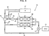
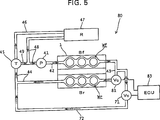
Als Nächstes erfolgt eine Beschreibung einer Kühlsteuer/regeleinheit 70 gemäß einer weiteren Ausführungsform basierend auf einer in 4 gezeigten schematischen Darstellung.Next, a description will be given of a cooling control unit 70 according to another embodiment based on a in 4 shown schematic representation.
Die Konfiguration dieser Kühlsteuer/regeleinheit 70 ist dieselbe wie die der in 3 gezeigten Kühlsteuer/regeleinheit 40 mit der Ausnahme, dass die Konfiguration des Bypassdurchgangs von der Kühlsteuer/regeleinheit 70 von der von dem Bypassdurchgang der Kühlsteuer/regeleinheit 40 verschieden ist. Eine Beschreibung erfolgt, indem Elemente der Kühlsteuer/regeleinheit 70, welche denen der Kühlsteuer/regeleinheit 40 entsprechen, mit denselben Bezugszahlen wie jenen von der Kühlsteuer/regeleinheit 40 bezeichnet werden.The configuration of this cooling control unit 70 is the same as the one in 3 shown cooling control unit 40 with the exception that the configuration of the bypass passage from the cooling control unit 70 from that of the bypass passage of the cooling control unit 40 is different. A description is given by elements of the cooling control unit 70 which those of the cooling control unit 40 with the same reference numbers as those of the cooling control unit 40 be designated.
Es ist ein Bypassdurchgang 72 ausgebildet, welcher von der Mitte von dem Verbindungsdurchgang 43 abzweigt, durch welchen der Normal-Aktivierter-Zylinder-Wasserkühlmantel Wf und der Deaktivierungsprogrammierter-Zylinder-Wasserkühlmantel Wr miteinander in Verbindung stehen, wobei der Bypassdurchgang 72 den Deaktivierungsprogrammierter-Zylinder-Wasserkühlmantel Wr umgeht. Der Bypassdurchgang 72 ist mit dem Auslassdurchgang 44 von dem Deaktivierungsprogrammierter-Zylinder-Wasserkühlmantel Wr verbunden. Dieser Bypassdurchgang 72 umfasst ein Durchflussrateneinstellventil 71, welches in der Mitte des Bypassdurchgangs 72 vorgesehen ist. Das Durchflussrateneinstellventil 71 wird durch eine ECU 73 gesteuert/geregelt.It is a bypass passage 72 formed, which from the center of the connection passage 43 through which the normal-activated-cylinder water jacket Wf and the deactivation-programmed cylinder water jacket Wr communicate with each other, the bypass passage 72 bypasses the deactivation programmed cylinder water jacket Wr. The bypass passage 72 is with the outlet passage 44 from the deactivation programmed cylinder water jacket Wr. This bypass passage 72 includes a flow rate adjustment valve 71 , which is in the middle of the bypass passage 72 is provided. The flow rate adjustment valve 71 is through an ECU 73 controlled / regulated.
Wenn das Durchflussrateneinstellventil 71 vollständig geschlossen ist, ist das gesamte von der Auslassöffnung von dem Normal-Aktivierter-Zylinder-Wasserkühlmantel Wf an den Verbindungsdurchgang 43 abgegebene Kühlmittel dafür bestimmt, in den Deaktivierungsprogrammierter-Zylinder-Wasserkühlmantel Wr zu strömen. Die Einstellung der Durchflussrate von in den Bypassdurchgang 72 strömenden Kühlmittel durch das Öffnen des Durchflussrateneinstellventils 71 bedeutet die Einstellung der Durchflussrate von Kühlmittel, welches von dem in den Bypassdurchgang 72 strömenden Kühlmittels abzweigt, welches somit durch den deaktivierungsprogrammierten Zylinder zirkuliert, nachdem es in den Deaktivierungsprogrammierter-Zylinder-Wasserkühlmantel Wr geströmt ist.When the flow rate adjustment valve 71 is completely closed, all of the outlet opening from the normal-activated-cylinder water jacket Wf to the connection passage 43 discharged coolant intended to flow into the deactivation programmed cylinder water jacket Wr. The adjustment of the flow rate in the bypass passage 72 flowing coolant through the opening of the flow rate adjustment valve 71 means the adjustment of the flow rate of coolant, which of the in the bypass passage 72 flowing coolant, thus circulating through the deactivation programmed cylinder after having flowed into the deactivation programmed cylinder water jacket Wr.
Ähnlich wie der Verbrennungsmotor 1 gemäß der vorangehenden Ausführungsform wird der Verbrennungsmotor 1 gemäß der vorliegenden Ausführungsform derart gesteuert/geregelt, dass der deaktivierungsprogrammierte Zylinder in der hinteren Bank Br durch den Zylinderdeaktivierungsschaltmechanismus 20 deaktiviert werden sollte, wobei nur die normal aktivierten Zylinder in der vorderen Bank Bf aktiviert sind, während der Verbrennungsmotor 1 aufgewärmt wird und während das Motorfahrzeug normal fährt, und auch derart, dass alle Zylinder aktiviert werden sollten, während es erforderlich ist, dass der Verbrennungsmotor 1 eine Kraft ausgibt, welche nicht kleiner als eine vorbestimmte Kraft ist.Similar to the combustion engine 1 According to the foregoing embodiment, the internal combustion engine 1 According to the present embodiment, controlled / regulated such that the deactivation-programmed cylinder in the rear bank Br by the cylinder deactivation switching mechanism 20 should be disabled, with only the normally activated cylinders in the front bank Bf are activated while the internal combustion engine 1 is warmed up and while the motor vehicle is running normally, and also so that all cylinders should be activated while it is necessary for the internal combustion engine 1 outputs a force which is not less than a predetermined force.
Während das Motorfahrzeug normal fährt, schließt das Thermostat 45 das Ventil von dem Bypassrohr 49, aber öffnet das Ventil von dem Wasserzuleitungsrohr 46, welches zu dem Kühler 47 führt. Das Kühlmittel, welches von dem Verbrennungsmotor 1 an das Thermostat 45 abgegeben wurde, wird gekühlt, während es den Kühler 47 passiert und wird nachfolgend dem Normal-Aktivierter-Zylinder-Wasserkühlmantel Wf zugeführt. Dies ermöglicht es, nur die vordere Bank Bf von dem Verbrennungsmotor 1 effizient zu kühlen.While the motor vehicle is moving normally, the thermostat closes 45 the valve from the bypass tube 49 but opens the valve from the water supply pipe 46 leading to the radiator 47 leads. The coolant coming from the combustion engine 1 to the thermostat 45 is discharged, it is cooled while it is the radiator 47 happens and is subsequently supplied to the normal-activated-cylinder water jacket Wf. This allows only the front bank Bf of the internal combustion engine 1 to cool efficiently.
Nachdem die Temperatur des in dem Normal-Aktivierter-Zylinder-Wasserkühlmantel Wf strömenden Kühlmittels auf eine vorbestimmte Temperatur ansteigt, wird das Durchflussrateneinstellventil 71 derart gesteuert/geregelt, dass ein Teil des Kühlmittels nach dem Passieren des Normal-Aktivierter-Zylinder-Wasserkühlmantels Wf in einer adäquaten Menge in den Bypassdurchgang 72 strömen sollte, und zwar derart, dass die Menge nicht erlauben sollte, dass die Temperatur des in dem Normal-Aktivierter-Zylinder-Wasserkühlmantels Wf strömenden Kühlmittels unter eine vorbestimmte niedrigste Kühlmitteltemperatur fällt.After the temperature of the coolant flowing in the normal-activated-cylinder water jacket Wf increases to a predetermined temperature, the flow rate adjustment valve becomes 71 controlled such that a portion of the coolant after passing through the normal-activated-cylinder water cooling jacket Wf in an adequate amount in the bypass passage 72 should flow such that the amount should not allow the temperature of the coolant flowing in the normal-activated-cylinder water jacket Wf to fall below a predetermined lowest coolant temperature.
Als Ergebnis strömt die adäquate Menge des Kühlmittels, welches den Normal-Aktivierter-Zylinder-Wasserkühlmantel Wf passiert hat, in den Deaktivierungsprogrammierter-Zylinder-Wasserkühlmantel Wr und die deaktivierungsprogrammierten Zylinder in der hinteren Bank Bf, welche gegenwärtig nicht aktiviert sind, werden erwärmt gehalten. Dadurch ist die Kühlsteuer/regeleinheit 70 in der Lage, zu verhindern, dass der Verbrennungsmotor 1 unvollständig aufgewärmt ist, wenn der Verbrennungsmotor zu einem Betriebszustand zurückkehrt, bei dem alle Zylinder aktiviert sind.As a result, the adequate amount of the coolant having passed the normal-activated-cylinder water jacket Wf flows into the deactivation-programmed cylinder water jacket Wr and the deactivation-programmed cylinders in the rear bank Bf, which are not currently activated, are kept heated. This is the cooling control unit 70 able to prevent the internal combustion engine 1 is incompletely warmed up when the internal combustion engine returns to an operating condition in which all cylinders are activated.
Während alle Zylinder aktiviert sind, wird das Durchflussrateneinstellventil 71 in einer solchen Weise gesteuert/geregelt, dass das Kühlmittel nach dem Passieren des Normal-Aktivierter-Zylinder-Wasserkühlmantel Wf in den Deaktivierungsprogrammierter-Zylinder-Wasserkühlmantel Wr strömen sollte, ohne den Bypassdurchgang 72 zu passieren. Diese Steuerung/Regelung ermöglicht es, alle Zylinder effizient zu kühlen.While all cylinders are activated, the flow rate adjustment valve becomes 71 controlled in such a manner that the refrigerant should flow into the deactivation programmed cylinder water jacket Wr after passing the normal-activated-cylinder water jacket Wf, without the bypass passage 72 to happen. This control allows all cylinders to be cooled efficiently.
Als Nächstes wird ein Beispiel einer Kühlsteuer/regeleinheit 80, welche zusätzlich zu dem in der Kühlsteuer/regeleinheit 70 enthaltenen Durchflussrateneinstellventil 71 ein zweites Durchflussrateneinstellventil 81 umfasst, welches an einer Stelle stromabwärts von einem Abzweigungsabschnitt, an welchem der Bypassdurchgang 72 von dem Verbindungsdurchgang 43 abzweigt, vorgesehen ist, in 5 gezeigt und beschrieben.Next, an example of a cooling control unit will be described 80 in addition to that in the cooling control unit 70 contained flow rate adjustment valve 71 a second flow rate adjustment valve 81 comprising, at a location downstream of a branch portion, at which the bypass passage 72 from the connection passage 43 branches, is provided in 5 shown and described.
In dieser Ausführungsform wird das Durchflussrateneinstellventil 71 als ein ”erstes Durchflussrateneinstellventil 71” bezeichnet. Eine ECU 83 steuert/regelt jeweils die Antriebe von dem ersten Durchflussrateneinstellventil 71 und dem neu hinzugefügten zweiten Durchflussrateneinstellventil 81.In this embodiment, the flow rate adjusting valve becomes 71 as a "first flow rate adjustment valve 71 " designated. An ECU 83 controls each of the drives from the first flow rate adjustment valve 71 and the newly added second flow rate adjustment valve 81 ,
Es sollte angemerkt werden, dass wie der Verbrennungsmotor 1 jeweils gemäß den vorangehenden Ausführungsformen der Verbrennungsmotor 1 gemäß der vorliegenden Ausführungsform derart gesteuert/geregelt wird, dass die deaktivierungsprogrammierten Zylinder in der hinteren Bank Br durch den Zylinderdeaktivierungsschaltmechanismus 20 deaktiviert werden sollten, wobei nur die normal aktivierten Zylinder in der vorderen Bank Bf aktiviert sind, während der Verbrennungsmotor 1 aufgewärmt wird, und während das Motorfahrzeug normal fährt, und auch derart, dass alle Zylinder aktiviert werden sollten, wenn es erforderlich ist, dass der Verbrennungsmotor 1 eine Kraft ausgibt, welche nicht kleiner als eine vorbestimmte Kraft ist.It should be noted that like the internal combustion engine 1 each according to the foregoing embodiments, the internal combustion engine 1 According to the present embodiment, the deactivation-programmed cylinder in the rear bank Br is controlled by the cylinder deactivation switching mechanism 20 should be disabled, with only the normally activated cylinders in the front bank Bf are activated while the internal combustion engine 1 is warmed up, and while the motor vehicle is running normally, and also so that all cylinders should be activated, if required, by the internal combustion engine 1 outputs a force which is not less than a predetermined force.
Während der Verbrennungsmotor 1 aufgewärmt wird, unmittelbar nachdem er gestartet ist, werden nur die normal aktivierten Zylinder in der vorderen Bank Bf aktiviert, während die übrigen Zylinder in der hinteren Bank Br deaktiviert sind. In diesem Fall öffnet der Verbrennungsmotor 1 das erste Durchflussrateneinstellventil 71, aber schließt das zweite Durchflussrateneinstellventil 81. Dadurch führt die ECU 83 eine Steuerung/Regelung durch, damit das Kühlmittel nach dem Passieren des Normal-Aktivierter-Zylinder-Wasserkühlmantels Wf in den Bypassdurchgang 72 strömen sollte, ohne den Deaktivierungsprogrammierter-Zylinder-Wasserkühlmantel Wr zu passieren. Nachfolgend erreicht das so erwärmte Kühlmittel das Thermostat 45. Das Thermostat 45 schließt das Ventil von dem Wasserzuleitungsrohr 46, welches zu dem Kühler 47 führt und bewirkt so, dass das von dem Verbrennungsmotor 1 kommende Kühlmittel über das Bypassrohr 49 direkt in die Wasserpumpe 41 eingeleitet wird, ohne den Kühler 47 zu passieren.While the internal combustion engine 1 is warmed up immediately after it is started, only the normally activated cylinders in the front bank Bf are activated, while the remaining cylinders in the rear bank Br are deactivated. In this case, the internal combustion engine opens 1 the first flow rate adjustment valve 71 but closes the second flow rate adjustment valve 81 , This leads the ECU 83 a control to allow the coolant to pass into the bypass passage after passing the normally-activated cylinder water jacket Wf 72 should flow without passing the deactivation programmed cylinder water jacket Wr. Subsequently, the thus heated coolant reaches the thermostat 45 , The thermostat 45 closes the valve from the water supply pipe 46 leading to the radiator 47 leads and causes, so that by the internal combustion engine 1 coming coolant over the bypass tube 49 directly into the water pump 41 is initiated without the radiator 47 to happen.
Als Ergebnis zirkuliert das Kühlmittel nur durch den Normal-Aktivierter-Zylinder-Wasserkühlmantel Wf und den Bypassdurchgang 72, ohne den Kühler 47 zu passieren. Dies ermöglicht es, das Aufwärmen des Verbrennungsmotors zu beschleunigen.As a result, the coolant circulates only through the normal-activated-cylinder water jacket Wf and the bypass passage 72 without the cooler 47 to happen. This makes it possible to accelerate the warm-up of the internal combustion engine.
Während das Motorfahrzeug normal fährt, wird der Verbrennungsmotor 1 im Betrieb gehalten, wobei nur die normal aktivierten Zylinder in der vorderen Bank Bf aktiviert sind, zum Zweck, Wert auf den Kraftstoffverbrauch zu legen. In diesem Fall schließt das Thermostat 45 das Ventil von dem Bypassrohr 49, aber öffnet das Ventil von dem Wasserzuleitungsrohr 46, welches zu dem Kühler 47 führt. Aus diesem Grund wird das von dem Verbrennungsmotor 1 zu dem Thermostat 45 herausströmende Kühlmittel gekühlt, während es den Kühler 47 passiert, und wird nachfolgend dem Normal-Aktivierter-Zylinder-Wasserkühlmantel Wf zugeführt. Dies ermöglicht es, nur die vordere Bank Bf von dem Verbrennungsmotor 1 effizient zu kühlen.While the motor vehicle is driving normally, the internal combustion engine 1 kept in operation, with only the normally activated cylinders are activated in the front bank Bf, for the purpose of emphasizing fuel consumption. In this case, the thermostat closes 45 the valve from the bypass tube 49 but opens the valve from the water supply pipe 46 leading to the radiator 47 leads. For this reason, that is from the internal combustion engine 1 to the thermostat 45 coolant flowing out while cooling the radiator 47 passes, and is subsequently supplied to the normal-activated-cylinder water jacket Wf. This allows only the front bank Bf of the internal combustion engine 1 to cool efficiently.
Nachdem das Aufwärmen abgeschlossen ist, wobei die Temperatur des Kühlmittels in dem Normal-Aktivierter-Zylinder-Wasserkühlmantel Wf auf eine vorbestimmte Temperatur angestiegen ist, werden das erste Durchflussrateneinstellventil 71 und das zweite Durchflussrateneinstellventil 81 derart gesteuert/geregelt, dass das Kühlmittel nach dem Passieren des Normal-Aktivierter-Zylinder-Wasserkühlmantels Wf in einer adäquaten Menge in den Deaktivierungsprogrammierter-Zylinder-Wasserkühlmantel Wr strömen sollte, und zwar derart, dass die Menge nicht erlauben sollte, dass die Temperatur des Kühlmittels in dem Normal-Aktivierter-Zylinder-Wasserkühlmantels Wf unter eine vorbestimmte niedrigste Kühlmitteltemperatur fällt.After the warm-up is completed, with the temperature of the coolant in the normal-activated-cylinder water jacket Wf rising to a predetermined temperature, the first flow rate adjustment valve becomes 71 and the second flow rate adjustment valve 81 controlled so that the refrigerant after passing through the normal-activated-cylinder water cooling jacket Wf should flow in an adequate amount in the deactivation programmed cylinder water jacket Wr, such that the amount should not allow the temperature of the Coolant in the normal-activated-cylinder water cooling jacket Wf falls below a predetermined lowest coolant temperature.
Als Ergebnis strömt die adäquate Menge des Kühlmittels, welches den Normal-Aktivierter-Zylinder-Wasserkühlmantel Wf passiert hat, in den Deaktivierungsprogrammierter-Zylinder-Wasserkühlmantel Wr und die deaktivierungsprogrammierten Zylinder in der hinteren Bank Bf, welche gegenwärtig nicht aktiviert sind, werden aufgewärmt gehalten. Dadurch ist die Kühlsteuer/regeleinheit 80 in der Lage, zu verhindern, dass der Verbrennungsmotor 1 unvollständig aufgewärmt ist, und folglich reibungslos die Antriebszustände zu schalten, wenn der Verbrennungsmotor zu einem Betriebszustand zurückkehrt, bei dem alle Zylinder aktiviert sind.As a result, the adequate amount of the coolant having passed through the normal-activated-cylinder water jacket Wf flows into the deactivation-programmed cylinder water jacket Wr and the deactivation-programmed cylinders in the rear bank Bf, which are not currently activated, are kept warmed up. This is the cooling control unit 80 able to prevent the internal combustion engine 1 is incompletely warmed up, and thus smoothly switching the driving conditions when the internal combustion engine returns to an operating condition in which all the cylinders are activated.
Während alle Zylinder aktiviert sind, schließt der Verbrennungsmotor das erste Durchflussrateneinstellventil, aber öffnet das zweite Durchflussrateneinstellventil. Dadurch führt der Verbrennungsmotor eine Steuerung/Regelung durch, damit das Kühlmittel nach dem Passieren des Normal-Aktivierter-Zylinder-Wasserkühlmantels in den Deaktivierungsprogrammierter-Zylinder-Wasserkühlmantel strömen sollte, ohne den Bypassdurchgang zu passieren. Dies ermöglicht es, alle Zylinder effizient zu kühlen.While all cylinders are activated, the engine closes the first flow rate adjustment valve but opens the second flow rate adjustment valve. Thereby, the internal combustion engine performs a control so that the refrigerant should flow into the deactivation programmed cylinder water jacket after passing the normal activated cylinder water jacket without passing through the bypass passage. This makes it possible to efficiently cool all cylinders.
Es sollte bemerkt werden, dass das Durchflussrateneinstellventil 81 ein einfaches EIN-AUS-Ventil sein kann.It should be noted that the flow rate adjustment valve 81 a simple ON-OFF valve can be.
Aufgabe: Eine einfach aufgebaute Kühlsteuer/Regeleinheit für einen wassergekühlten Mehrzylinderverbrennungsmotor mit einem Zylinderdeaktivierungsmechanismus bereitzustellen, welche Einheit in der Lage ist, die Kühlmittelströmung zu steuern/regeln und so zu verhindern, dass der Verbrennungsmotor unvollständig aufgewärmt ist, wenn der Verbrennungsmotor zu seinem Betriebszustand zurückkehrt, bei dem alle Zylinder aktiviert sind.OBJECTIVE: To provide a simply constructed cooling control unit for a water cooled multi-cylinder internal combustion engine having a cylinder deactivation mechanism, which unit is capable of controlling the coolant flow and thus preventing the engine from being completely warmed up when the engine returns to its operating state, where all cylinders are activated.
Mittel zu Lösung: Eine Kühlsteuer/regeleinheit für einen wassergekühlten Mehrzylinderverbrennungsmotor mit einem Zylinderdeaktivierungsmechanismus, wobei die Kühlsteuer/regeleinheit umfasst: einen Verbindungsdurchgang 43, welcher mit einem Normal-Aktivierter-Zylinder-Kühlmittelmantel Wf in Verbindung steht, welcher ein Kühlmitteldurchgang ist, welcher für die normal aktivierten Zylinder ausgebildet ist, und einen Deaktivierungsprogrammierter-Zylinder-Wasserkühlmantel Wr, welcher ein Kühlmitteldurchgang ist, welcher für deaktivierungsprogrammierte Zylinder ausgebildet ist, welche miteinander in Verbindung stehen und durch welche das Kühlmittel strömt; einen Bypassdurchgang 52, welcher von dem Verbindungsdurchgang 43 abzweigt und welcher den Deaktivierungsprogrammierter-Zylinder-Kühlmittelmantel Wr umgeht; ein Ableitungssteuer/regelventil 51, welches in einem Ableitungsabschnitt vorgesehen ist, wo der Bypassdurchgang 52 von dem Verbindungsdurchgang 43 abgezweigt ist; und ein Steuer/Regelmittel 58, um das Ableitungssteuer/regelventil 51 gemäß dem Betriebszustand des Verbrennungsmotors zu steuern/regeln.Means to Solution: A cooling control unit for a water-cooled multi-cylinder internal combustion engine having a cylinder deactivation mechanism, the cooling control unit comprising: a communication passage 43 which communicates with a normal-activated-cylinder coolant jacket Wf, which is a refrigerant passage formed for the normally-activated cylinders, and a deactivation-programmed-cylinder water jacket Wr, which is a refrigerant passage formed for deactivation-programmed cylinders which communicate with each other and through which the coolant flows; a bypass passage 52 which of the connection passage 43 branches and bypasses the deactivation programmed cylinder coolant jacket Wr; a drain control valve 51 which is provided in a discharge section where the bypass passage 52 from the connection passage 43 branched off; and a control means 58 to the drain control valve 51 to control according to the operating state of the internal combustion engine.