DE102007040887A1 - Lower leg for a suspension fork - Google Patents
Lower leg for a suspension fork Download PDFInfo
- Publication number
- DE102007040887A1 DE102007040887A1 DE102007040887A DE102007040887A DE102007040887A1 DE 102007040887 A1 DE102007040887 A1 DE 102007040887A1 DE 102007040887 A DE102007040887 A DE 102007040887A DE 102007040887 A DE102007040887 A DE 102007040887A DE 102007040887 A1 DE102007040887 A1 DE 102007040887A1
- Authority
- DE
- Germany
- Prior art keywords
- lower leg
- leg according
- stabilizers
- stiffening
- connecting elements
- Prior art date
- Legal status (The legal status is an assumption and is not a legal conclusion. Google has not performed a legal analysis and makes no representation as to the accuracy of the status listed.)
- Ceased
Links
Classifications
-
- B—PERFORMING OPERATIONS; TRANSPORTING
- B62—LAND VEHICLES FOR TRAVELLING OTHERWISE THAN ON RAILS
- B62K—CYCLES; CYCLE FRAMES; CYCLE STEERING DEVICES; RIDER-OPERATED TERMINAL CONTROLS SPECIALLY ADAPTED FOR CYCLES; CYCLE AXLE SUSPENSIONS; CYCLE SIDECARS, FORECARS, OR THE LIKE
- B62K21/00—Steering devices
- B62K21/02—Front wheel forks or equivalent, e.g. single tine
-
- B—PERFORMING OPERATIONS; TRANSPORTING
- B62—LAND VEHICLES FOR TRAVELLING OTHERWISE THAN ON RAILS
- B62K—CYCLES; CYCLE FRAMES; CYCLE STEERING DEVICES; RIDER-OPERATED TERMINAL CONTROLS SPECIALLY ADAPTED FOR CYCLES; CYCLE AXLE SUSPENSIONS; CYCLE SIDECARS, FORECARS, OR THE LIKE
- B62K25/00—Axle suspensions
- B62K25/04—Axle suspensions for mounting axles resiliently on cycle frame or fork
- B62K25/06—Axle suspensions for mounting axles resiliently on cycle frame or fork with telescopic fork, e.g. including auxiliary rocking arms
- B62K25/08—Axle suspensions for mounting axles resiliently on cycle frame or fork with telescopic fork, e.g. including auxiliary rocking arms for front wheel
Landscapes
- Engineering & Computer Science (AREA)
- Mechanical Engineering (AREA)
- Fluid-Damping Devices (AREA)
- Axle Suspensions And Sidecars For Cycles (AREA)
- Mutual Connection Of Rods And Tubes (AREA)
Abstract
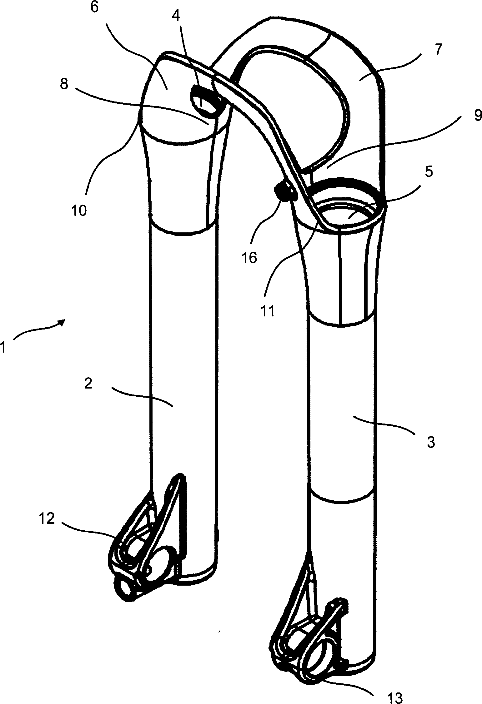
Die Erfindung betrifft ein Unterbein (1) für eine Federgabel mit zwei Tauchrohren (2, 3) mit jeweils einer Aufnahmeeinrichtung (4, 5) zur Aufnahme eines in der Aufnahmeeinrichtung verschiebbar gelagerten Standrohrs und mit zwei Stabilisatoren (6, 7), die den Ausfallenden der Tauchrohre gegenüberliegende Endbereiche der beiden Tauchrohre miteinander verbinden, wobei das Unterbein (1) eine Versteifungseinrichtung (8, 9) aufweist, die die beiden Stabilisatoren miteinander verbindet.The The invention relates to a lower leg (1) for a suspension fork with two dip tubes (2, 3), each with a receiving device (4, 5) for receiving a displaceable in the receiving device mounted standpipe and with two stabilizers (6, 7), the Dropouts of the dip tubes opposite end portions of the connecting two dip tubes, the lower leg (1) a stiffening device (8, 9) comprising the two stabilizers connects with each other.
Description
Die Erfindung betrifft ein Unterbein für eine Federgabel gemäß dem Oberbegriff von Anspruch 1 und eine Federgabel mit einem derartigen Unterbein.The The invention relates to a lower leg for a fork according to the The preamble of claim 1 and a suspension fork with such Lower leg.
Eine "Federgabel" bedeutet im Zusammenhang mit der vorliegenden Beschreibung und den vorliegenden Ansprüchen eine Fahrradgabel oder Motorradgabel, die zwei Tauchrohre aufweist, in die jeweils ein Standrohr federnd aufgenommen ist. Die Ausfallenden der Tauchrohre weisen eine Einrichtung zur Aufnahme der Achse eines Rades auf (normalerweise des Vorderrades, wobei aber bei unkonventionellen Rahmen auch eine Aufnahme des Hinterrades denkbar ist). Die Standrohre sind in den Tauchrohren verschiebbar gelagert, wobei eine Federung und Dämpfung vorgesehen ist, um beim Fahren auftretende Stöße abzufangen bzw. zu dämpfen. Je nach Fahrsituation kann die Federung bzw. Dämpfung verstellbar bzw. abschaltbar bzw. zuschaltbar sein.A "Fork" means in the context of the present description and the present claims a bicycle fork or motorcycle fork, the two dip tubes has, in each case a standpipe resilient is included. The dropouts of the dip tubes have a device for receiving the axle of a wheel (usually the front wheel, but with unconventional frame also a recording of the rear wheel is conceivable). The standpipes are slidable in the dip tubes stored, with a suspension and damping is provided to catch shocks when driving or to dampen. Depending on the driving situation, the suspension or Damping can be adjusted or switched off or switched on.
Ein "Unterbein" bedeutet im Zusammenhang mit der vorliegenden Beschreibung und den vorliegenden Ansprüchen die untere Baugruppe der Federgabel, die im Wesentlichen die beiden Tauchrohre umfasst. Die beiden Tauchrohre sind über einen oder mehrere Stabilisatoren verbunden, um eine gewisse Verwindungssteifigkeit des Unterbeins gegenüber der beim Fahren und insbesondere beim Einfedern, Kurvenfahren, Landen, bzw. Springen auftretenden Torsionskräfte und Biegekräfte zu erreichen. Die Stabilisatoren verbinden in der Regel die oberen Enden der Tauchrohre. An den anderen Enden der Tauchrohre sind jeweils Ausfallenden vorgesehen, welche jeweils eine Aufnahme für die Achse des Rads aufweisen.One "Lower leg" means in connection with the present description and the present claims, the lower assembly of Suspension fork, which essentially comprises the two dip tubes. The Both dip tubes are via one or more stabilizers connected to a certain torsional rigidity of the lower leg compared to when driving and in particular during compression, cornering, Landing, or jumping occurring torsional forces and bending forces to reach. The stabilizers usually connect the upper Ends of the dip tubes. At the other ends of the dip tubes are respectively Dropouts provided, each having a receptacle for have the axis of the wheel.
Ein
Unterbein für eine Federgabel gemäß dem
Oberbegriff von Anspruch 1 ist aus der
Es besteht bei dem bekannten Unterbein aber der Nachteil, dass an den Übergangsbereichen von den Stabilisatoren zu den Rohrfortsätzen Spannungsspitzen auftreten, die zu einer hohen Belastung führen. Daher müssen die Übergangsbereiche sehr stabil und somit schwer ausgebildet werden, um einem Spannungsbruch zu vermeiden. Bei extremen Fahrsituationen kann es überdies zu einer Beschädigung des Unterbeins kommen.It exists in the known lower leg but the disadvantage that at the transition areas of the stabilizers to the pipe extensions stress peaks occur, which lead to a high load. Therefore, must the transition areas very stable and thus difficult to train to avoid a voltage break. In extreme driving situations It may also damage the lower leg come.
Der Erfindung liegt daher die Aufgabe zugrunde, ein Unterbein für eine Federgabel gemäß dem Oberbegriff von Anspruch 1 anzugeben, bei dem trotz eines gewichtsarmen Aufbaus die beim Fahren auftretenden Spannungsspitzen im Vergleich zum Stand der Technik relativ klein sind.Of the Invention is therefore based on the object, a lower leg for a suspension fork according to the preamble of claim 1, in which, despite a low-weight construction when driving occurring voltage spikes in comparison to the prior art are relatively small.
Die Aufgabe der Erfindung wird mit einem Unterbein für eine Federgabel gemäß den Merkmalen von Anspruch 1 gelöst. Vorteilhafte Ausgestaltungen der Erfindung sind in den abhängigen Ansprüchen angegeben.The The object of the invention is with a lower leg for a Suspension fork according to the features of claim 1 solved. Advantageous embodiments of the invention are specified in the dependent claims.
Gemäß einer Ausführung der Erfindung wird ein Unterbein für eine Federgabel mit zwei Tauchrohren mit jeweils einer Aufnahmeeinrichtung zur Aufnahme eines in der Aufnahmeeinrichtung verschiebbar gelagerten Standrohrs und mit zwei Stabilisatoren angegeben, die den Ausfallenden der Tauchrohre gegenüberliegende Endbereiche der beiden Tauchrohre miteinander verbinden, wobei das Unterbein eine Versteifungseinrichtung aufweist, die die beiden Stabilisatoren miteinander verbindet.According to one Embodiment of the invention is a lower leg for a suspension fork with two dip tubes, each with a receiving device for receiving a displaceably mounted in the receiving device Standpipe and with two stabilizers that indicate the dropouts the dip tubes opposite end portions of the two Connect immersion tubes together, the lower leg a stiffening device has, which connects the two stabilizers together.
Bei Ausführungen, die mehr als zwei Stabilisatoren aufweisen, sollten erfindungsgemäß zumindest zwei der Stabilisatoren miteinander verbunden sein. Vorteilhafterweise sind bei mehr als zwei Stabilisatoren Versteifungseinrichtungen vorgesehen, die zumindest jeweils zwei Stabilisatoren miteinander verbinden und vorzugsweise gemäß den unten genannten vorteilhaften Weiterbildungen ausgebildet sind.at Versions that have more than two stabilizers, should according to the invention at least two of the stabilizers be connected to each other. Advantageously, more than two stabilizers provided stiffening means, at least each connect two stabilizers together and preferably according to the below-mentioned advantageous developments are formed.
Gemäß dem Stand der Technik sind die beiden Stabilisatoren nur über die Tauchrohre an ihren Enden starr miteinander verbunden. Durch die erfindungsgemäße Versteifungseinrichtung wird eine zusätzliche Festigkeit und/oder Steifigkeit erreicht. Die Versteifungseinrichtung kann dabei vorzugsweise auch mit den oberen Enden der beiden Tauchrohre verbunden sein. Alternativ kann die Versteifungseinrichtung nur mit den beiden Stabilisatoren verbunden sein. In diesem Fall ist es bevorzugt, dass die beiden Stabilisatoren nicht mit einer scharfen Kante, sondern mit einem Radius mit den beiden Tauchrohren verbunden sind. Der Radius sollte zumindest ungefähr 3 mm und vorzugsweise zumindest ungefähr 5 mm betragen.According to the State of the art, the two stabilizers are only about the dip tubes are rigidly connected at their ends. By the stiffening device according to the invention is achieved an additional strength and / or rigidity. The stiffening device may preferably also with the be connected to the upper ends of the two dip tubes. Alternatively, you can the stiffening device to be connected only to the two stabilizers. In this case it is preferable that the two stabilizers not with a sharp edge, but with a radius with the two dip tubes are connected. The radius should be at least about 3 mm and preferably at least about 5 mm.
Im Prinzip kann das erfindungsgemäße Unterbein der Federgabel auf einer oder beiden Seiten des darin anzuordnenden Rads auch mehr als ein Tauchrohr aufweisen, in das jeweils ein Standrohr der Federgabel verschiebbar aufgenommen wird. Ein derartiges Unterbein soll ebenfalls von dem Schutzumfang der Erfindung umfasst sein, wenn eine erfindungsgemäße Versteifungseinrichtung vorgesehen ist.In principle, the lower leg of the suspension fork according to the invention may also have more than one dip tube on one or both sides of the wheel to be arranged therein, in each of which a standpipe of the suspension fork is slidably received. One Such lower leg should also be included within the scope of the invention if a stiffener according to the invention is provided.
Erfindungsgemäß kann die Versteifungseinrichtung zumindest zwei Verbindungselemente aufweisen, die jeweils ein Ende des einen Stabilisators mit einem Ende des anderen Stabilisators verbinden und bezogen auf das Unterbein innerhalb der Aufnahmeinrichtungen für die Standrohre verlaufen.According to the invention the stiffening device have at least two connecting elements, each one end of the one stabilizer with one end of the connect to other stabilizer and related to the lower leg within the receiving devices for the stanchions run.
Erfindungsgemäß kann die Versteifungseinrichtung ein oder mehrere Verbindungselemente aufweisen, die die beiden Stabilisatoren oberhalb der Tauchrohre miteinander verbinden.According to the invention the stiffening device one or more fasteners have the two stabilizers above the dip tubes connect with each other.
Erfindungsgemäß können die Verbindungselemente der Versteifungseinrichtung Stege und/oder Drähte umfassen.According to the invention the connecting elements of the stiffening webs and / or wires include.
Die Stege und/oder Drähte können erfindungsgemäß auch in Form eines Gitters und/oder Fachwerks angeordnet sein, wobei die Anordnung vorzugsweise derart ist, dass die beim Fahren auftretenden Spannungen möglichst entlang der Stege und/oder Drähte verlaufen. Bei den Ausführungen mit Stegen, können die zwischen den Stegen bestehenden Lücken freigelassen und/oder durch dünne Flächen aufgefüllt werden. Die dünnen Flächen sind dabei vorzugsweise derart angeordnet, dass die Flächen außen angeordnet sind. Aus optischen oder anderen Gründen können sie jedoch auch innen oder in der Mitte angeordnet sein.The Webs and / or wires according to the invention also be arranged in the form of a grid and / or truss, wherein the arrangement is preferably such that the occurring during driving Strains possibly along the webs and / or wires run. In the versions with bars, can the gaps between the webs are released and / or filled by thin areas become. The thin surfaces are preferably arranged such that the surfaces arranged outside are. For optical or other reasons may However, they can also be arranged inside or in the middle.
Erfindungsgemäß können die Verbindungselemente der Versteifungseinrichtung Stege umfassen, die mit den beiden Stabilisatoren und jeweils einem Tauchrohr verbunden sind.According to the invention comprise the connecting elements of the stiffening webs, connected to the two stabilizers and one dip tube each are.
Diese Ausführungen haben den Vorteil, dass das Verbindungselement besonders leicht bauend ausgeführt werden kann. Vorzugsweise kann dabei das Verbindungselement entlang seines gesamten Verlaufs mit dem oberen Ende eines Tauchrohres verbunden sein.These Designs have the advantage that the connecting element particularly easy to build can be performed. Preferably can thereby the connecting element along its entire course be connected to the upper end of a dip tube.
Erfindungsgemäß können die Verbindungselemente der Versteifungseinrichtung Stege umfassen, die eine kleinste Höhe von zumindest ungefähr 0,5 mm, vorzugsweise von zumindest mindestens ungefähr 1 mm, weiter vorzugsweise von zumindest ungefähr 2 mm, weiter vorzugsweise von zumindest ungefähr 3 mm, weiter vorzugsweise von zumindest ungefähr 5 mm und bevorzugt von ungefähr zumindest ungefähr 10 mm aufweisen.According to the invention comprise the connecting elements of the stiffening webs, the smallest height of at least about 0.5 mm, preferably at least at least about 1 mm, more preferably at least about 2 mm, further preferably at least about 3 mm, more preferably of at least about 5 mm, and preferably about at least about 10 mm.
Erfindungsgemäß können die Verbindungselemente der Versteifungseinrichtung Stege umfassen, die eine kleinste Höhe von weniger als ungefähr 50 mm, vorzugsweise von weniger als ungefähr 40 mm, weiter vorzugsweise von weniger als ungefähr 30 mm, weiter vorzugsweise von weniger als ungefähr 20 mm und bevorzugt von ungefähr weniger als ungefähr 15 mm aufweisen.According to the invention comprise the connecting elements of the stiffening webs, the smallest height less than about 50 mm, preferably less than about 40 mm, further preferably less than about 30 mm, more preferably less than about 20 mm, and preferably about less than about 15 mm.
Erfindungsgemäß können die Verbindungselemente der Versteifungseinrichtung Stege umfassen, die dünnere und dickere Bereiche umfassen, wobei die dickeren Bereiche vorzugsweise in Bereichen der Stege vorgesehen sind, in denen beim Fahren größere Spannungen bzw. Belastungen auftreten und die dünneren Bereiche vorzugsweise in Bereichen der Stege vorgesehen sind, in denen beim Fahren kleinere Spannungen bzw. Belastungen auftreten.According to the invention comprise the connecting elements of the stiffening webs, the thinner and thicker areas include, with the thicker ones Areas are preferably provided in areas of the webs, in those when driving greater voltages or loads occur and the thinner areas preferably in areas the webs are provided, in which when driving smaller voltages or loads occur.
Erfindungsgemäß kann die Breite bzw. Stärke der Verbindungselemente der Versteifungseinrichtung und/oder die Breite bzw. Stärke der dickeren Bereiche der Verbindungselemente der Versteifungseinrichtung zumindest ungefähr 0,5 mm, vorzugsweise zumindest mindestens ungefähr 1 mm, weiter vorzugsweise zumindest ungefähr 2 mm, und bevorzugt ungefähr 3 mm betragen.According to the invention the width or strength of the connecting elements of the stiffening device and / or the width or thickness of the thicker regions of the Connecting elements of the stiffening device at least approximately 0.5 mm, preferably at least at least about 1 mm, more preferably at least about 2 mm, and preferably about 3 mm.
Erfindungsgemäß kann die Breite bzw. Stärke der Verbindungselemente der Versteifungseinrichtung und/oder die Breite bzw. Stärke der dickeren Bereiche der Verbindungselemente der Versteifungseinrichtung weniger als ungefähr 10 mm, vorzugsweise von weniger als ungefähr 8 mm, weiter vorzugsweise weniger als ungefähr 6 mm, weiter vorzugsweise weniger als ungefähr 5 mm, weiter vorzugsweise weniger als ungefähr 4 mm, und bevorzugt ungefähr 3 mm betragen.According to the invention the width or strength of the connecting elements of the stiffening device and / or the width or thickness of the thicker regions of the Fasteners of the stiffener less than about 10 mm, preferably less than about 8 mm, on preferably less than about 6 mm, more preferably less than about 5 mm, more preferably less as about 4 mm, and preferably about 3 mm be.
Erfindungsgemäß können die Verbindungselemente der Versteifungseinrichtung Stege umfassen, die Aussparungen, Durchbrüche und/oder dünne flächige Bereiche sowie Rippen und/oder Streben umfassen, wobei die Rippen und/oder Streben vorzugsweise in Bereichen der Stege vorgesehen sind, in denen beim Fahren größere Spannungen bzw. Belastungen auftreten und die Aussparungen, Durchbrüche und/oder dünnen flächigen Bereiche vorzugsweise in Bereichen der Stege vorgesehen sind, in denen beim Fahren kleinere Spannungen bzw. Belastungen auftreten.According to the invention comprise the connecting elements of the stiffening webs, the recesses, breakthroughs and / or thin areal Ranges and ribs and / or struts include, with the ribs and / or struts are preferably provided in areas of the webs are where in driving greater tensions or loads occur and the recesses, breakthroughs and / or thin area areas preferably are provided in areas of the webs, in which smaller when driving Strains or loads occur.
Erfindungsgemäß können die Verbindungselemente der Versteifungseinrichtung Rippen umfassen, die vorzugsweise entlang der Ränder der Verbindungselemente verlaufen.According to the invention the connecting elements of the stiffening device comprise ribs, preferably along the edges of the connecting elements run.
Erfindungsgemäß kann das Unterbein aus einem Druckgussmaterial und/oder einem Kunststoffmaterial ausgebildet sein, wobei das Druckgussmaterial vorzugsweise Aluminiumdruckguss- und/oder Magnesiumdruckgussmaterial umfasst, und wobei das Kunststoffmaterial faserverstärkten Kunststoff und/oder Carbon umfasst. Dabei können die Fasern des faserverstärkten Kunststoffes vorzugsweise Kohlefasern, Glasfasern und/oder Kunststofffasern umfassen. Weiter vorzugsweise kann die Richtung der Fasern im Wesentlichen unidirektional sein, wobei die Fasern vorzugsweise entlang der wirkenden Spannungen bzw. Kräfte ausgerichtet sind. Die bevorzugte Ausrichtung der Fasern hat den Vorteil, dass die auftretenden Spannungen bzw. Kräfte besser aufgenommen und unter Bildung möglichst geringer Verwindungen weitergeleitet werden können.According to the invention, the lower leg may be formed from a diecasting material and / or a plastic material, wherein the diecasting material preferably comprises die-cast aluminum and / or magnesium die casting material, and wherein the plastic material comprises fiber reinforced plastic and / or carbon. The fibers of the fiber-reinforced plastic may preferably comprise carbon fibers, glass fibers and / or synthetic fibers. More preferably, the direction of the fibers may be substantially unidirectional, wherein the fibers are preferably aligned along the acting stresses or forces. The preferred orientation of the fibers has the advantage that the occurring stresses or forces can be better absorbed and forwarded to form the least possible twisting.
Erfindungsgemäß kann die Versteifungseinrichtung die beiden Stabilisatoren im Wesentlichen in der Mitte zwischen den beiden Tauchrohren miteinander verbinden. Die Stabilisatoren sind in der Regel und vorzugsweise mittig zu den beiden Tauchrohren angeordnet. Daher kann man gemäß dieser Ausführung der Erfindung mit anderen Worten auch sagen, dass das Verbindungselement der Versteifungseinrichtung die Mitten der beiden Stabilisatoren miteinander verbindet. Vorzugsweise kann das durch einen Steg geschehen, der gemäß einer Ausführung der Erfindung auch etwas bogenförmig ausgebildet sein kann, um der einfedernden Gabelbrücke Platz zum Einfedern zu bieten. Alternativ kann die Versteifungseinrichtung auch als Draht ausgebildet sein. In diesem Fall wirkt die Versteifungseinrichtung nur betreffend von Zugkräften, d. h. Kräften, die die beiden Stabilisatoren voneinander entfernen würden.According to the invention the stiffening device the two stabilizers substantially connect in the middle between the two dip tubes. The stabilizers are usually and preferably centrally too arranged the two dip tubes. Therefore, you can according to this Embodiment of the invention in other words also say that the connecting element of the stiffening means the centers of connects two stabilizers together. Preferably, the done by a bridge, which according to one embodiment the invention may also be slightly curved, There is room for springing around the spring-loaded fork bridge Offer. Alternatively, the stiffening device can also be used as a wire be educated. In this case, the stiffening device acts only concerning tensile forces, d. H. forces which would remove the two stabilizers from each other.
Erfindungsgemäß kann die Versteifungseinrichtung die beiden Stabilisatoren im Wesentlichen an den seitlichen Enden der Stabilisatoren miteinander verbinden.According to the invention the stiffening device, the two stabilizers substantially connect the lateral ends of the stabilizers together.
Erfindungsgemäß können die Stabilisatoren Verbindungsbrücken umfassen, die die Tauchrohre im Wesentlichen jeweils vor bzw. hinter den Aufnahmeeinrichtungen miteinander verbinden.According to the invention the stabilizers comprise connecting bridges, which the Diving tubes substantially in front of or behind the receiving devices connect with each other.
Erfindungsgemäß kann das Unterbein zumindest eine Aufnahmeeinrichtung zur Aufnahme einer Betätigungsleitung für einen Verstellmechanismus bzw. eine Bremsvorrichtung aufweisen. Der Verstellmechanismus kann beispielsweise die Feder- bzw. Dämpfungscharakteristik der Federgabel beeinflussen. Der Eingang kann beispielsweise an dem Ausfallende eines oder beider Tauchrohre vorgesehen sein. In diesem Fall ist es vorteilhaft, die Aufnahmeeinrichtung für die Betätigungsleitung (beispielsweise einen Seilzug und/oder eine Druckleitung (Hydraulik oder Gas)) an dem Unterbein vorzusehen, weil ein fester Abstand von der Aufnahme bis zum Eingang besteht.According to the invention the lower leg at least one receiving device for receiving a Actuation line for an adjustment mechanism or have a braking device. The adjustment mechanism can for example, the spring or damping characteristic affect the suspension fork. For example, the input can be on be provided the dropout of one or both dip tubes. In In this case, it is advantageous, the receiving device for the actuating line (for example, a cable and / or to provide a pressure line (hydraulic or gas)) on the lower leg, because there is a fixed distance from the recording to the entrance.
Die Bremsvorrichtung kann dabei beispielsweise eine an einem Ausfallende eines Tauchrohres angeordnete Bremszange einer Scheibenbremse umfassen. Der Anbau an dem Unterbein hat den Vorteil, dass der Abstand zwischen Aufnahmeeinrichtung und Bremseinrichtung fest ist und somit keine Leitungsreserve für die Betätigungsleitung vorgesehen werden muss. Erfindungsgemäß kann dabei die Aufnahmeinrichtung vorzugsweise an der Versteifungseinrichtung angeordnet sein. Die Aufnahmevorrichtung ist gemäß dieser Ausführung der Erfindung somit oberhalb der beiden Tauchrohre, so dass die Betätigungsleitung versteckt verlegt werden kann. Alternativ oder zusätzlich kann dabei die Aufnahmeinrichtung an einem der Tauchrohre angeordnet sein. Selbstverständlich können auch mehrere Aufnahmevorrichtungen vorgesehen sein.The Braking device can, for example, one at a dropout a caliper arranged brake caliper a disc brake include. The attachment to the lower leg has the advantage that the distance between Receiving device and braking device is fixed and thus no line reserve must be provided for the control line. According to the invention, the receiving device preferably be arranged on the stiffening device. The Receiving device is according to this embodiment The invention thus above the two dip tubes, so that the actuating line Hidden can be laid. Alternatively or in addition can thereby arranged the receiving device on one of the dip tubes be. Of course, several recording devices be provided.
Die Erfindung wird im Folgenden anhand der in den Figuren gezeigten Ausführungsbeispiele näher beschrieben.The Invention will be described below with reference to the figures shown in FIGS Embodiments described in more detail.
Bei
den weiteren Ausführungsbeispielen bzw. Varianten werden
für entsprechende Merkmale und Elemente, soweit nicht explizit
aufgeführt, die gleichen aber um jeweils
Die
Das
Unterbein
An
ihrem oberen Ende haben die Tauchrohre
Die
beiden Tauchrohre
Die
beiden Stabilisatoren
An
den außen liegenden Ansatzpunkten der Stabilisatoren
An
dem vorderen Stabilisator
Die
Bei
der alternativen Ausführung gemäß
Bei
der alternativen Ausführung gemäß
Bei
der alternativen Ausführung gemäß
Bei
der alternativen Ausführung gemäß
Bei
der alternativen Ausführung gemäß
Bei
der alternativen Ausführung gemäß
Die
jeweils andere in den
Alle Ausführungen der Erfindung weisen vorzugsweise eine zur Radmittelebene symmetrisch ausgebildete Versteifungseinrichtung auf.All Embodiments of the invention preferably have a Radmittelebene symmetrically formed stiffening device on.
Alternative Ausführungen sind denkbar, insbesondere Kombination und/oder weitere Alternativen der in den Ausführungsbeispielen dargestellten und beschriebenen Ausführungen der Erfindung.alternative Designs are conceivable, in particular combination and / or Other alternatives of the illustrated in the embodiments and described embodiments of the invention.
In der Beschreibung des Ausführungsbeispiels werden folgende Bezugszeichen verwendet:In The description of the embodiment will be as follows Reference number used:
- 11
- Unterbeinlower leg
- 22
- Tauchrohrdip tube
- 33
- Tauchrohrdip tube
- 44
- Aufnahmeeinrichtung für Standrohrrecording device for standpipe
- 55
- Aufnahmeeinrichtung für Standrohrrecording device for standpipe
- 66
- vorderer Stabilisatorfront stabilizer
- 77
- hinterer Stabilisatorrear stabilizer
- 88th
- Versteifungsgliedstiffener
- 99
- Versteifungsgliedstiffener
- 1010
- Verstärkungsgliedreinforcing member
- 1111
- Verstärkungsgliedreinforcing member
- 1212
-
Achsaufnahme
(am Ausfallende des Tauchrohrs
2 )Axle holder (at the dropout of the dip tube2 ) - 1313
-
Achsaufnahme
(am Ausfallende des Tauchrohrs
3 )Axle holder (at the dropout of the dip tube3 ) - 1414
- BremszangenaufnahmeBrake caliper adapter
- 1515
- BremszangenaufnahmeBrake caliper adapter
- 1616
- Aufnahme für Verstelleinrichtungadmission for adjusting device
- 1717
- Steckachsefloating axle
- 1818
- Standrohrstandpipe
- 1919
- Standrohrstandpipe
- 2020
- Gabelbrückecrown
- 2121
- Schaftrohr (wird im Steuerrohr des Fahrradrahmens aufgenommen)steerer (will be included in the head tube of the bicycle frame)
- 20912091
- Aussparungrecess
- 20922092
- Aussparungrecess
- 30913091
- Verbindungsdrahtconnecting wire
- 40914091
- Verbindungsdrahtconnecting wire
- 40924092
- Verbindungsdrahtconnecting wire
- 40934,093
- Versteifungsdrahtstiffening wire
- 50915091
- Verbindungsbrückeconnecting bridge
- 60916091
- Verbindungsbrückeconnecting bridge
- 60926092
- Mittelstegcenter web
- 60936093
- Aussparungrecess
- 60946094
- Aussparungrecess
- 70917091
- Verbindungsbrückeconnecting bridge
ZITATE ENTHALTEN IN DER BESCHREIBUNGQUOTES INCLUDE IN THE DESCRIPTION
Diese Liste der vom Anmelder aufgeführten Dokumente wurde automatisiert erzeugt und ist ausschließlich zur besseren Information des Lesers aufgenommen. Die Liste ist nicht Bestandteil der deutschen Patent- bzw. Gebrauchsmusteranmeldung. Das DPMA übernimmt keinerlei Haftung für etwaige Fehler oder Auslassungen.This list The documents listed by the applicant have been automated generated and is solely for better information recorded by the reader. The list is not part of the German Patent or utility model application. The DPMA takes over no liability for any errors or omissions.
Zitierte PatentliteraturCited patent literature
- - DE 19531844 A1 [0004] DE 19531844 A1 [0004]
Claims (22)
Priority Applications (9)
| Application Number | Priority Date | Filing Date | Title |
|---|---|---|---|
| DE102007040887A DE102007040887A1 (en) | 2007-08-29 | 2007-08-29 | Lower leg for a suspension fork |
| TW097130732A TWI483868B (en) | 2007-08-29 | 2008-08-12 | Lower leg for a suspension fork |
| EP08785721A EP2188170B1 (en) | 2007-08-29 | 2008-08-27 | Lower leg for a suspension fork |
| CN200880110191.XA CN101878150A (en) | 2007-08-29 | 2008-08-27 | Lower support for suspension fork |
| AT08785721T ATE519665T1 (en) | 2007-08-29 | 2008-08-27 | LOWER LEG FOR A SUSPENSION FORK |
| DE112008002327T DE112008002327A5 (en) | 2007-08-29 | 2008-08-27 | Lower leg for a suspension fork |
| PCT/EP2008/007020 WO2009030412A1 (en) | 2007-08-29 | 2008-08-27 | Lower leg for a suspension fork |
| US12/714,650 US8439381B2 (en) | 2007-08-29 | 2010-03-01 | Lower leg for a suspension fork |
| US13/845,296 US8678415B2 (en) | 2007-08-29 | 2013-03-18 | Lower leg for a suspension fork |
Applications Claiming Priority (1)
| Application Number | Priority Date | Filing Date | Title |
|---|---|---|---|
| DE102007040887A DE102007040887A1 (en) | 2007-08-29 | 2007-08-29 | Lower leg for a suspension fork |
Publications (1)
| Publication Number | Publication Date |
|---|---|
| DE102007040887A1 true DE102007040887A1 (en) | 2009-03-05 |
Family
ID=40116411
Family Applications (2)
| Application Number | Title | Priority Date | Filing Date |
|---|---|---|---|
| DE102007040887A Ceased DE102007040887A1 (en) | 2007-08-29 | 2007-08-29 | Lower leg for a suspension fork |
| DE112008002327T Withdrawn DE112008002327A5 (en) | 2007-08-29 | 2008-08-27 | Lower leg for a suspension fork |
Family Applications After (1)
| Application Number | Title | Priority Date | Filing Date |
|---|---|---|---|
| DE112008002327T Withdrawn DE112008002327A5 (en) | 2007-08-29 | 2008-08-27 | Lower leg for a suspension fork |
Country Status (7)
| Country | Link |
|---|---|
| US (2) | US8439381B2 (en) |
| EP (1) | EP2188170B1 (en) |
| CN (1) | CN101878150A (en) |
| AT (1) | ATE519665T1 (en) |
| DE (2) | DE102007040887A1 (en) |
| TW (1) | TWI483868B (en) |
| WO (1) | WO2009030412A1 (en) |
Families Citing this family (4)
| Publication number | Priority date | Publication date | Assignee | Title |
|---|---|---|---|---|
| DE102008053700A1 (en) * | 2008-10-29 | 2010-05-06 | Dt Swiss Ag | Diving tube unit for a suspension fork |
| CN102241263B (en) * | 2010-05-12 | 2013-04-24 | 捷安特(中国)有限公司 | Front fork outer pipe for bicycle |
| US20240227978A9 (en) * | 2022-10-19 | 2024-07-11 | Fox Factory, Inc. | Fork arch |
| TWI898290B (en) * | 2023-10-18 | 2025-09-21 | 美商福克斯制造有限公司 | Fork arch |
Citations (7)
| Publication number | Priority date | Publication date | Assignee | Title |
|---|---|---|---|---|
| DE899444C (en) * | 1951-12-29 | 1953-12-10 | Kreidler Dipl Ing Alfred | Telescopic front wheel fork with sliding tubes connected by a bridge to form a sliding bracket and a method for producing this sliding bracket |
| DE2746879A1 (en) * | 1977-10-19 | 1979-04-26 | Lothar Schneier | Motorcycle front fork with dampers - has bridging stiffener between telescopic tubes holding wheel spindle to equalise deflection |
| CH612889A5 (en) * | 1976-10-04 | 1979-08-31 | Fritz W Egli | Telescopic front-wheel fork for motorcycles |
| DE7932413U1 (en) * | 1979-11-16 | 1980-02-14 | Rost, Hans-Joachim, 4406 Drensteinfurt | STABILIZER FOR THE FRONT WHEEL FORK OF A MOTORCYCLE |
| DE3437052A1 (en) * | 1984-10-09 | 1986-04-17 | Bayerische Motoren Werke AG, 8000 München | Fork stabiliser |
| DE19531844A1 (en) | 1995-08-29 | 1997-03-06 | Fichtel & Sachs Ag | Shock absorber for bicycles |
| DE20212876U1 (en) * | 2002-08-22 | 2002-11-14 | Lin, Jack, Alisio Viejo, Ca. | Front wheel cushioning for bicycles |
Family Cites Families (11)
| Publication number | Priority date | Publication date | Assignee | Title |
|---|---|---|---|---|
| US5078417A (en) * | 1989-07-19 | 1992-01-07 | Cycle Composites, Inc. | All terrain cycle fork with fiber reinforced resin blades and crown and method of making same |
| US5653007A (en) * | 1995-04-17 | 1997-08-05 | Answer Products, Inc. | Method for producing a bicycle fork brake arch and legs assembly |
| US5562297A (en) * | 1995-12-12 | 1996-10-08 | Lin; Chun-San | Engagement between a connecting element and a front fork |
| DE29615349U1 (en) * | 1996-09-05 | 1996-11-28 | Kramer-Massow, Klaus, 79294 Sölden | Telescopic two-wheel suspension with a large overlap area of the tubes sliding into each other |
| US6260870B1 (en) * | 2000-02-08 | 2001-07-17 | Jeeng-Neng Fan | Structure telescopic-type front fork cushion for bicycles |
| US6439077B2 (en) * | 2000-04-06 | 2002-08-27 | Avid Llc | Cable feed for a cable actuated bicycle component |
| TW562010U (en) | 2002-06-06 | 2003-11-11 | Jack Lin | Front suspension device for bicycles |
| US6592108B1 (en) * | 2002-07-18 | 2003-07-15 | Marc Schmidt-Thieme | Suspension device |
| TWM262438U (en) * | 2004-08-20 | 2005-04-21 | Hsin Lung Accessories Co Ltd | Locking structure of shock absorber |
| TWM272732U (en) * | 2005-03-22 | 2005-08-11 | Chin-Sung Tsai | Guiding wire tube for front fork of bike |
| US7621549B2 (en) * | 2006-07-26 | 2009-11-24 | Trek Bicycle Corporation | Bicycle light system |
-
2007
- 2007-08-29 DE DE102007040887A patent/DE102007040887A1/en not_active Ceased
-
2008
- 2008-08-12 TW TW097130732A patent/TWI483868B/en not_active IP Right Cessation
- 2008-08-27 EP EP08785721A patent/EP2188170B1/en not_active Not-in-force
- 2008-08-27 DE DE112008002327T patent/DE112008002327A5/en not_active Withdrawn
- 2008-08-27 AT AT08785721T patent/ATE519665T1/en active
- 2008-08-27 CN CN200880110191.XA patent/CN101878150A/en active Pending
- 2008-08-27 WO PCT/EP2008/007020 patent/WO2009030412A1/en not_active Ceased
-
2010
- 2010-03-01 US US12/714,650 patent/US8439381B2/en not_active Expired - Fee Related
-
2013
- 2013-03-18 US US13/845,296 patent/US8678415B2/en not_active Expired - Fee Related
Patent Citations (7)
| Publication number | Priority date | Publication date | Assignee | Title |
|---|---|---|---|---|
| DE899444C (en) * | 1951-12-29 | 1953-12-10 | Kreidler Dipl Ing Alfred | Telescopic front wheel fork with sliding tubes connected by a bridge to form a sliding bracket and a method for producing this sliding bracket |
| CH612889A5 (en) * | 1976-10-04 | 1979-08-31 | Fritz W Egli | Telescopic front-wheel fork for motorcycles |
| DE2746879A1 (en) * | 1977-10-19 | 1979-04-26 | Lothar Schneier | Motorcycle front fork with dampers - has bridging stiffener between telescopic tubes holding wheel spindle to equalise deflection |
| DE7932413U1 (en) * | 1979-11-16 | 1980-02-14 | Rost, Hans-Joachim, 4406 Drensteinfurt | STABILIZER FOR THE FRONT WHEEL FORK OF A MOTORCYCLE |
| DE3437052A1 (en) * | 1984-10-09 | 1986-04-17 | Bayerische Motoren Werke AG, 8000 München | Fork stabiliser |
| DE19531844A1 (en) | 1995-08-29 | 1997-03-06 | Fichtel & Sachs Ag | Shock absorber for bicycles |
| DE20212876U1 (en) * | 2002-08-22 | 2002-11-14 | Lin, Jack, Alisio Viejo, Ca. | Front wheel cushioning for bicycles |
Also Published As
| Publication number | Publication date |
|---|---|
| US8678415B2 (en) | 2014-03-25 |
| EP2188170A1 (en) | 2010-05-26 |
| ATE519665T1 (en) | 2011-08-15 |
| US8439381B2 (en) | 2013-05-14 |
| DE112008002327A5 (en) | 2011-04-28 |
| TW200927586A (en) | 2009-07-01 |
| CN101878150A (en) | 2010-11-03 |
| TWI483868B (en) | 2015-05-11 |
| US20130241171A1 (en) | 2013-09-19 |
| WO2009030412A1 (en) | 2009-03-12 |
| US20100164200A1 (en) | 2010-07-01 |
| EP2188170B1 (en) | 2011-08-10 |
Similar Documents
| Publication | Publication Date | Title |
|---|---|---|
| DE102011119246B4 (en) | Lightweight construction element for a body | |
| DE102011016015B4 (en) | Lattice boom crane and lattice boom | |
| WO2013029846A1 (en) | Holder for a spring | |
| DE102015007636A1 (en) | Lattice piece for a lattice boom, lattice boom and crane | |
| DE102017120764B4 (en) | crane | |
| EP2188170B1 (en) | Lower leg for a suspension fork | |
| DE102007002609B3 (en) | Motor vehicle has stiffening struts, at least one with two sheet elements, and at least one tension belt joining them, whereby opposing sheet elements of a strut are arranged in opposite directions in a plane | |
| DE102014106174A1 (en) | The bicycle frame | |
| AT514406A1 (en) | bicycle | |
| EP2062803A1 (en) | Motor vehicle | |
| EP3293841B1 (en) | Pivoting anchor for securing conductors | |
| DE102018114245A1 (en) | Schienenfahrzeugbugnase | |
| DE102021102050A1 (en) | Battery case, motor vehicle and method for providing a battery case | |
| DE102013215228B3 (en) | Aircraft fuselage structure | |
| DE102009016935A1 (en) | Crossbeam for vehicle, particularly construction site vehicle, comprises two guide stands for connecting crossbeam to corresponding longitudinal supports of vehicle | |
| DE102008020811A1 (en) | Rigid bicycle fork e.g. suspension fork, has two fork blades connected with fork shaft, and fastening units for fastening traction mechanism that causes elastic deformation of partially elastically deformable lever of blades | |
| EP4173938A1 (en) | Synthetic bicycle handlebars | |
| DE102016203173A1 (en) | Reinforcement frame for a motor vehicle and hereby equipped motor vehicle | |
| DE102014218450A1 (en) | Vehicle head for attachment to the front side of a track-bound vehicle, in particular a rail vehicle | |
| DE102013020229A1 (en) | Support frame for motor vehicle e.g. truck, has holding unit with connecting element that is arranged extending between two longitudinal frame elements and is connected to two longitudinal frame elements | |
| DE102013112665A1 (en) | Bicycle handlebar system | |
| DE102013217217B4 (en) | Swivel bearing (III) | |
| DE102005045446B4 (en) | Chassis support of a chassis, especially for a crane | |
| DE102011052270A1 (en) | Bicycle frame has supporting frame part made from extruded profiled, where extruded profile has multiple chambers, and frame part has openings of extruded chambers on its top side and on its bottom side | |
| DE102015000323B4 (en) | Vehicle body with load-reducing tension element in partially covered frontal collisions |
Legal Events
| Date | Code | Title | Description |
|---|---|---|---|
| OP8 | Request for examination as to paragraph 44 patent law | ||
| 8131 | Rejection |