HINTERGRUND DER ERFINDUNGBACKGROUND OF THE INVENTION
Die vorliegende Erfindung bezieht sich auf eine Elektrobremse zum Erzeugen einer Bremskraft entsprechend einem Drehmoment eines Motors. Genauer gesagt bezieht sich die vorliegende Erfindung auf eine Elektrobremse, die mit einer Parkbremsfunktion ausgestattet ist.The present invention relates to an electric brake for generating a braking force corresponding to a torque of an engine. More specifically, the present invention relates to an electric brake equipped with a parking brake function.
Als ein Beispiel einer elektrischen Bremse ist eine elektrische Bremse zu nennen, umfassend einen Sattel mit einem darin vorgesehenen Kolben, einem Elektromotor und einen Dreh-Linearbewegungs-Wandelmechanismus zum Ermöglichen, dass die Rotation des Motors in eine Linearbewegung umgewandelt und auf den Kolben übertragen wird. Auf den Kolben wird entsprechend der Rotation eines Rotors des Motors ein Schub aufgebracht, um hierdurch einen Bremsbelag gegen einen Scheibenrotor zu drücken, wodurch eine Bremskraft erzeugt wird. Normalerweise wird in dieser Elektrobremse eine auf ein Bremspedal aufgebrachte Fahrerkraft oder ein Hub des Bremspedals durch einen Sensor erfasst, und die Rotation (der Rotationswinkel) des Motors wird basierend auf einen durch den Sensor erfassten Wert gesteuert, um hierdurch eine gewünschte Bremskraft zu erzielen.As an example of an electric brake, there may be mentioned an electric brake comprising a caliper having a piston therein, an electric motor, and a rotary-linear motion conversion mechanism for allowing the rotation of the motor to be converted to linear motion and transmitted to the piston. On the piston, a thrust is applied in accordance with the rotation of a rotor of the motor to thereby press a brake pad against a disc rotor, whereby a braking force is generated. Normally, in this electric brake, a brake force applied to a brake pedal or a stroke of the brake pedal is detected by a sensor, and the rotation (rotation angle) of the engine is controlled based on a value detected by the sensor to thereby obtain a desired braking force.
Kürzlich wurden verschiedene Versuche vorgenommen, um die Vorteile einer solchen Elektrobremse durch darin Vorsehen eines Parkbremsmechanismus (PKB) zu erhöhen.Recently, various attempts have been made to increase the advantages of such an electric brake by providing a parking brake mechanism (PKB).
Beispielsweise gibt es eine Elektrobremse mit einem Parkbremsmechanismus, bei welcher wenn eine Aktorspule des Parkbremsmechanismus von der Energie getrennt wird, ein Aktorkolben unter der Kraft einer Druckfeder zurückgezogen wird, so dass ein Schwenkarm mit einer Eingriffsklaue in einer aufrechten Ausgangsposition ist und in einen Zahnabschnitt einer Sperrklinke eingreift, um hierdurch die Parkbremse in einen aktiven Zustand zu setzen. Wenn die Aktorspule mit Energie beaufschlagt wird, wird der Aktorkolben vorgeschoben (Ausfahrhub), um hierdurch ein Lösen der Eingriffsklaue des Schwenkarms von dem Zahnabschnitt der Sperrklinke auszuführen und somit die Parkbremse zu lösen (siehe 6 bis 8 der JP 2003-42199 A ).For example, there is an electric brake with a parking brake mechanism in which, when an actuator coil of the parking brake mechanism is disconnected from the energy, an actuator piston is retracted under the force of a compression spring, so that a pivot arm with an engagement claw in an upright starting position and a tooth portion of a pawl engages to thereby set the parking brake in an active state. When the actuator coil is energized, the actuator piston is advanced (extension stroke) to thereby perform disengagement of the engagement claw of the swing arm from the teeth portion of the pawl and thus release the parking brake (see 6 to 8th of the JP 2003-42199 A ).
Ferner ist ein weiteres Beispiel einer Elektrobremse mit einem Parkbremsmechanismus offenbart. Bei diesem Beispiel wird zum Aufbringen der Parkbremse ein Aktorkolben durch Energiebeaufschlagen einer Aktorspule vorgeschoben (Ausfahrhub), um hierdurch eine Eingriffsklaue mit einem Zahnabschnitt einer Sperrklinke entgegen einer Kraft einer Zugfeder in Eingriff zu bringen. Um die Parkbremse zu lösen, wird der Elektromotor in einer Richtung zum Bremsen betrieben, während die Aktorspule von der Energie getrennt ist, um hierdurch den Eingriff zwischen der Eingriffsklaue und dem Zahnabschnitt der Sperrklinke zu lösen. Als Ergebnis hieraus wird die Eingriffsklaue durch die Zugfeder gezogen und von dem Zahnabschnitt der Sperrklinke gelöst, wodurch die Parkbremse gelöst wird (siehe 9 und 10 der JP 2003-42199 A ).Further, another example of an electric brake with a parking brake mechanism is disclosed. In this example, to apply the parking brake, an actuator piston is advanced by energizing an actuator coil (extension stroke), thereby engaging an engagement claw with a teeth portion of a pawl against a force of a tension spring. In order to release the parking brake, the electric motor is operated in a direction for braking while the actuator coil is disconnected from the power, thereby releasing the engagement between the engagement claw and the teeth portion of the pawl. As a result, the engagement claw is pulled by the tension spring and released from the tooth portion of the pawl, whereby the parking brake is released (see 9 and 10 of the JP 2003-42199 A ).
Falls bei diesen bekannten Techniken der Aktor oder der Elektromotor eine Fehlfunktion aufweist, oder die Stromzufuhr zu der Spule infolge einer Fehlfunktion eines Bauteils zum Zuführen eines Stroms zu dem Aktor oder dem Motor unmöglich wird, wenn der Parkbremsmechanismus betrieben wird (wenn die Parkbremse aufgebracht wird), wird die Eingriffsklaue kontinuierlich an der Sperrklinke gehalten. In diesem Falle kann die Parkbremse nicht gelöst werden, falls keine Gegenmaßnahme getroffen wird, und das Fahrzeug kann nicht bewegt werden, selbst nicht als zeitweise Maßnahme. Daher ist es wünschenswert, das oben genannte Problem der bekannten Techniken zu lösen.In these known techniques, if the actuator or the electric motor malfunctions or the power supply to the coil becomes impossible due to a malfunction of a component for supplying a current to the actuator or the motor when the parking brake mechanism is operated (when the parking brake is applied) , the engagement claw is continuously held on the pawl. In this case, the parking brake can not be released if no countermeasure is taken, and the vehicle can not be moved, even as a temporary measure. Therefore, it is desirable to solve the above problem of the known techniques.
Die EP 1 460 301 A2 betrifft eine elektromechanisch betätigbare Scheibenbremse mit einer Betätigungseinheit, die im Wesentlichen durch einen Elektromotor gebildet ist, dessen Rotor durch eine Verriegelungseinheit verriegelbar ist, so dass eine integrierte Feststellbremsvorrichtung vorgesehen ist. Ferner ist hierfür eine mechanische Notlösevorrichtung vorgesehen. Ähnliche Anordnungen gehen aus der JP 2001-234958 A und der EP 0 916 866 A2 hervor.The EP 1 460 301 A2 relates to an electromechanically actuated disc brake with an actuating unit, which is essentially formed by an electric motor whose rotor is lockable by a locking unit, so that an integrated parking brake device is provided. Furthermore, a mechanical emergency release device is provided for this purpose. Similar orders go out of the box JP 2001-234958 A and the EP 0 916 866 A2 out.
Im Hinblick auf das obige wurde die vorliegende Erfindung entwickelt. Es ist eine Aufgabe der vorliegenden Erfindung, eine Elektrobremse mit einer Parkbremsfunktion bereitzustellen, die ermöglicht, dass die Parkbremse leicht gelöst werden kann, selbst im Falle einer Fehlfunktion des Aktors oder des Motors oder eines Ausfalls der Stromzufuhr zu dem Aktor oder zu dem Motor.In view of the above, the present invention has been developed. It is an object of the present invention to provide an electric brake with a parking brake function which enables the parking brake to be easily released even in case of malfunction of the actuator or the motor or failure of the power supply to the actuator or to the motor.
DARSTELLUNG DER ERFINDUNGPRESENTATION OF THE INVENTION
Die vorliegende Erfindung stellt eine Elektrobremse bereit, welche die Merkmale eines der unabhängigen Ansprüche aufweist.The present invention provides an electric brake having the features of any one of the independent claims.
Bei der zuerst beschriebenen Elektrobremse ist die Öffnung zum Einfügen des Kraftaufbringelements zum Aufbringen einer Kraft auf den Kraftaufnahmeabschnitt, der in dem Kolben oder der Eingriffsstruktur vorgesehen ist, in dem Gehäuse zum Aufnehmen des Parkbremsmechanismus gebildet. Falls daher der Aktor des Motors fehlfunktioniert oder die Stromzufuhr zu dem Aktor oder den Motor unmöglich wird, wenn die Parkbremse aufgebracht ist, ist es möglich, eine Kraft auf den Kraftaufnahmeabschnitt durch Einfügen des Kraftaufbringelements durch die Öffnung aufzubringen, um hierdurch die Eingriffsstruktur von dem zugehörigen Bewegungsabschnitt zu lösen.In the electric brake first described, the opening for inserting the force application member for applying a force to the force receiving portion provided in the piston or the engagement structure is formed in the housing for receiving the parking brake mechanism. Therefore, if the actuator of the motor malfunctions or the power supply to the actuator or the motor becomes impossible when the parking brake is applied, it is possible to apply a force to the Apply force receiving portion by inserting the force application member through the opening, thereby releasing the engagement structure of the associated movement portion.
Bei der zweiten beschriebenen Elektrobremse ist der Kraftaufnahmeabschnitt, der dazu ausgelegt ist, eine Kraft aufzunehmen, um hierdurch die Eingriffsstruktur von dem zugehörigen Bewegungsabschnitt zu lösen, in dem zugehörigen Bewegungsabschnitt vorgesehen, und die Öffnung zum Einfügen des Kraftaufbringelements ist in dem Gehäuse zum Aufnehmen des Parkbremsmechanismus gebildet. Falls daher der Motor fehlfunktioniert oder ein Ausfall der Stromzufuhr zu dem Motor auftritt, wenn die Parkbremse aufgebracht ist, ist es möglich, eine Kraft auf den Kraftaufnahmeabschnitt in dem zugehörigen Bewegungsabschnitt durch Einfügen des Kraftaufbringelements durch die Öffnung aufzubringen, um hierdurch die Eingriffsstruktur von dem zugehörigen Bewegungsabschnitt zu lösen.In the second described electric brake, the force receiving portion adapted to receive a force to thereby disengage the engagement structure from the associated moving portion is provided in the associated moving portion, and the opening for inserting the force applying member is in the housing for receiving the parking brake mechanism educated. Therefore, if the engine malfunctions or the power supply to the motor fails when the parking brake is applied, it is possible to apply a force to the force receiving portion in the associated moving portion by inserting the force applying member through the opening, thereby disengaging the engaging structure from the associated one To solve movement section.
KURZE BESCHREIBUNG DER ZEICHNUNGENBRIEF DESCRIPTION OF THE DRAWINGS
1 ist eine Querschnittsansicht, die eine Gesamtkonstruktion einer Elektrobremse gemäß einer ersten Ausführungsform der vorliegenden Erfindung zeigt. 1 FIG. 10 is a cross-sectional view showing an overall construction of an electric brake according to a first embodiment of the present invention. FIG.
2 ist eine schematische Ansicht, die einen Parkbremsmechanismus, einen Aktor und eine Antriebsschaltung in der Elektrobremse aus 1 zeigt. 2 FIG. 12 is a schematic view illustrating a parking brake mechanism, an actuator, and a drive circuit in the electric brake. FIG 1 shows.
3 ist eine Perspektivansicht, die schematisch den in 1 gezeigten Parkbremsmechanismus zeigt. 3 is a perspective view schematically the in 1 shown parking brake mechanism shows.
4 ist eine Seitenansicht, die schematisch den in 1 gezeigten Parkbremsmechanismus zeigt. 4 is a side view schematically the in 1 shown parking brake mechanism shows.
5 ist eine Schnittansicht, die zeigt, wie ein in 2 gezeigtes Werkzeug verwendet wird. 5 is a sectional view that shows how a in 2 shown tool is used.
6 ist eine Schnittansicht, die schematisch einen Teil einer Elektrobremse gemäß einer zweiten Ausführungsform der vorliegenden Erfindung zeigt. 6 FIG. 10 is a sectional view schematically showing a part of an electric brake according to a second embodiment of the present invention. FIG.
7 ist eine Schnittansicht, die schematisch zeigt, wie ein Werkzeug in der Elektrobremse aus 6 verwendet wird. 7 is a sectional view schematically showing how a tool in the electric brake off 6 is used.
8 ist eine Schnittansicht, die schematischen einen Teil einer Elektrobremse gemäß einer dritten Ausführungsform der vorliegenden Erfindung zeigt. 8th FIG. 10 is a sectional view schematically showing a part of an electric brake according to a third embodiment of the present invention. FIG.
9 ist eine Schnittansicht, die schematisch zeigt, wie ein Werkzeug in der Elektrobremse aus 8 verwendet wird. 9 is a sectional view schematically showing how a tool in the electric brake off 8th is used.
10 ist eine Schnittansicht, die schematisch einen Teil einer Elektrobremse gemäß einer vierten Ausführungsform der vorliegenden Erfindung zeigt. 10 FIG. 10 is a sectional view schematically showing a part of an electric brake according to a fourth embodiment of the present invention. FIG.
11 ist eine Schnittansicht, die schematisch einen Teil einer Elektrobremse gemäß einer fünften Ausführungsform der vorliegenden Erfindung zeigt. 11 FIG. 10 is a sectional view schematically showing a part of an electric brake according to a fifth embodiment of the present invention. FIG.
12 ist eine Schnittansicht, die schematisch zeigt, wie ein Werkzeug in der Elektrobremse aus 11 verwendet wird. 12 is a sectional view schematically showing how a tool in the electric brake off 11 is used.
13 ist eine Schnittansicht, die eine mit einem beweglichen Stück versehene Schraube zeigt, die in 11 gezeigt ist. 13 FIG. 11 is a sectional view showing a movable piece screw, which is shown in FIG 11 is shown.
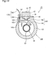
14 ist eine Schnittansicht, die schematisch einen Teil einer Elektrobremse gemäß einer sechsten Ausführungsform der vorliegenden Erfindung zeigt. 14 FIG. 10 is a sectional view schematically showing a part of an electric brake according to a sixth embodiment of the present invention. FIG.
15 ist eine Schnittansicht, die schematisch eine Elektrobremse gemäß einer sieben Ausführungsform der vorliegenden Erfindung zeigt. 15 FIG. 10 is a sectional view schematically showing an electric brake according to a seventh embodiment of the present invention. FIG.
16 ist eine Schnittansicht, die entlang der Linie Y-Y in 15 gezeigt ist. 16 is a sectional view taken along the line YY in 15 is shown.
17 ist eine Schnittansicht entsprechend 16, die zeigt, wie ein Werkzeug verwendet wird. 17 is a sectional view corresponding 16 showing how a tool is used.
AUSFÜHRLICHE BESCHREIBUNG DER ERFINDUNGDETAILED DESCRIPTION OF THE INVENTION
Unter Bezugnahme auf 1 bis 5 wird nachfolgend eine Elektrobremse gemäß einer ersten Ausführungsform der vorliegenden Erfindung beschrieben. In 1 bis 4 umfasst eine Elektrobremse 1 einen Sattel 4, der durch einen Träger 3 gelagert ist, der an einem Nichtrotationsabschnitt eines Fahrzeugkörpers an einer Innenseite des Fahrzeugkörpers in Bezug auf einen Scheibenrotor befestigt ist. Der Sattel 4 ist in einem solchen Zustand gelagert, dass er zu einer Schwimmbewegung in einer Axialrichtung des Scheibenrotors 2 in der Lage ist. Ein Paar von Bremsbelägen 5 und 6 sind derart vorgesehen, um einander zugewandt zu sein, wobei der Scheibenrotor 2 dazwischen vorgesehen ist. Die Bremsbeläge 5 und 6 sind durch den Träger 3 auf solche Weise gelagert, um eine Bewegung der Bremsbeläge 5 und 6 in der Axialrichtung des Scheibenrotors 2 zu ermöglichen.With reference to 1 to 5 An electric brake according to a first embodiment of the present invention will be described below. In 1 to 4 includes an electric brake 1 a saddle 4 that by a carrier 3 mounted on a non-rotating portion of a vehicle body on an inner side of the vehicle body with respect to a disc rotor. The saddle 4 is stored in such a state that it floats in an axial direction of the disc rotor 2 be able to. A pair of brake pads 5 and 6 are provided so as to face each other, wherein the disc rotor 2 is provided in between. The brake pads 5 and 6 are through the carrier 3 stored in such a way to a movement of the brake pads 5 and 6 in the axial direction of the disc rotor 2 to enable.
Der Sattel 4 umfasst ein Klauenelement 9 und einen Sattelkörper 10, der mit dem Klauenelement 9 verbunden ist. Das Klauenelement 9 umfasst ein Klauenabschnitt 7, der an einem vorderen Ende davon gebildet ist, und einen ringförmigen Basiskörper 8, der an einem Basisende davon gebildet ist. Der Klauenabschnitt 7 ist derart vorgesehen, um dem Bremsbelag 6 an einer Außenseite des Fahrzeugkörpers zugewandt zu sein. Der Sattelkörper 10 umfasst einen ringförmigen Körper 11, der mit dem ringförmigen Basiskörper 8 des Klauenelements 9 verbunden ist, und ein Motorgehäuse 12, das mit dem ringförmigen Körper 11 verbunden ist. Das Motorgehäuse 12 umfasst einen Motorgehäusekörper 13 in einer zylindrischen Form, der mit dem ringförmigen Körper 11 verbunden ist, eine Motorendplatte 14, die ein Öffnungsende des Motorgehäusekörpers 13 bedeckt, und ein Gehäuse 16, das in einem Abschnitt 13a einer Seitenwand des Motorgehäusekörpers 13 vorgesehen ist, in welchem ein Loch 15 gebildet ist (der Abschnitt 13a wird nachfolgend als ”Lochbildungsabschnitt 13a” bezeichnet). The saddle 4 includes a claw member 9 and a caliper body 10 that with the claw element 9 connected is. The claw element 9 includes a claw portion 7 formed at a front end thereof and an annular base body 8th which is formed at a base end thereof. The claw section 7 is provided so as to the brake pad 6 to be facing on an outside of the vehicle body. The caliper body 10 comprises an annular body 11 that with the annular base body 8th of the claw element 9 is connected, and a motor housing 12 that with the annular body 11 connected is. The motor housing 12 includes a motor housing body 13 in a cylindrical shape coinciding with the annular body 11 is connected, a motor end plate 14 , which is an opening end of the motor housing body 13 covered, and a housing 16 that in a section 13a a side wall of the motor housing body 13 is provided, in which a hole 15 is formed (the section 13a is hereinafter referred to as "hole forming section 13a " designated).
In dem Sattel 4 sind ein Kolben 20 mit trennbaren Teilen, der dazu ausgelegt ist, den Bremsbelag 5 (auf einer inneren Seite des Fahrzeugskörpers) gegen den Scheibenrotor 2 zu drücken, ein Motor 21, ein Kugelrampenmechanismus (ein Dreh-Linearbewegungs-Wandelmechanismus) 22 zum Ermöglichen, dass eine Rotation des Motors in eine Linearbewegung gewandelt und auf den Kolben 20 übertragen wird, ein Differentialuntersetzungsmechanismus 23 zum Ermöglichen, dass die Rotation des Motors 21 untersetzt und auf den Kugelrampenmechanismus 22 übertragen wird, ein Belagverschleißausgleichsmechanismus 24 zum Ausgleichen eines Verschleißbetrages der Bremsbeläge 5 und 6 durch Verändern einer Position des Kolbens 20 in Bezug auf den Verschleißbetrag, und ein Parkbremsmechanismus 25 zum Sichern der Parkbremse vorgesehen. Der Sattel 4 ist ebenso mit einem Aktor 60 ausgestattet, der dazu ausgelegt ist, einen Betrieb des Parkbremsmechanismus 25 zwischen Verriegelungswirkung und einer Entriegelungswirkung durch selektives Zuführen von Strömen unterschiedlicher Polaritäten zu dem Parkbremsmechanismus 25 für eine kurze Zeitdauer umzuschalten.In the saddle 4 are a piston 20 with separable parts, which is designed to protect the brake pad 5 (on an inner side of the vehicle body) against the disc rotor 2 to push a motor 21 , a ball ramp mechanism (a rotary-linear motion change mechanism) 22 to allow a rotation of the motor to be converted into a linear motion and to the piston 20 is transmitted, a differential reduction mechanism 23 to allow the rotation of the engine 21 stocky and on the ball ramp mechanism 22 is transmitted, a pad wear compensation mechanism 24 for compensating a wear amount of the brake pads 5 and 6 by changing a position of the piston 20 in terms of wear amount, and a parking brake mechanism 25 provided for securing the parking brake. The saddle 4 is also with an actor 60 equipped, which is adapted to an operation of the parking brake mechanism 25 between locking action and unlocking action by selectively supplying currents of different polarities to the parking brake mechanism 25 switch for a short period of time.
Der Kugelrampenmechanismus 22 umfasst eine erste Scheibe 27 in einer ringartigen Form, die schwenkbar durch eine innere Umfangsfläche eines Verbindungsabschnitts des ringförmigen Basiskörpers 8 und des ringförmigen Körpers 11 des Sattels 4 durch ein Lager 26 gelagert ist, eine zweite Scheibe 29 in einer ringartigen Form, die einen inneren Raum besitzt und mit einem zylindrischen Abschnitt 28 des Kolbens 20 verbunden ist, der in den inneren Raum eingefügt ist, und Kugeln 30, die zwischen den Scheiben 27 und 29 vorgesehen sind. Die zweite Scheibe 29 ist gehalten, während sie zum Rotieren niedergedrückt ist. Die zweite Scheibe 29 ist dazu ausgelegt, eine Rotationskraft, die sie von der ersten Scheibe 27 über die Kugeln 30 erhält, in eine Linearbewegung umzuwandeln und die Linearbewegung auf den Kolben 20 zu übertragen.The ball ramp mechanism 22 includes a first disc 27 in an annular shape pivotable by an inner peripheral surface of a connecting portion of the annular base body 8th and the annular body 11 of the saddle 4 through a warehouse 26 is stored, a second disc 29 in a ring-like shape having an internal space and having a cylindrical portion 28 of the piston 20 connected to the inner space and balls 30 between the discs 27 and 29 are provided. The second disc 29 is held while it is depressed to rotate. The second disc 29 is designed to give a rotational force to it from the first disc 27 over the balls 30 gets to convert into a linear motion and the linear motion on the piston 20 transferred to.
Der Kolben 20 umfasst die trennbaren Teile, das heißt den zylindrischen Abschnitt 28 und einen Kolbenkörper 31 mit einem größeren Durchmesser als der zylindrische Abschnitt 28. Der Kolbenkörper 31 ist dazu ausgelegt, eine Kraft von dem zylindrischen Abschnitt 28 und somit dem Kugelrampenmechanismus 22 (und somit dem Motor 21) aufzunehmen. Der zylindrische Abschnitt 28 ist durch einen Lagerzylinder 35 (der später beschrieben wird) über ein Kolbenbetätigungselement (hierfür ist kein Bezugszeichen angegeben) gelagert, während er an einer Rotation gehindert wird. Ein Reaktionskraftsensor 33 ist zwischen dem Kolbenkörper 31 und einem geschlossenen Ende 32 eines hohlen Abschnitts, der in dem zylindrischen Abschnitt 28 auf einer Seite des Kolbenkörpers 31 gebildet ist, derart vorgesehen, um eine Reaktionskraft von dem Kolbenkörper 31 zu erfassen. Ein Signaldraht 34 des Reaktionskraftsensors 33 ist durch die Lagerzylinder 35 hindurch eingefügt und mit einem Controller 40 verbunden, der in dem Fahrzeugkörper vorgesehen ist. Der Lagerzylinder 35 ist durch das Motorgehäuse 12 über ein zylindrisches Lagerelement 41 gelagert.The piston 20 includes the separable parts, that is the cylindrical section 28 and a piston body 31 with a larger diameter than the cylindrical section 28 , The piston body 31 is designed to be a force from the cylindrical portion 28 and thus the ball ramp mechanism 22 (and thus the engine 21 ). The cylindrical section 28 is through a bearing cylinder 35 (which will be described later) via a piston actuator (this is not indicated) is supported while being prevented from rotating. A reaction force sensor 33 is between the piston body 31 and a closed end 32 a hollow portion formed in the cylindrical portion 28 on one side of the piston body 31 is formed, provided so as to a reaction force of the piston body 31 capture. A signal wire 34 of the reaction force sensor 33 is through the bearing cylinder 35 inserted through and with a controller 40 connected, which is provided in the vehicle body. The bearing cylinder 35 is through the motor housing 12 via a cylindrical bearing element 41 stored.
Der Motor 21 umfasst einen Stator 43, der in einer eingepassten Beziehung zu dem Motorgehäuse 12 befestigt ist, und einen Rotor 44 mit einer hohlen Struktur, der innerhalb des Stators 43 vorgesehen ist. Der Rotor 44 ist rotierbar durch das Motorgehäuse 12 gelagert. Der Motor 21 wird entsprechend einem Befehlssignal von dem Controller 40 derart betrieben, um den Rotor 44 um einen gewünschten Winkel mit einem gewünschten Drehmoment zu rotieren. Der Rotationswinkel des Rotors 44 wird durch einen Positionsdetektor 42 (wie einen Resolver (Drehmelder)), der in dem Rotor 44 vorgesehen ist, erfasst. In dieser Ausführungsform rotiert der Rotor in Antwort auf ein Befehlssignal von dem Controller 40 zum Erzeugen einer Bremskraft den Rotor 44 in einer Richtung L entgegen des Uhrzeigersinns in 2. Der Controller 40 steuert nicht nur den Motor 21, sondern auch den Aktor 60, und somit den Parkbremsmechanismus 25, über eine Antriebsschaltung 70.The motor 21 includes a stator 43 which is in a fitted relationship with the engine housing 12 is attached, and a rotor 44 with a hollow structure inside the stator 43 is provided. The rotor 44 is rotatable by the motor housing 12 stored. The motor 21 is in accordance with a command signal from the controller 40 so operated around the rotor 44 to rotate at a desired angle with a desired torque. The rotation angle of the rotor 44 is through a position detector 42 (like a resolver) in the rotor 44 is envisaged. In this embodiment, the rotor rotates in response to a command signal from the controller 40 for generating a braking force the rotor 44 in a counterclockwise direction L in FIG 2 , The controller 40 not only controls the engine 21 but also the actor 60 , and thus the parking brake mechanism 25 , via a drive circuit 70 ,
Wie in 1 und 2 gezeigt, umfasst der Parkbremsmechanismus 25 eine Sperrklinke 50 (einen zugehörigen Bewegungsabschnitt), der mit dem Rotor 44 des Motors 21 verbunden ist und der in Verknüpfung mit dem Motor arbeitet, und einen Schwenkarm 52, der an einem Umfang der Sperrklinke 50 vorgesehen ist, wobei ein Basisende (das nicht mit einem Bezugszeichen versehen ist) des Schwenkarms 52 schwenkbar an dem Sattelkörper 10 unter Einsatz eines Stifts 51 angebracht ist. Ein äußerer Umfangsabschnitt der Sperrklinke 50 ist integral mit einer Mehrzahl von Zahnabschnitten 57 gebildet. Ein zugehöriger Bewegungsabschnitt, der in Verknüpfung mit den Motor arbeitet, ist nicht auf die Sperrklinke 50 beschränkt. Der zugehörige Bewegungsabschnitt kann durch Bilden einer Mehrzahl von Zahnabschnitten 57 integral mit einem äußeren Umfangsabschnitt des Rotors 44 des Motors 21 vorgesehen werden, falls es ausreichend Raum gibt. Alternativ kann der zugehörige Bewegungsabschnitt durch ein bewegliches Bauteil des Differentialuntersetzungsmechanismus 23 oder des Kugelrampenmechanismus (Dreh-Linearbewegungs-Wandelmechanismus) 22 gebildet sein, da es in Verknüpfung mit dem Motor arbeitet. Das heißt, der zugehörige Bewegungsabschnitt kann durch jegliches Bauteil gebildet sein, das in der Lage ist, einen Eingriffseinschnitt wie einen Zahnabschnitt zu bilden.As in 1 and 2 shown, includes the parking brake mechanism 25 a pawl 50 (an associated movement section) connected to the rotor 44 of the motor 21 is connected and which works in conjunction with the engine, and a swivel arm 52 attached to a perimeter of the pawl 50 is provided, wherein a base end (which is not provided with a reference numeral) of the pivot arm 52 pivotable on the caliper body 10 using a pen 51 is appropriate. One outer peripheral portion of the pawl 50 is integral with a plurality of tooth sections 57 educated. An associated section of motion that works in conjunction with the engine is not on the pawl 50 limited. The associated moving portion can be formed by forming a plurality of tooth portions 57 integral with an outer peripheral portion of the rotor 44 of the motor 21 be provided if there is sufficient space. Alternatively, the associated movement portion may be formed by a movable member of the differential reduction mechanism 23 or the ball ramp mechanism (rotary-linear motion change mechanism) 22 be formed, since it works in conjunction with the engine. That is, the associated movement portion may be formed by any member capable of forming an engagement groove such as a tooth portion.
Eine Eingriffsklaue 54 ist schwenkbar über einen Stift 53 mit einem im wesentlichen mittig gelegenen Abschnitt in einer Längsrichtung des Schwenkarms 52 verbunden. Ein vorderer Endabschnitt (nachfolgend als ”vorderer Endabschnitt der Eingriffsklaue” bezeichnet) 54a ist mit den Zahnabschnitten 57 in Eingriff bringbar. Ein Flansch (nachfolgend als ”Schwenkarmflansch” bezeichnet) 52a ist in einem im wesentlichen mittig gelegenen Abschnitt des Schwenkarms 52 gebildet. Der Schwenkarmflansch 52a erstreckt sich in einer Richtung orthogonal zu der Längsrichtung des Schwenkarms 52. Der Schwenkarmflansch 52a umfasst ein Langloch (nachfolgend als ”Schwenkarmflanschlangloch” bezeichnet) 52b darin, das sich in der Längsrichtung des Schwenkarms 52 erstreckt.An engagement claw 54 is pivotable over a pin 53 with a substantially central portion in a longitudinal direction of the swing arm 52 connected. A front end portion (hereinafter referred to as "front end portion of the engagement claw") 54a is with the teeth sections 57 engageable. A flange (hereinafter referred to as "swing arm flange") 52a is in a substantially central portion of the swing arm 52 educated. The swivel arm flange 52a extends in a direction orthogonal to the longitudinal direction of the pivot arm 52 , The swivel arm flange 52a includes a slot (hereinafter referred to as "swing arm flange slot") 52b in it, extending in the longitudinal direction of the swivel arm 52 extends.
Der Parkbremsmechanismus 25 umfasst ferner eine feste Feder 58, die stets die Eingriffsklaue 54 in einer Richtung nach links in 2 vorspannt, einen Vorsprung 59, der an dem Schwenkarm 52 befestigt ist und mit der festen Feder 58 zusammenwirkt, um die Eingriffsklaue 54 in einer aufrechten Position zu halten, welche einen Eingriff zwischen der Eingriffsklaue 54 und der Sperrklinke 50 ermöglicht, und eine Ausdehnungsfeder 61, die ein Ende (ein vorderes Ende; hierfür ist kein Bezugszeichen vergeben) des Schwenkarms 52 auf einer dem Basisende hiervon gegenüberliegenden Seite in einer Richtung nach unten in 2 vorspannt.The parking brake mechanism 25 further comprises a fixed spring 58 that are always the engaging claw 54 in a left direction in 2 pretensions, a lead 59 that is on the swivel arm 52 is fixed and with the fixed spring 58 cooperates to the engagement claw 54 to hold in an upright position, which is an engagement between the engagement claw 54 and the pawl 50 allows, and an expansion spring 61 having one end (a front end, for which no reference numeral is assigned) of the pivot arm 52 on a side opposite the base end thereof in a downward direction in FIG 2 biases.
Jeder Zahnabschnitt 57 der Sperrklinke 50 ist im wesentlichen in der Form einer umgekehrten V-Form mit einer Zahnfläche 57a und einer Zahnfläche 57b. Die Zahnfläche 57a des Zahnabschnitts 57 ist in Bezug auf eine Rotationsrichtung R des Rotors 44 zum Lösen der Bremse (einer Richtung im Uhrzeigersinn in 2) nach vorne gewandt, und die Zahnfläche 57b ist in Bezug auf eine Rotationsrichtung L des Rotors 44 zum Aufbringen der Bremse (einer Richtung entgegen des Uhrzeigersinns in 2) nach vorne gewandt. In diesem Falle ist die Zahnfläche 57a auf solche Weise ausgeformt, dass sie sich im wesentlichen in einer radialen Richtung des Rotors 44 erstreckt, das heißt eine die Zahnfläche 57a enthaltende Ebene enthält die Mittelachse des Rotors 44 (die Mittelachse C der Sperrklinke 50).Every tooth section 57 the pawl 50 is substantially in the form of an inverted V-shape with a tooth surface 57a and a tooth surface 57b , The tooth surface 57a of the tooth section 57 is with respect to a rotational direction R of the rotor 44 for releasing the brake (one direction clockwise in 2 ) turned to the front, and the tooth surface 57b is with respect to a rotational direction L of the rotor 44 for applying the brake (counterclockwise direction in FIG 2 ) turned to the front. In this case, the tooth surface 57a formed in such a way that they are substantially in a radial direction of the rotor 44 extends, that is one the tooth surface 57a containing plane contains the central axis of the rotor 44 (The center axis C of the pawl 50 ).
Der Aktor 60 umfasst ein Aktorgehäuse 62, ein Kolbenlagerelement 65, einen Dauermagneten 66 und eine Spule 67. Das Aktorgehäuse 62 besitzt im wesentlichen eine hutartige Konfiguration und ist an dem Lochbildungsabschnitt 13a des Motorgehäusekörpers 13 derart befestigt, um das Loch 15 abzudecken. Das Kolbenlagerelement 65 ist an dem Aktorgehäuse 62 derart montiert, dass es in einer Öffnung (für die kein Bezugszeichen vergeben ist) eines Hohlraums 63 des Aktorgehäuses 62 vorgesehen ist. Ein Kolben 64 ist durch das Kolbenlagerelement 65 hindurch eingefügt und ist in der Axialrichtung des Kolbens 64 (einer vertikalen Richtung in 2) als Verschiebungsrichtung des Kolbens 64 beweglich. Der Dauermagnet 66 ist an dem Kolbenlagerelement 65 auf einer Seite des Hohlraums 63 vorgesehen. Die Spule 67 ist im Hohlraum 63 aufgenommen. Der Dauermagnet 66 bildet ein Solenoid vom Selbsthaltetyp durch Ausüben einer Anziehungskraft auf den Kolben 64, wodurch eine Bewegung des Kolbens 64 in einer Richtung nach unten in 2 unterdrückt wird.The actor 60 includes an actuator housing 62 , a piston bearing element 65 , a permanent magnet 66 and a coil 67 , The actuator housing 62 has a hat-shaped configuration substantially and is at the hole forming portion 13a of the motor housing body 13 so fastened to the hole 15 cover. The piston bearing element 65 is on the actuator housing 62 mounted so as to be in an opening (for which no reference numeral is assigned) of a cavity 63 of the actuator housing 62 is provided. A piston 64 is through the piston bearing element 65 inserted and is in the axial direction of the piston 64 (a vertical direction in 2 ) as the displacement direction of the piston 64 movable. The permanent magnet 66 is on the piston bearing element 65 on one side of the cavity 63 intended. The sink 67 is in the cavity 63 added. The permanent magnet 66 Forms a self-holding type solenoid by exerting an attraction force on the piston 64 , causing a movement of the piston 64 in a downward direction 2 is suppressed.
Die Spule 67 wird mit Strömen unterschiedlicher Polaritäten versorgt, um hierdurch eine elektromagnetische Kraft für den Kolben 64 entsprechend der Polarität des zugeführten Stromes zu erzeugen. Die Spule 67 ist in der Lage, eine Anziehungskraft des Dauermagneten 66 aufzuheben, um hierdurch die Bewegung des Kolbens 64 in der Richtung nach unten in 2 zu ermöglichen (und somit eine Aufrechterhaltung der Aufbringung der Bremskraft zu ermöglichen). Die Spule 67 ist ebenso in der Lage, eine Anziehungskraft auf den Kolben 64 auszuüben, der in der Richtung nach unten in 2 bewegt worden ist, und zwar infolge der Wirkung der erzeugten elektromagnetischen Kraft, und somit eine Bewegung des Kolbens 64 in einer Richtung nach oben in 2 zu ermöglichen (und somit das Lösen der Parkbremse zu ermöglichen).The sink 67 is supplied with currents of different polarities to thereby produce an electromagnetic force for the piston 64 to produce according to the polarity of the supplied current. The sink 67 is capable of attracting the permanent magnet 66 to cancel, thereby the movement of the piston 64 in the direction down in 2 to allow (and thus to allow the application of the braking force). The sink 67 is also capable of attracting the piston 64 exercise in the direction down in 2 has been moved, due to the effect of the generated electromagnetic force, and thus a movement of the piston 64 in a direction up in 2 to allow (and thus to enable the release of the parking brake).
Der Kolben 64 ist in einem solchen Zustand vorgesehen, dass eine Achse davon zu der Mittelachse C der Sperrklinke 50 gerichtet ist. Ein vorderer Endabschnitt (für den kein Bezugszeichen vergeben ist) des Kolbens 64 ist mit dem Schwenkarm 52 durch einen Stift 68 verbunden, der durch das Schwenkarmflanschlangloch 52b eingefügt ist. Wenn der Kolben 64 sich in einer vertikalen Richtung in 2 bewegt, wird der Schwenkarm 52 schwenkend um den Stift 51 entsprechend der Bewegung des Kolbens 64 bewegt, um ein Ineingriffbringen und Lösen zwischen der Eingriffsklaue 54 und der Sperrklinke 50 zu bewirken. In dieser Ausführungsform sind der Stift 68, das Schwenkarm 52, die Eingriffsklaue 54, die feste Feder 58 und die Ausdehnungsfeder 61 vorgesehen, um eine Eingriffsstruktur bereitzustellen.The piston 64 is provided in such a state that an axis thereof to the center axis C of the pawl 50 is directed. A front end portion (for which no reference numeral is assigned) of the piston 64 is with the swivel arm 52 through a pen 68 connected by the Schwenkarmflanschlangloch 52b is inserted. When the piston 64 in a vertical direction in 2 moves, becomes the swivel arm 52 waving around the pen 51 according to the movement of the piston 64 moved to engage and disengage between the engagement claw 54 and the pawl 50 to effect. In this embodiment, the pen 68 . the swivel arm 52 , the engaging claw 54 , the solid spring 58 and the expansion spring 61 provided to provide an engagement structure.
Ein Schraubenloch 120 (eine Öffnung zum Einfügen eines Kraftaufbringelements zum Aufbringen einer Kraft auf den Kraftaufnahmeabschnitt) ist an einem linken oberen Abschnitt des zylindrischen Motorgehäusekörpers 13 (Gehäuse) betrachtet in 2 gebildet. Eine wasserdichte Schraube 121, die als Kappenelement dient, ist gewindemäßig mit dem Schraubenloch 120 in Eingriff. Das Schraubenloch 120 ist derart ausgeformt, dass eine Ausdehnungslinie der Mittelachse des Schraubenlochs 120 im wesentlichen orthogonal zu der Verschiebungsrichtung des Kolbens 64 ist. Der Stift 68 ist auf dieser Ausdehnungslinie gelegen. In dieser Ausführungsform ist ein Werkzeug 122 (ein Kraftaufbringelement) vorgesehen. Das Werkzeug 122 besitzt ein ausreichende Länge, um den Stift 68 zu erreichen, wenn das Werkzeug 122 durch das Schraubenloch 120 eingefügt ist. Das Werkzeug 122 umfasst einen stabartigen Werkzeugkörper 123, einen vorderen Werkzeugendabschnitt 124, der an einem Ende des Werkzeugkörpers 123 gebildet ist, und einen Greifabschnitt 125, der an dem anderen Ende des Werkzeugkörpers 123 vorgesehen ist. Der vordere Werkzeugendabschnitt 124 bildet einen geneigten Abschnitt, der im wesentlichen in der Form eines Kegelstumpfes ist.A screw hole 120 (An opening for inserting a force applying member for applying a force to the force receiving portion) is at a left upper portion of the cylindrical motor housing body 13 (Housing) considered in 2 educated. A watertight screw 121 , which serves as a cap member, is threaded with the screw hole 120 engaged. The screw hole 120 is formed such that an extension line of the center axis of the screw hole 120 substantially orthogonal to the direction of displacement of the piston 64 is. The pencil 68 is located on this stretch line. In this embodiment is a tool 122 (A force application element) is provided. The tool 122 has sufficient length to the pin 68 to reach when the tool 122 through the screw hole 120 is inserted. The tool 122 includes a rod-like tool body 123 , a front tool end portion 124 which is at one end of the tool body 123 is formed, and a gripping portion 125 at the other end of the tool body 123 is provided. The front tool end section 124 forms a sloped portion which is substantially in the shape of a truncated cone.
Um das Werkzeug 122 zu verwenden, wird der Greifabschnitt 125 des Werkzeugs gehalten, und das Werkzeug wird, wie in 2 gezeigt, in das Schraubenloch 120 eingefügt, von welchem die wasserdichte Schraube 121 entnommen worden ist. Das Werkzeug 122 wird eingefügt, bis der vordere Werkzeugendabschnitt 124 eine untere Fläche 68a (einen Kraftaufnahmeabschnitt) des Stifts 68 erreicht. Wenn der vordere Werkzeugendabschnitt 124 die untere Fläche 68a erreicht, nimmt die untere Fläche 68a und somit der Stift 68 eine nach oben gerichtete Kraft (betrachtet in 2) von dem Werkzeug 122 auf. Durch weiteres Einfügen des Werkzeugs 122 durch das Schraubenloch 120, wie in 5 angegeben, bewegt sich der Stift 68 nach oben (betrachtet in 2) entlang einer geneigten Fläche des vorderen Werkzeugendabschnitts 124. Dementsprechend bewegt sich der Schwenkarm 52 schwenkend um den Stift 51 in einer Richtung entgegen des Uhrzeigersinns in 2.To the tool 122 to use, becomes the gripping section 125 held the tool, and the tool will, as in 2 shown in the screw hole 120 inserted, from which the watertight screw 121 has been removed. The tool 122 is inserted until the front tool end section 124 a lower surface 68a (a force receiving portion) of the pen 68 reached. When the front tool end section 124 the lower surface 68a reaches, takes the bottom surface 68a and thus the pen 68 an upward force (considered in 2 ) of the tool 122 on. By further insertion of the tool 122 through the screw hole 120 , as in 5 indicated, moves the pen 68 upwards (considered in 2 ) along an inclined surface of the front tool end portion 124 , Accordingly, the swing arm moves 52 waving around the pen 51 in a counterclockwise direction in FIG 2 ,
Die Spule 67 ist über ein Kabel 126 mit der mit dem Controller 40 verbundenen Antriebsschaltung 70 und einer Batterie 49 verbunden. In dieser Ausführungsform wird durch Zuführen eines Stromes in einer Richtung der Spule 67 die Spule 67 veranlasst, eine elektromagnetische Kraft zu erzeugen, die in einer Richtung zum Aufheben der Anziehungskraft des Dauermagneten 66 wirkt (eine Kraft, welche einen unverriegelten Zustand des Parkbremsmechanismus 25 aufrecht erhält). Dieser Strom in einer Richtung wird nachfolgend als ”erster vorbestimmter Strom” bezeichnet. Durch Versorgen der Spule 67 mit dem ersten vorbestimmten Strom für eine kurze Zeitdauer wird der unverriegelte Zustand des Parkbremsmechanismus 25 gelöst. Danach wird der Parkbremsmechanismus 25 infolge der Wirkung einer Vorspannkraft der Ausdehnungsfeder 61 in einen verriegelten Zustand gesetzt.The sink 67 is over a cable 126 with the one with the controller 40 connected drive circuit 70 and a battery 49 connected. In this embodiment, by supplying a current in one direction of the coil 67 the sink 67 caused to generate an electromagnetic force in a direction to cancel the attraction of the permanent magnet 66 acts (a force which is an unlocked state of the parking brake mechanism 25 maintains). This unidirectional flow is hereinafter referred to as "first predetermined current". By supplying the coil 67 with the first predetermined current for a short period of time becomes the unlocked state of the parking brake mechanism 25 solved. Thereafter, the parking brake mechanism 25 due to the action of a biasing force of the expansion spring 61 set to a locked state.
Wenn die Spule 67 mit einem Strom in einer Richtung versorgt wird, welche der Richtung des ersten vorbestimmten Stromes entgegengesetzt ist (nachfolgend als ”zweiter vorbestimmter Strom” bezeichnet), erzeugt die Spule 67 eine elektromagnetische Kraft, die entgegen einer Zugkraft der Ausdehnungsfeder 61 wirkt, das heißt eine elektromagnetische Kraft, die in einer Richtung zum Aufheben einer Kraft zum Halten des Kolbens 64 wirkt (eine Kraft, die einen verriegelten Zustand des Parkbremsmechanismus 25 aufrecht erhält). Diese elektromagnetische Kraft oder eine Gesamtheit dieser elektromagnetischen Kraft und der Anziehungskraft des Dauermagneten 66 ist größer eingestellt als die Zugkraft der Ausdehnungsfeder 61. Die Vorsprungkraft der Ausdehnungsfeder 61 ist geringer eingestellt eine Gesamtheit der Anziehungskraft des Dauermagneten 66 und der Anziehungskraft, die erzeugt wird, wenn der zweite vorbestimmte Strom zu der Spule 67 für eine kurze Zeitdauer zugeführt wird. Durch Versorgen der Spule 67 mit dem zweiten vorbestimmten Strom wird der verriegelte Zustand des Parkbremsmechanismus 25 gelöst.If the coil 67 is supplied with a current in a direction opposite to the direction of the first predetermined current (hereinafter referred to as "second predetermined current") generates the coil 67 an electromagnetic force that opposes a tensile force of the expansion spring 61 that is, an electromagnetic force acting in a direction to cancel a force to hold the piston 64 acts (a force that is a locked state of the parking brake mechanism 25 maintains). This electromagnetic force or a whole of this electromagnetic force and the attraction of the permanent magnet 66 is set larger than the tensile force of the expansion spring 61 , The projection force of the expansion spring 61 is set lower a totality of the attraction of the permanent magnet 66 and the attraction force that is generated when the second predetermined current to the coil 67 for a short period of time. By supplying the coil 67 with the second predetermined current becomes the locked state of the parking brake mechanism 25 solved.
In der Elektrobremse 1 ist in einem Ausgangszustand die Spule 67 nicht mit Energie beaufschlagt, und der Dauermagnet 66 übt eine Anziehungskraft auf den Kolben 64 aus. In diesem Zustand ist die Eingriffsklaue 54 etwas von den Zahnabschnitten 57 der Sperrklinke 50 beabstandet.In the electric brake 1 is in an initial state, the coil 67 not energized, and the permanent magnet 66 exerts an attraction on the piston 64 out. In this condition is the engagement claw 54 something from the teeth sections 57 the pawl 50 spaced.
Nachfolgend wird der Betrieb der wie oben erläutert aufgebauten Elektrobremse 1 beschrieben. Es gibt vier Betriebsarten, nämlich (1a) ein Betrieb zum Aufbringen der normalen Bremse, (1b) ein Betrieb zum Lösen der normalen Bremse, (2a) ein Betrieb zum Aufbringen der Parkbremse, (2b) ein Betrieb zum Lösen der Parkbremse und (3) ein Betrieb zum manuellen Lösen der Parkbremse.
- (1a) Betrieb zum Aufbringen der normalen Bremse:
zum normalen Bremsen, bei welchem die Elektrobremse betätigt wird, wird der Rotor 44 des Motors 21 in der Richtung L entgegen des Uhrzeigersinns in 2 entsprechend einer auf das Bremspedal aufgebrachten Fahrerkraft rotiert. Dementsprechend drückt (schiebt) der Kolben 20 nach vorne, wodurch eine Bremskraft entsprechend einem Drehmoment des Motors 21 erzeugt wird.
Hereinafter, the operation of the electric brake constructed as explained above will be described 1 described. There are four modes, namely, (1a) a normal brake applying operation, (1b) a normal brake release operation, (2a) a parking brake applying operation, (2b) a parking brake releasing operation, and (3 ) an operation for manually releasing the parking brake. - (1a) Operation for Applying the Normal Brake: For normal braking in which the electric brake is operated, the rotor becomes 44 of the motor 21 in the counterclockwise direction L in FIG 2 rotates according to a force applied to the brake pedal driver. Accordingly, the piston pushes (pushes) 20 forward, thereby providing a braking force corresponding to a torque of the engine 21 is produced.
Während des normalen Bremsens ist die Spule 67 nicht mit Energie beaufschlagt, und der Dauermagnet 66 übt eine Anziehungskraft auf den Kolben 64 aus. Daher ist die Eingriffsklaue 54 in einer etwas beabstandeten Beziehung zu den Zahnabschnitten 57 der Sperrklinke 50. Daher wird der Rotor 44 sanft in der Richtung L entgegen des Uhrzeigersinns rotiert, und es wird eine normale Bremsfunktion zufriedenstellend ausgeübt. During normal braking is the coil 67 not energized, and the permanent magnet 66 exerts an attraction on the piston 64 out. Therefore, the engagement claw 54 in a slightly spaced relationship with the teeth sections 57 the pawl 50 , Therefore, the rotor becomes 44 gently rotates in the counterclockwise direction L, and a normal braking function is satisfactorily performed.
In diesem Falle wird der Rotor 44 rotiert, wobei die Eingriffsklaue 54 von den Zahnabschnitten 57 der Sperrklinke 50 beabstandet ist. Daher kann die Erzeugung eines ausgeprägten Geräusches verhindert werden, und die Verschleißrate kann vermindert werden, so dass der Motor 21 mit einer hohen Effizienz betrieben werden kann.
- (1b) Betrieb zum Lösen der normalen Bremse:
zum Lösen der normalen Bremse wird der Rotor 44 des Motors 21 in der Richtung R im Uhrzeigersinn in 2 rotiert, und zwar entsprechend einer Fahrerbetätigung zum Lösen des Bremspedals. Der Kolben 20 wird zurückgezogen, und somit wird die Bremse gelöst. Dabei wird ein nicht mit Energie beaufschlagter Zustand der Spule 67 aufrecht erhalten, so dass der Dauermagnet 66 eine Anziehungskraft auf den Kolben 64 ausübt. Daher wird die Eingriffsklaue 54 in einer beabstandeten Beziehung zu den Zahnabschnitten 57 der Sperrklinke 50 gehalten, und die Sperrklinke 50 rotiert sanft mit dem Rotor 44 in der Richtung R im Uhrzeigersinn in 2, ohne ein Kontakt zu der Eingriffsklaue 54 herzustellen. Somit kann ein Lösen der normalen Bremse sichergestellt werden.
- (2a) Betrieb zum Aufbringen der Parkbremse:
zum Aufbringen der Parkbremse wird der Rotor 44 des Motors 21 in der Richtung L entgegen des Uhrzeigersinns in 2 rotiert, und zwar entsprechend der Betätigung zum Aufbringen der Parkbremse durch einen Fahrer. Wie im Falle des normalen Bremsens schiebt der Kolben 20 nach vorne, um hierdurch eine Bremskraft zu erzeugen. Dann wird ein erster vorbestimmter Strom zu der Spule 67 für eine kurze Zeitdauer zugeführt, während annähernd gleichzeitig die Bremskraft ein vorbestimmtes Niveau erreicht. Danach wird der Motor 21 von der Energie getrennt.
In this case, the rotor 44 rotated, with the engagement claw 54 from the teeth sections 57 the pawl 50 is spaced. Therefore, the generation of a pronounced noise can be prevented, and the wear rate can be reduced so that the engine 21 can be operated with a high efficiency. - (1b) Normal brake release operation: the rotor is released to release the normal brake 44 of the motor 21 in the direction R clockwise in 2 rotates, according to a driver operation to release the brake pedal. The piston 20 is retracted, and thus the brake is released. This is a not energized state of the coil 67 maintained so that the permanent magnet 66 an attraction to the piston 64 exercises. Therefore, the engagement claw becomes 54 in a spaced relation to the tooth sections 57 the pawl 50 held, and the pawl 50 gently rotates with the rotor 44 in the direction R clockwise in 2 without contact with the engagement claw 54 manufacture. Thus, a release of the normal brake can be ensured.
- (2a) Operation for applying the parking brake: for applying the parking brake is the rotor 44 of the motor 21 in the counterclockwise direction L in FIG 2 rotates, according to the operation for applying the parking brake by a driver. As in the case of normal braking, the piston pushes 20 forward to thereby generate a braking force. Then, a first predetermined current becomes to the coil 67 supplied for a short period of time, while approximately simultaneously, the braking force reaches a predetermined level. After that, the engine becomes 21 separated from the energy.
Infolge der Zufuhr des ersten vorbestimmten Stromes zu der Spule 67 für eine kurze Zeitdauer erzeugt die Spule 67 eine elektromagnetische Kraft, welche die Anziehungskraft des Dauermagneten 66 aufhebt. Dann bewegt sich unter der Vorspannkraft der Ausdehnungsfeder 61 der Schwenkarm 52 schwenkend in der Richtung R im Uhrzeigersinn in 2, während sich der Kolben 64 in einer Richtung nach unten in 2 bewegt. Dementsprechend wird die Eingriffsklaue 54 zu der Sperrklinke 50 verschoben und liegt an dem Zahnabschnitt 57 an und wird unter der Kraft der Ausdehnungsfeder 61 gehalten (verriegelt). In dieser Ausführungsform wird der verriegelte Zustand des Parkbremsmechanismus 25 infolge der Wirkung der Vorspannkraft der Ausdehnungsfeder 61 aufrecht erhalten.As a result of the supply of the first predetermined current to the coil 67 for a short period of time generates the coil 67 an electromagnetic force, which is the attractive force of the permanent magnet 66 picks. Then moves under the biasing force of the expansion spring 61 the swivel arm 52 pivoting in the direction R clockwise in 2 while the piston 64 in a downward direction 2 emotional. Accordingly, the engagement claw becomes 54 to the pawl 50 moved and is located on the tooth section 57 and is under the force of the expansion spring 61 held (locked). In this embodiment, the locked state of the parking brake mechanism 25 due to the effect of the biasing force of the expansion spring 61 maintained.
Wenn der Motor 21 von der Energie getrennt wird, wird infolge der Wirkung der Steifigkeit des Sattels 4 (wie ein Zurückziehen des Kolbens 20 unter einer durch Bremsen erzeugten Reaktionskraft) eine Rotationskraft in der Richtung R im Uhrzeigersinn in dem Rotor 44 des Motors 21 erzeugt. Die Eingriffsklaue 54 wird durch diese Rotationskraft gedrückt, und die Rotation des Rotors 44 in der Richtung R des Uhrzeigersinns wird begrenzt. Als Ergebnis hieraus wird die Parkbremse gesichert.If the engine 21 is separated from the energy is due to the effect of the rigidity of the saddle 4 (like retracting the piston 20 under a reaction force generated by braking), a rotational force in the direction R clockwise in the rotor 44 of the motor 21 generated. The engagement claw 54 is pressed by this rotational force, and the rotation of the rotor 44 in the direction R of clockwise is limited. As a result, the parking brake is secured.
In dieser Ausführungsform ist der erste vorbestimmte Strom als ein Stromwert bestimmt, der ermöglicht, dass die Spule 67 eine elektromagnetische Kraft erzeugt, die in der Lage ist, eine magnetische Kraft des Dauermagneten 66 aufzuheben. Ferner ist in dieser Ausführungsform die kurze Zeitdauer, für welche der erste vorbestimmte Strom zugeführt wird, eine Zeit (100 msec – 1 sec) zwischen einem Zeitpunkt, zu welchem die Energiebeaufschlagung gestartet wird, und einem Zeitpunkt, zu welchem die Spule 67 eine elektromagnetische Kraft erzeugt, welche die Anziehungskraft des Dauermagneten 66 aufhebt.
- (2b) Betrieb zum Lösen der Parkbremse:
zum Lösen der Parkbremse wird der Motor 21 entsprechend einer Betätigung zum Lösen der Parkbremse durch einen Fahrer mit Energie beaufschlagt, um hierdurch den Rotor 44 des Motors 21 etwas in der Richtung L entgegen des Uhrzeigersinns (einer Richtung zum Bremsen) zu rotieren. Gleichzeitig wird der zweite vorbestimmte Strom, der eine Polarität besitzt, welche derjenigen des ersten vorbestimmten Stromes entgegengesetzt ist, von der Antriebsschaltung 70 zu der Spule 67 für eine kurze Zeitdauer zugeführt. Dann wird die auf die Eingriffsklaue 54 infolge der Rotationskraft des Rotors 44 wirkende Kraft gelöst, während die Spule 67, die durch Zuführen des zweiten vorbestimmten Stroms angeregt ist, eine Anziehungskraft auf den Kolben 64 ausübt (eine Bewegung des Kolbens 64 in einer Richtung nach oben in 2 veranlasst). Dementsprechend wird die Eingriffsklaue 54 von dem Zahnabschnitt 57 gelöst. Nach Verstreichen einer bestimmten Zeitdauer (der oben genannten kurzen Zeitdauer), wird die Zufuhr des zweiten vorbestimmten Stromes gestoppt. Nach der Trennung von der Energie wird ein Lösen der Eingriffsklaue 54 von dem Zahnabschnitt 57 (ein unverriegelter Zustand des Parkbremsmechanismus 25) unter der Anziehungskraft des Dauermagneten 66 aufrecht erhalten. In dieser Ausführungsform wird der unverriegelte Zustand des Parkbremsmechanismus 25 infolge der Wirkung der Anziehungskraft des Dauermagneten 66 aufrecht erhalten.
In this embodiment, the first predetermined current is determined to be a current value that allows the coil 67 generates an electromagnetic force that is capable of producing a magnetic force of the permanent magnet 66 repealed. Further, in this embodiment, the short period of time for which the first predetermined current is supplied is a time (100 msec-1 sec) between a timing at which the energization is started and a timing at which the coil is energized 67 generates an electromagnetic force, which is the attractive force of the permanent magnet 66 picks. - (2b) Park brake release operation: the engine is released to release the parking brake 21 energized according to an operation for releasing the parking brake by a driver to thereby cause the rotor 44 of the motor 21 to rotate slightly in the counterclockwise direction L (a direction for braking). At the same time, the second predetermined current having a polarity opposite to that of the first predetermined current is outputted from the drive circuit 70 to the coil 67 supplied for a short period of time. Then that's on the engagement claw 54 due to the rotational force of the rotor 44 acting force released while the coil 67 , which is excited by supplying the second predetermined current, an attraction force on the piston 64 exercises (a movement of the piston 64 in a direction up in 2 causes). Accordingly, the engagement claw becomes 54 from the tooth section 57 solved. After elapse of a certain period of time (the above-mentioned short period of time), the supply of the second predetermined current is stopped. After separation from the energy, a release of the engagement claw 54 from the tooth section 57 (An unlocked state of the parking brake mechanism 25 ) under the attraction of the permanent magnet 66 maintained. In this embodiment, the unlocked state of the parking brake mechanism 25 due to the effect of the attraction of the permanent magnet 66 maintained.
Wie oben beschrieben worden ist, ist in dieser Ausführungsform eine Vorspannkraft der Ausdehnungsfeder 61 geringer eingestellt als eine Gesamtheit der Anziehungskraft, die durch Versorgen der Spule 67 mit dem zweiten vorbestimmten Strom für eine kurze Zeitdauer erzeugt wird, und der Anziehungskraft des Dauermagneten 66. Daher wird durch Versorgen der Spule 67 mit einem zweiten vorbestimmten Strom für eine kurze Zeitdauer die Eingriffsklaue 54 von dem Zahnabschnitt 57 der Sperrklinke 50 gelöst.As described above, in this embodiment, a biasing force of the expansion spring 61 set lower than a total of attraction by supplying the coil 67 is generated with the second predetermined current for a short period of time, and the attraction force of the permanent magnet 66 , Therefore, by supplying the coil 67 with a second predetermined current for a short period of time, the engagement claw 54 from the tooth section 57 the pawl 50 solved.
Wenn daher nach dem Lösen der Rotor 44 des Motors 21 in der Richtung R im Uhrzeigersinn (einer Richtung zum Lösen der Bremse) mit einem angemessenen Timing rotiert wird, wird die Sperrklinke 50 sanft mit dem Rotor 44 rotiert, ohne einen Kontakt zu der Eingriffsklaue 54 herzustellen, um hierdurch die Parkbremse zu lösen.
- (3) Betrieb zum manuellen Lösen der Parkbremse:
wie in Punkt (2b) oben erläutert worden ist, wird die Parkbremse normalerweise durch Versorgen der Spule 67 mit dem zweiten vorbestimmten Strom für eine kurze Zeitdauer gelöst. Wenn allerdings der Parkbremsmechanismus 25 betrieben wird [wenn die Parkbremse aufgebracht ist (das heißt der vordere Endabschnitt der Eingriffsklaue ist mit dem Zahnabschnitt 57 in Eingriff)], kann, falls eine Fehlfunktion wie ein Verklemmen des Kolbens 64 auftritt oder falls die Stromzufuhr zu der Spule 47 infolge eines Brechens der Spule 67 oder des Kabels 126 unmöglich wird, eine Notbetätigung zum Lösen der Parkbremse manuell unter Einsatz des Werkzeugs 122 ausgeführt werden.
If, therefore, after loosening the rotor 44 of the motor 21 is rotated in the direction R clockwise (a direction for releasing the brake) with an appropriate timing, the pawl is 50 gently with the rotor 44 rotates without contact with the engagement claw 54 to thereby release the parking brake. - (3) Operation for manually releasing the parking brake: as in item ( 2 B ) has been explained above, the parking brake is normally by supplying the coil 67 solved with the second predetermined current for a short period of time. If, however, the parking brake mechanism 25 is operated [when the parking brake is applied (that is, the front end portion of the engagement claw is with the tooth portion 57 engaged)], if a malfunction such as jamming of the piston 64 occurs or if the power supply to the coil 47 due to breakage of the coil 67 or the cable 126 becomes impossible, an emergency operation to release the parking brake manually using the tool 122 be executed.
Das heißt, die wasserdichte Schraube 121 wird von dem Schraubenloch 120 gelöst, und der Greifabschnitt 125 des Werkzeugs 122 wird gehalten, um das Werkzeug 122 in das Schraubenloch 120 einzufügen. Das Werkzeug 122 wird durch das Schraubenloch 120 eingeführt, bevor der vordere Werkzeugendabschnitt 124 an der unteren Fläche 68a des Stifts anliegt. Durch weiteres Einführen des Werkzeugs 122 in der axialen Richtung des Schraubenlochs 120 wird der Stift 68 nach oben (betrachtet in 2) durch ein Gleiten entlang des geneigten Abschnitts des vorderen Werkzeugendendabschnitts 124 geschoben. Infolge dieser Bewegung des Stifts 68 nach oben bewegt sich der Schwenkarm 52 schwenkend um den Stift 51 in der Richtung des Uhrzeigersinns in 2. Dementsprechend bewegt sich die Eingriffsklaue 54 in einer Richtung nach oben in 2, und der vordere Endabschnitt 54a der Eingriffsklaue wird von dem Zahnabschnitt 57 zum Lösen getrennt. Dieser Zustand [in welchem die Eingriffsklaue 54 von dem Zahnabschnitt 57 gelöst ist (entriegelter Zustand des Parkbremsmechanismus 25)] wird infolge der Anziehungskraft des Dauermagneten 66, die auf den Kolben 64 wirkt, aufrecht erhalten.That is, the watertight screw 121 gets off the screw hole 120 solved, and the gripping section 125 of the tool 122 is held to the tool 122 in the screw hole 120 insert. The tool 122 gets through the screw hole 120 introduced before the front tool end section 124 on the lower surface 68a of the pen abuts. By further insertion of the tool 122 in the axial direction of the screw hole 120 becomes the pen 68 upwards (considered in 2 by sliding along the inclined portion of the front tool end end portion 124 pushed. As a result of this movement of the congregation 68 the swivel arm moves upwards 52 waving around the pen 51 in the clockwise direction in 2 , Accordingly, the engagement claw moves 54 in a direction up in 2 , and the front end portion 54a the engagement claw is from the tooth portion 57 separated for release. This condition [in which the engagement claw 54 from the tooth section 57 is released (unlocked state of the parking brake mechanism 25 )] is due to the attraction of the permanent magnet 66 on the piston 64 works, maintains.
Wie oben beschrieben worden ist, kann in dieser Ausführungsform, falls die Stromzufuhr zu der Spule 67 unmöglich wird, wenn die Parkbremse aufgebracht ist (wenn der vordere Endabschnitt 54a der Eingriffsklaue mit dem Zahnabschnitt 57 in Eingriff ist), eine Notfallwirkung zum Lösen der Parkbremse manuell unter Einsatz des Werkzeugs 122 ausgeführt werden.As has been described above, in this embodiment, if the power supply to the coil 67 becomes impossible when the parking brake is applied (when the front end portion 54a the engagement claw with the tooth portion 57 engaged), an emergency action to release the parking brake manually using the tool 122 be executed.
Dieses manuelle Lösen der Parkbremse unter Einsatz des Werkzeugs 122 kann ausgeführt werden, indem einfach das Werkzeug 122 in das Schraubenloch 120 eingefügt wird, das normalerweise gewindemäßig mit der wasserdichten Schraube 121 in Eingriff ist. Daher ist kein umständlicher Vorgang erforderlich, und somit kann ein Lösen der Parkbremse schnell und einfach ausgeführt werden. Ferner wird das manuelle Lösen der Parkbremse ermöglicht, indem einfach das Schraubenloch 120 gebildet wird und die wasserdichte Schraube 121 gewindemäßig mit dem Schraubenloch 120 in Eingriff vorgesehen wird und das Werkzeug 122 in das Schraubenloch 120 eingeführt wird. Daher ist keine komplizierte Struktur erforderlich.This manual release of the parking brake using the tool 122 Can be done by simply using the tool 122 in the screw hole 120 which is normally threaded with the watertight screw 121 is engaged. Therefore, no cumbersome operation is required, and thus a release of the parking brake can be performed quickly and easily. Furthermore, the manual release of the parking brake is made possible by simply the screw hole 120 is formed and the watertight screw 121 threaded with the screw hole 120 is provided in engagement and the tool 122 in the screw hole 120 is introduced. Therefore, no complicated structure is required.
In der ersten Ausführungsform wird, wie oben beschrieben worden ist, die Parkbremse durch Versorgen der Spule 67 des Aktors 60 mit dem zweiten vorbestimmten Strom eine kurze Zeitdauer gelöst (entriegelt), um hierdurch den Kolben 64 (und somit die Eingriffsklaue 54) von der Sperrklinke 50 zu trennen. Ferner wird durch Versorgen der Spule 67 des Aktors 60 mit dem ersten vorbestimmten Strom für eine kurze Zeitdauer die auf den Kolben 64 wirkende Anziehungskraft des Dauermagneten 66 aufgehoben, und der Schwenkarm 52 wird schwenkend in der Richtung des Uhrzeigersinns in 2 unter der Kraft der Ausdehnungsfeder bewegt, um dabei die Angriffsklaue 54 in Anlage an den Zahnabschnitt 57 der Sperrklinke 50 zu bringen, wodurch die Parkbremse infolge der Wirkung der Vorspannkraft der Ausdehnungsfeder 61 aufrecht erhalten (verriegelt) wird. Das heißt, während in der ersten Ausführungsform die Ausdehnungsfeder 61 eine Vorspannkraft bereitstellt, die in einer Richtung zur Anlage der Eingriffsklaue 54 an der Sperrklinke 50 (einer Verriegelungsrichtung) wirkt, stellt der Aktor 60 eine Vorspannkraft bereit, die in einer Richtung zur Trennung des Kolbens 64 (und somit der Eingriffsklaue 54) von der Sperrklinke 50 (einer Richtung zum Entriegeln) wirkt, und zwar aufgrund der durch Zuführen des zweiten vorbestimmten Stromes für eine kurze Zeitdauer erzeugten elektromagnetischen Kraft.In the first embodiment, as described above, the parking brake is provided by supplying the coil 67 of the actor 60 with the second predetermined current a short period of time (unlocked), thereby the piston 64 (and thus the engagement claw 54 ) from the pawl 50 to separate. Further, by supplying the coil 67 of the actor 60 with the first predetermined current for a short period of time applied to the piston 64 acting attraction of the permanent magnet 66 lifted, and the swivel arm 52 becomes pivoting in the clockwise direction 2 moved under the force of the expansion spring, while the attack claw 54 in contact with the tooth section 57 the pawl 50 bringing the parking brake due to the effect of the biasing force of the expansion spring 61 is maintained (locked). That is, while in the first embodiment, the expansion spring 61 provides a biasing force in a direction to abut the engagement claw 54 at the pawl 50 (a locking direction) acts, the actuator provides 60 a preload ready in a direction to separate the piston 64 (and thus the engagement claw 54 ) from the pawl 50 (a direction for unlocking) acts, due to the supply by the second predetermined current for a short period of time generated electromagnetic force.
Allerdings kann die Beziehung in der ersten Ausführungsform zwischen der Kraft des Aktors 60, die in der Richtung zum Entriegeln (die in einer Richtung zur Trennung der Eingriffsklaue 54 von der Sperrklinke 50 wirkende Kraft) wirkt, und der Kraft der Ausdehnungsfeder 61, die in der Richtung zum Verriegeln (die in einer Richtung zur Anlage der Eingriffsklaue 54 an der Sperrklinke 50 wirkende Kraft) wirkt, umgekehrt werden. Das heißt, anstatt der Ausdehnungsfeder 61 kann eine Druckfeder derart vorgesehen sein, um eine Vorspannkraft auf den Schwenkarm 52 in einer Richtung nach oben in 2 aufzubringen. In diesem Falle wird, während die Eingriffsklaue 54 von der Sperrklinke 50 infolge der Wirkung der Kraft der Druckfeder getrennt wird, die Eingriffsklaue 54 mit der Sperrklinke 50 infolge der Wirkung der elektromagnetischen Kraft des Aktors 60 in Anlage gebracht. Um die Parkbremse aufzubringen, wird die Spule 67 des Aktors 60 mit dem zweiten vorbestimmten Strom für eine kurze Zeitdauer versorgt, um hierdurch die Eingriffsklaue 54 an der Sperrklinke 50 in Anlage zu bringen. Um die Parkbremse zu lösen, wird die Spule 67 des Aktors 60 mit dem ersten vorbestimmten Strom für eine kurze Zeitdauer versorgt, um hierdurch die auf den Kolben 64 wirkende Anziehungskraft des Dauermagneten 66 aufzuheben. In diesem Zustand wird durch Betreiben des Motors 21 in einer Richtung zum Bremsen der Eingriff zwischen der Eingriffsklaue 54 und dem Zahnabschnitt 57 der Sperrklinke 50 gelöst, und die Eingriffsklaue 54 wird nach oben (betrachtet in 2) durch die Druckfeder bewegt und von dem Zahnabschnitt 57 der Sperrklinke 50 gelöst.However, the relationship in the first embodiment may be between the force of the actuator 60 in the direction of unlocking (which is in a direction to separate the engagement claw 54 from the pawl 50 acting force), and the force of the expansion spring 61 which are in the direction of locking (in a direction to engage the engagement claw 54 at the pawl 50 acting force) acts, be reversed. That is, instead of the expansion spring 61 For example, a compression spring may be provided to apply a biasing force to the pivot arm 52 in a direction up in 2 applied. In this case, while the engaging claw 54 from the pawl 50 is disconnected due to the action of the force of the compression spring, the engagement claw 54 with the pawl 50 due to the effect of the electromagnetic force of the actuator 60 brought into contact. To apply the parking brake, the coil becomes 67 of the actor 60 is supplied with the second predetermined current for a short period of time to thereby engage the engaging claw 54 at the pawl 50 to bring in plant. To release the parking brake, the coil becomes 67 of the actor 60 supplied with the first predetermined current for a short period of time, thereby to the piston 64 acting attraction of the permanent magnet 66 repealed. In this state, by operating the motor 21 in a direction for braking engagement between the engagement claw 54 and the tooth section 57 the pawl 50 solved, and the engagement claw 54 will go up (considered in 2 ) moved by the compression spring and the tooth portion 57 the pawl 50 solved.
In diesem Falle kann die Parkbremse ebenso manuell durch Einführen des Werkzeugs 122 in das Schraubenloch 120 gelöst werden, das gewindemäßig mit der wasserdichten Schraube 121 in Eingriff ist.In this case, the parking brake can also manually by inserting the tool 122 in the screw hole 120 to be loosened, threaded with the watertight screw 121 is engaged.
Als nächstes wird unter Bezugnahme auf 6 und 7 eine zweite Ausführungsform der vorliegenden Erfindung beschrieben. In einer Elektrobremse 1A gemäß der in 6 und 7 gezeigten zweiten Ausführungsform sind, abweichend von der Elektrobremse 1 gemäß der ersten Ausführungsform, die Eingriffsstruktur (die Eingriffsklaue 54, der Schwenkarm 52, der Stift 68, die feste Feder 58 und die Ausdehnungsfeder 61) und der Kolben 64 beseitigt, und es ist ein Parkbremsmechanismus 25A vorgesehen, der einen Eingriffskolbenkörper 130 aufweist, der sowohl als Kolben 64 als auch als Eingriffsklaue 54 dient. Der Eingriffskolbenkörper 130 umfasst einen wellenartigen Kolbenabschnitt 131, der aus einem magnetischen Material hergestellt ist, das durch eine elektromagnetische Kraft der Spule 67 beeinflusst wird, einen Aufnahmeabschnitt 132 zum manuellen Lösen in einer plattenartigen Form, der unterhalb des Kolbenabschnitts 131 in 6 vorgesehen ist, und einen Eingriffsklauenabschnitt 133, der sich nach unten von einer Fläche des Aufnahmeabschnitts 132 zum manuellen Lösen auf einer dem Kolbenabschnitt 131 gegenüberliegenden Seite erstreckt. Der Eingriffsklauenabschnitt 133 ist mit Zahnabschnitten 57 der Sperrklinke 50 in Eingriff bringbar.Next, referring to 6 and 7 A second embodiment of the present invention is described. In an electric brake 1A according to the in 6 and 7 shown second embodiment, different from the electric brake 1 According to the first embodiment, the engagement structure (the engagement claw 54 , the swivel arm 52 , the pencil 68 , the solid spring 58 and the expansion spring 61 ) and the piston 64 eliminated, and it is a parking brake mechanism 25A provided, which has an engaging piston body 130 which is both as a piston 64 as well as engagement claw 54 serves. The engagement piston body 130 includes a shaft-like piston portion 131 which is made of a magnetic material by an electromagnetic force of the coil 67 is influenced, a receiving section 132 for manual release in a plate-like shape below the piston portion 131 in 6 is provided, and an engagement claw portion 133 extending down from a surface of the receiving section 132 for manual release on a piston section 131 extends opposite side. The engagement claw portion 133 is with tooth sections 57 the pawl 50 engageable.
Ein Federelement 134 ist zwischen dem Kolbenlagerelement 65 und dem Aufnahmeabschnitt 132 zum manuellen Lösen eingelegt. Das Federelement 134 ist dazu ausgelegt, eine Vorspannkraft bereitzustellen, welche den Aufnahmeabschnitt zum manuellen Lösen (und somit den Eingriffsklauenabschnitt 133) zu den Zahnabschnitten 57 vorgespannt. Der Aufnahmeabschnitt 132 zum manuellen Lösen ist derart vorgesehen, dass wenn ein Werkzeug 122A in der Form eines Stabes, das anstelle des Werkzeugs 122 verwendet wird, in das Schraubenloch 120 in einer Richtung schräg nach oben eingeführt wird, ein vorderer Endabschnitt 124A des Werkzeugs 122A an einer unteren Fläche des Aufnahmeabschnitts 132 zum manuellen Lösen anliegt.A spring element 134 is between the piston bearing element 65 and the receiving section 132 engaged for manual release. The spring element 134 is configured to provide a biasing force, which the manual release portion (and thus the engagement claw portion 133 ) to the tooth sections 57 biased. The recording section 132 for manual release is provided such that when a tool 122A in the form of a rod, instead of the tool 122 is used in the screw hole 120 is introduced obliquely upward in one direction, a front end portion 124A of the tool 122A on a lower surface of the receiving portion 132 for manual release is applied.
Wenn in der Elektrobremse 1A gemäß der zweiten Ausführungsform der Parkbremsmechanismus 25A betätigt ist [wenn die Parkbremse aufgebracht ist (das heißt der Eingriffsklauenabschnitt 133 des Eingriffskolbenkörpers 130 ist mit dem Zahnabschnitt 57 in Eingriff)] kann, falls die Stromzufuhr zu der Spule 67 infolge eines Brechens des Kabels 126 (siehe 2) oder dergleichen unmöglich wird, eine Notfallwirkung zum Lösen der Parkbremse manuell unter Einsatz des Werkzeugs 122A ausgeführt werden.When in the electric brake 1A according to the second embodiment, the parking brake mechanism 25A is operated [when the parking brake is applied (that is, the engagement claw portion 133 the engagement piston body 130 is with the tooth section 57 engaged)], if the power supply to the coil 67 due to breakage of the cable 126 (please refer 2 ) or the like becomes impossible, an emergency action for releasing the parking brake manually using the tool 122A be executed.
Das heißt, das Werkzeug 122A wird in das Schraubenloch 120 in der Richtung schräg nach oben eingeführt, und der vordere Endabschnitt 124A wird an der unteren Fläche des Aufnahmeabschnitts 132 zum manuellen Lösen in Anlage gebracht. Wenn in diesem Zustand der andere Endabschnitt des Werkzeugs 122A, der nach außen freigelegt ist, schwenkend um das Schraubenloch 120 in einer Richtung nach unten bewegt wird, wird der Aufnahmeabschnitt 132 zum manuellen Lösen (das heißt der Eingriffskolbenkörper 130) in einer Richtung nach oben in 7 mittels des vorderen Endabschnitts 124A bewegt. Gemäß dieser Bewegung des Eingriffskolbenkörpers 130 (und somit des Eingriffsklauenabschnitts 133) wird der Eingriffsklauenabschnitt 133 des Eingriffskolbenkörpers 130 von dem Zahnabschnitt 57 getrennt. Somit wird der Eingriffsklauenabschnitt 133 von dem Zahnabschnitt 57 gelöst und dieser Zustand [bei welchem der Eingriffsklauenabschnitt 133 von den Zahnabschnitt 57 gelöst ist (ein entriegelter Zustand des Parkbremsmechanismus 25A)] wird infolge der auf den Kolbenabschnitt 131 des Eingriffskolbenkörpers 130 wirkenden Anziehungskraft des Dauermagneten aufrecht erhalten.That is, the tool 122A gets into the screw hole 120 inserted obliquely upward in the direction, and the front end portion 124A becomes on the lower surface of the receiving portion 132 for manual release brought into plant. If in this state the other end portion of the tool 122A , which is exposed to the outside, pivoting around the screw hole 120 is moved in a downward direction, the receiving section 132 for manual release (that is, the engagement piston body 130 ) in an upward direction 7 by means of the front end section 124A emotional. In accordance with this movement of the engagement piston body 130 (and thus the engagement claw portion 133 ) becomes the engaging claw portion 133 the engagement piston body 130 from the tooth section 57 separated. Thus, the engagement claw portion becomes 133 from the tooth section 57 solved and this state [in which the engagement claw portion 133 from the tooth section 57 is released (an unlocked state of the parking brake mechanism 25A )] is due to the piston section 131 the engagement piston body 130 maintained acting attraction of the permanent magnet.
Die Beziehung in der zweiten Ausführungsform zwischen der Kraft des Aktors, die in einer Richtung zum Entriegeln wirkt (der in einer Richtung zur Trennung des Eingriffsklauenabschnitts 133 von der Sperrklinke 50 wirkenden Kraft) und der Kraft des Federelements 134, die in einer Richtung zum Verriegeln wirkt (der in einer Richtung zur Anlage des Eingriffsklauenabschnitts 133 an der Sperrklinke 50 wirkenden Kraft) kann umgekehrt werden. Das heißt, anstelle des Federelements 134 kann eine Ausdehnungsfeder derart vorgesehen sein, um eine Vorspannkraft auf den Eingriffsklauenabschnitt 133 in einer Richtung nach oben in 6 aufzubringen. In diesem Falle wird, während der Eingriffsklauenabschnitt 133 von der Sperrklinke 50 infolge der Wirkung der Kraft der Ausdehnungsfeder getrennt wird, der Eingriffsklauenabschnitt 133 an der Sperrklinke 50 mittels des Aktors in Anlage gebracht. Um die Parkbremse aufzubringen, wird die Spule 67 des Aktors mit dem zweiten vorbestimmten Strom für eine kurze Zeitdauer versorg, um hierdurch den Eingriffsklauenabschnitt 133 an der Sperrklinke 50 in Anlage zu bringen. Um die Parkbremse zu lösen, wird die Spule 67 des Aktors mit dem ersten vorbestimmten Strom für eine kurze Zeitdauer versorgt, um hierdurch die auf den Eingriffskolbenkörper 130 wirkende Anziehungskraft des Dauermagneten 66 aufzuheben. In diesem Zustand wird durch Betreiben des Motors 21 in einer Richtung zum Bremsen der Eingriff zwischen dem Eingriffsklauenabschnitt 133 und dem Zahnabschnitt 57 der Sperrklinke 50 gelöst, und der Eingriffsklauenabschnitt 133 wird nach oben (betrachtet in 6) durch die Ausdehnungsfeder bewegt und von dem Zahnabschnitt 57 der Sperrklinke 50 gelöst. The relationship in the second embodiment between the force of the actuator acting in a direction for unlocking (in a direction for separating the engagement claw portion 133 from the pawl 50 acting force) and the force of the spring element 134 acting in a direction for locking (in a direction to abut the engaging claw portion 133 at the pawl 50 acting force) can be reversed. That is, instead of the spring element 134 An expansion spring may be provided so as to apply a biasing force to the engagement claw portion 133 in a direction up in 6 applied. In this case, while the engaging claw portion 133 from the pawl 50 is separated due to the action of the force of the expansion spring, the engagement claw portion 133 at the pawl 50 brought into contact by means of the actuator. To apply the parking brake, the coil becomes 67 of the actuator with the second predetermined current for a short period of time, to thereby engage the engagement claw portion 133 at the pawl 50 to bring in plant. To release the parking brake, the coil becomes 67 the actuator is supplied with the first predetermined current for a short period of time, thereby to the engaging piston body 130 acting attraction of the permanent magnet 66 repealed. In this state, by operating the motor 21 in a direction for braking, the engagement between the engagement claw portion 133 and the tooth section 57 the pawl 50 dissolved, and the engagement claw portion 133 will go up (considered in 6 ) is moved by the expansion spring and by the tooth portion 57 the pawl 50 solved.
Auch in diesem Falle kann die Parkbremse manuell durch Einführen des Werkzeugs 122A in das Schraubenloch 120 gelöst werden, das gewindemäßig mit der wasserdichten Schraube 121 in Eingriff ist.Also in this case, the parking brake can be manually by inserting the tool 122A in the screw hole 120 to be loosened, threaded with the watertight screw 121 is engaged.
Auch in den nachfolgend beschriebenen Ausführungsformen kann die Richtung der Vorspannkraft des Aktors und die Richtung der Vorspannkraft der Feder umgekehrt werden. Auch in diesem Falle kann die Parkbremse manuell unter Einsatz des Werkzeugs gelöst werden.Also in the embodiments described below, the direction of the biasing force of the actuator and the direction of the biasing force of the spring can be reversed. Also in this case, the parking brake can be released manually using the tool.
Als nächstes wird eine dritte Ausführungsform der vorliegenden Erfindung unter Bezugnahme auf 8 und 9 beschrieben. In einer Elektrobremse 1B in der in 8 und 9 gezeigten, dritten Ausführungsform sind abweichend von der Elektrobremse 1 in der ersten Ausführungsform die Eingriffsklaue 54, der Schwenkarm 52 und die feste Feder 58 beseitigt, und ein Parkbremsmechanismus 25B ist vorgesehen, der einen Eingriffsschwenkarmkörper 140 aufweist, welcher sowohl als Eingriffsklaue 54 als auch als Schwenkarm 52 dient. Der Eingriffsschwenkarmkörper 140 umfasst einen Schwenkarmabschnitt 141 mit dem wesentlichen denselben Aufbau wie der Schwenkarm 52, und umfasst ebenso einen Eingriffsklauenabschnitt 142, der von einer unteren Seite eines annähernd zentralen Abschnitts in einer Längsrichtung des Schwenkarmabschnitts 141 hervorsteht. Der Eingriffsklauenabschnitt 142 ist mit den Zahnabschnitten 57 der Sperrklinke 50 in Eingriff bringbar. Der Eingriffsschwenkarmkörper 140 ist dazu ausgelegt, sich schwenkend um den Stift 51 herum zu bewegen. In der ersten Ausführungsform sind der Stift 51 und die Ausdehnungsfeder 61 auf der linken Seite bzw. auf der rechten Seite in 2 vorgesehen. In der dritten Ausführungsform sind der Stift 51 und die Ausdehnungsfeder 61 auf der rechten Seite bzw. der linken Seite in 8 vorgesehen. Das heißt, ein Basisendabschnitt 141a und ein vorderer Endabschnitt 141b (ein Kraftaufnahmeabschnitt) des Schwenkarmabschnitts 141 sind auf der rechten Seite bzw. auf der linken Seite in 8 gelegen.Next, a third embodiment of the present invention will be described with reference to FIG 8th and 9 described. In an electric brake 1B in the in 8th and 9 shown, third embodiment are different from the electric brake 1 in the first embodiment, the engagement claw 54 , the swivel arm 52 and the solid spring 58 eliminated, and a parking brake mechanism 25B is provided, the one Eingriffsschwenkarmkörper 140 having, which both as engagement claw 54 as well as a swivel arm 52 serves. The engagement pivot arm body 140 includes a Schwenkarmabschnitt 141 with the essential same structure as the swing arm 52 , and also includes an engagement claw portion 142 that is from a lower side of an approximately central portion in a longitudinal direction of the swing arm portion 141 protrudes. The engagement claw portion 142 is with the teeth sections 57 the pawl 50 engageable. The engagement pivot arm body 140 is designed to pivot around the pin 51 to move around. In the first embodiment, the pin 51 and the expansion spring 61 on the left side or on the right side in 2 intended. In the third embodiment, the pin 51 and the expansion spring 61 on the right side or the left side in 8th intended. That is, a base end section 141 and a front end portion 141b (A force receiving portion) of the Schwenkarmabschnitts 141 are on the right side or on the left side in 8th located.
In der dritten Ausführungsform ist das Schraubenloch 120 derart ausgeformt, um sich vertikal an einem linken unteren Abschnitt (in 8) des Motorgehäusekörpers 13 zu erstrecken. Eine Achsrichtung des Schraubenlochs 120 ist im wesentlichen dieselbe wie die Verschiebungsrichtung des Kolbens 64. Der vordere Endabschnitt 141b des Schwenkarmabschnitts 141 ist auf der Erstreckungslinie der Achse des Schraubenlochs 120 gelegen. In der dritten Ausführungsform wird ein Werkzeug 122B in der Form eines Stabes anstelle des Werkzeuges 122 verwendet.In the third embodiment, the screw hole 120 formed so as to be vertically at a left lower portion (in 8th ) of the motor housing body 13 to extend. An axial direction of the screw hole 120 is substantially the same as the displacement direction of the piston 64 , The front end section 141b of the swivel arm section 141 is on the extension line of the axis of the screw hole 120 located. In the third embodiment, a tool 122B in the form of a rod instead of the tool 122 used.
Wenn bei der Elektrobremse 1B in der dritten Ausführungsform der Parkbremsmechanismus 25B betätigt ist [wenn die Parkbremse aufgebracht ist (das heißt der Eingriffsklauenabschnitt 142 des Eingriffsschwenkarmkörpers 140 ist mit dem Zahnabschnitt 57 in Eingriff)], kann, falls die Stromzufuhr zu der Spule 67 infolge eines Brechens des Kabels 126 (siehe 2) oder dergleichen unmöglich wird, eine Notfallmaßnahme zum Lösen der Parkbremse manuell unter Einsatz des Werkzeugs 122B ausgeführt werden.If at the electric brake 1B in the third embodiment, the parking brake mechanism 25B is operated [when the parking brake is applied (that is, the engagement claw portion 142 the Eingriffschwenkarmkörpers 140 is with the tooth section 57 engaged)], if the power supply to the coil 67 due to breakage of the cable 126 (please refer 2 ) or the like becomes impossible, an emergency measure for releasing the parking brake manually using the tool 122B be executed.
Das heißt, wie in 9 angegeben, das Werkzeug 122B wird in das Schraubenloch 120 in einer Richtung nach oben eingeführt, bis ein vorderer Endabschnitt (ein vorderer Werkzeugendabschnitt 124B) des Werkzeugs 122B an dem vorderen Endabschnitt 141b des Schwenkarmabschnitts 141 anliegen. Das Werkzeug 122B wird weiter in der Axialrichtung des Schraubenlochs 120 eingeführt. Dementsprechend wird der vordere Endabschnitt 141b des Schwenkarmabschnitts 141 (und somit der Eingriffsschwenkarmkörper 140) in einer Richtung nach oben in 9 geschoben. Gemäß dieser Bewegung des Eingriffsschwenkarmkörpers 140 (und somit des Eingriffsklauenabschnitts 142) wird der Eingriffsklauenabschnitt 142 des Eingriffsschwenkarmkörpers 140 von dem Zahnabschnitt 57 zu Lösen getrennt. Dieser Zustand [in welchem der Eingriffsklauenabschnitt 142 von dem Zahnabschnitt 57 gelöst ist (unverriegelter Zustand des Parkbremsmechanismus 25B)] wird infolge der auf den Kolben 64 wirkende Anziehungskraft des Dauermagneten 66 aufrecht erhalten.That is, as in 9 specified, the tool 122B gets into the screw hole 120 inserted in a direction upward until a front end portion (a front tool end portion 124B ) of the tool 122B at the front end portion 141b of the swivel arm section 141 issue. The tool 122B will continue in the axial direction of the screw hole 120 introduced. Accordingly, the front end portion becomes 141b of the swivel arm section 141 (and thus the Eingriffsschwenkarmkörper 140 ) in an upward direction 9 pushed. According to this movement of the Eingriffschwenkarmkörpers 140 (and thus the engagement claw portion 142 ) becomes the engaging claw portion 142 the Eingriffschwenkarmkörpers 140 from the tooth section 57 disconnected separately. This condition [in which the Engagement claw portion 142 from the tooth section 57 is solved (unlocked state of the parking brake mechanism 25B )] is due to the piston 64 acting attraction of the permanent magnet 66 maintained.
In der dritten Ausführungsform ist das Werkzeug 122B in der Form eines Stabes. Allerdings kann in der vorliegenden Erfindung eine Elektrobremse 1C vorgesehen sein, umfassend einen Parkbremsmechanismus 25C mit einem Werkzeug 122B1 wie in 10 gezeigt anstelle des Werkzeuges 122B (vierte Ausführungsform). Das Werkzeug 122B1 umfasst einen Schraubenabschnitt 145, der gewindemäßig mit dem Schraubenloch 120 in Eingriff, und einen Stababschnitt 146, der im wesentlichen denselben Aufbau wie das Werkzeug 122B besitzt und mit dem Schraubenabschnitt 145 verbunden ist.In the third embodiment, the tool 122B in the form of a rod. However, in the present invention, an electric brake 1C be provided, comprising a parking brake mechanism 25C with a tool 122b1 as in 10 shown in place of the tool 122B (fourth embodiment). The tool 122b1 includes a screw section 145 , the threaded with the screw hole 120 engaged, and a rod section 146 which essentially has the same structure as the tool 122B owns and with the screw section 145 connected is.
In der vierten Ausführungsform kann das Werkzeug 122B1 an dem vorderen Endabschnitt 141b des Schwenkarmabschnitts 141 einfach durch Einschrauben des Werkzeugs 122B1 in das Schraubenloch 120 und Bewegen des Werkzeugs 122B1 zu dem vorderen Endabschnitt 141b des Schwenkarmabschnitts 141 in Anlage gebracht werden. Daher kann abweichend von der dritten Ausführungsform das Werkzeug in einem stabilen Zustand eingeführt werden, ohne die Notwendigkeit nach einer Positionseinstellung in Bezug auf den vorderen Endabschnitt 141b des Schwenkarmabschnitts 141.In the fourth embodiment, the tool 122b1 at the front end portion 141b of the swivel arm section 141 simply by screwing in the tool 122b1 in the screw hole 120 and moving the tool 122b1 to the front end portion 141b of the swivel arm section 141 be planted. Therefore, unlike the third embodiment, the tool can be introduced in a stable state without the need for a positional adjustment with respect to the front end portion 141b of the swivel arm section 141 ,
Als nächstes wird unter Bezugnahme auf 11 bis 13 eine fünfte Ausführungsform der vorliegenden Erfindung beschrieben. Eine Elektrobremse 1D in der in 11 bis 13 gezeigten, fünften Ausführungsform unterscheidet sich von der Elektrobremse 1B in der dritten Ausführungsform dahingehend, dass sich das Schraubenloch 120 vertikal an einem linken oberen Abschnitt des Motorgehäusekörpers 13 in 11 erstreckt und ein Parkbremsmechanismus 25D vorgesehen ist, der eine wasserdichte Schraube aufweist, welche ein daran angebrachtes, bewegliches Stück 150 (nachfolgend als ”Schraube mit angebrachtem beweglichen Stück” 151 bezeichnet) aufweist, anstelle der wasserdichten Schraube 121 und das Werkzeug 122B. Der Begriff ”bewegliches Stück” bedeutet hier ein kleines Stück, das mit einem Körper beweglich ist, an welchem es angebracht ist, und das in Bezug auf den Körper rotierbar ist.Next, referring to 11 to 13 A fifth embodiment of the present invention is described. An electric brake 1D in the in 11 to 13 shown, fifth embodiment is different from the electric brake 1B in the third embodiment, in that the screw hole 120 vertically at a left upper portion of the engine housing body 13 in 11 extends and a parking brake mechanism 25D is provided, which has a waterproof screw, which is attached thereto, a movable piece 150 (hereinafter referred to as "screw with attached movable piece" 151 designated), instead of the watertight screw 121 and the tool 122B , As used herein, the term "movable piece" means a small piece which is movable with a body to which it is attached and which is rotatable with respect to the body.
Die Schraube 151 mit angebrachtem beweglichen Stück umfasst einen Schraubenkörper 152, der gewindemäßig mit dem Schraubenloch 120 in Eingriff ist, und das bewegliche Stück 150, das drehbar mit einem Endabschnitt (für welchen kein Bezugszeichen vergeben ist) eines Schaftabschnitts des Schraubenkörpers 152 verbunden ist. Normalerweise ist die Schraube 151 mit angebrachtem beweglichen Stück in das Schraubenloch 120 eingeführt, wobei das bewegliche Stück 150 daran angebracht ist.The screw 151 with attached movable piece comprises a screw body 152 , the threaded with the screw hole 120 engaged, and the moving piece 150 which is rotatable with an end portion (for which no reference numeral is assigned) of a shaft portion of the screw body 152 connected is. Usually the screw 151 with attached movable piece in the screw hole 120 introduced, with the moving piece 150 attached to it.
Das bewegliche Stück 150 umfasst ein Loch 153 zum Einführen des vorderen Endabschnitts 141b des Schwenkarmabschnitts 141 und wird in einem solchen Zustand verwendet, dass der vordere Endabschnitt 141b des Schwenkarmabschnitts 141 sich durch das Loch 153 erstreckt. Um eine freie Schwenkbewegung des Schwenkarmabschnitts 141 sicherzustellen, überschreitet eine Abmessung des Lochs 153 ein Bewegungsbetrag des vorderen Endabschnitts 141b.The moving piece 150 includes a hole 153 for introducing the front end portion 141b of the swivel arm section 141 and is used in such a state that the front end portion 141b of the swivel arm section 141 through the hole 153 extends. To a free pivoting movement of the Schwenkarmabschnitts 141 ensure exceeds a dimension of the hole 153 a movement amount of the front end portion 141b ,
Wenn in der Elektrobremse 1D der fünften Ausführungsform der Parkbremsmechanismus 25D betätigt ist [wenn die Parkbremse aufgebracht ist (das heißt der Eingriffsklauenabschnitt 142 des Eingriffsschwenkarmkörpers 140 ist mit dem Zahnabschnitt 57 in Eingriff)], kann, falls die Stromzufuhr zu der Spule 67 infolge eines Brechens des Kabels 126 (siehe 2) oder dergleichen unmöglich wird, eine Notfallmaßnahme zum Lösen der Parkbremse manuell unter Einsatz der Schraube 151 mit angebrachtem beweglichen Stück ausgeführt werden.When in the electric brake 1D the fifth embodiment of the parking brake mechanism 25D is operated [when the parking brake is applied (that is, the engagement claw portion 142 the Eingriffschwenkarmkörpers 140 is with the tooth section 57 engaged)], if the power supply to the coil 67 due to breakage of the cable 126 (please refer 2 ) or the like becomes impossible, an emergency measure for releasing the parking brake manually using the screw 151 be carried out with attached movable piece.
Das heißt, die Schraube 151 mit angebrachtem beweglichen Stück wird in einer Richtung zum Trennen von dem Schraubenloch 120 rotiert. Dann bewegt sich infolge einer Hochbewegung des beweglichen Stücks 150 der vordere Endabschnitt 141b des Schwenkarmabschnitts 141, der in dem Loch 153 des beweglichen Stücks 150 vorgesehen ist, nach oben. Entsprechend der Bewegung des Eingriffsschwenkarmkörpers 140 (und somit des Eingriffsklauenabschnitts 142) in einer Richtung nach oben in 11, wird der Eingriffsklauenabschnitt 142 des Eingriffsschwenkarmkörpers 140 von dem Zahnabschnitt 57 zum Lösen getrennt.That is, the screw 151 with the movable piece attached is in a direction to separate from the screw hole 120 rotates. Then moves due to a high movement of the movable piece 150 the front end portion 141b of the swivel arm section 141 in the hole 153 of the moving piece 150 is provided, upwards. According to the movement of the Eingriffschwenkarmkörpers 140 (and thus the engagement claw portion 142 ) in an upward direction 11 , the engaging claw portion becomes 142 the Eingriffschwenkarmkörpers 140 from the tooth section 57 separated for release.
In der vorliegenden Erfindung kann eine Elektrobremse 1E mit einem Parkbremsmechanismus 25E mit einem Werkzeug 122E anstelle der Schraube 151 mit angebrachtem beweglichen Stück in der fünften Ausführungsform vorgesehen werden (sechste Ausführungsform). Das Werkzeug 122E ist vorab an dem Schraubenloch 120 angebracht.In the present invention, an electric brake 1E with a parking brake mechanism 25E with a tool 122E instead of the screw 151 be provided with attached movable piece in the fifth embodiment (sixth embodiment). The tool 122E is in advance at the screw hole 120 appropriate.
Das Werkzeug 122E umfasst das bewegliche Stück 150 und einen mit dem beweglichen Stück 150 verbundenen Draht 160. In dieser Ausführungsform ist ein Dichtelement 161 mit einem Loch (für das kein Bezugszeichen vergeben ist) zum Einführen des Drahts 160 derart vorgesehen, um das Eindringen von Wasser oder dergleichen zu verhindern.The tool 122E includes the moving piece 150 and one with the moving piece 150 connected wire 160 , In this embodiment, a sealing element 161 with a hole (for which no reference numeral is given) for inserting the wire 160 provided so as to prevent the ingress of water or the like.
Wenn in der Elektrobremse 1E in der sechsten Ausführungsform der Parkbremsmechanismus 25E betätigt ist [wenn die Parkbremse aufgebracht ist (das heißt der Eingriffsklauenabschnitt 142 des Eingriffsschwenkarmkörpers 140 ist mit dem Zahnabschnitt 57 in Eingriff)], kann, falls die Stromzufuhr zu der Spule 67 infolge eines Brechens des Kabels 126 (siehe 2) oder dergleichen unmöglich wird, eine Notfallmaßnahme zum Lösen der Parkbremse manuell unter Einsatz des Werkzeugs 122E ausgeführt werden.When in the electric brake 1E in the sixth embodiment, the parking brake mechanism 25E is actuated [when the parking brake is applied is (that is, the engagement claw portion 142 the Eingriffschwenkarmkörpers 140 is with the tooth section 57 engaged)], if the power supply to the coil 67 due to breakage of the cable 126 (please refer 2 ) or the like becomes impossible, an emergency measure for releasing the parking brake manually using the tool 122E be executed.
Das heißt, der Draht 160 wird gezogen, um hierdurch das bewegliche Stück 150 in einer Richtung nach oben zu bewegen. Infolge der Hochbewegung des beweglichen Stücks 150 bewegt sich der vordere Endabschnitt 141b des Schwenkarmabschnitts 141, der in das Loch 153 des beweglichen Stücks 150 eingeführt worden ist, nach oben. Entsprechend der Bewegung des Eingriffsschwenkarmkörpers 140 (und somit des Eingriffsklauenabschnitts 142) in einer Richtung nach oben in 14, wird der Eingriffsklauenabschnitt 142 des Eingriffsschwenkarmkörpers 140 von dem Zahnabschnitt 57 zum Lösen getrennt (14 zeigt einen gelösten Zustand).That is, the wire 160 is pulled to thereby the moving piece 150 to move up in one direction. As a result of the upward movement of the moving piece 150 the front end section moves 141b of the swivel arm section 141 in the hole 153 of the moving piece 150 has been introduced, upwards. According to the movement of the Eingriffschwenkarmkörpers 140 (and thus the engagement claw portion 142 ) in an upward direction 14 , the engaging claw portion becomes 142 the Eingriffschwenkarmkörpers 140 from the tooth section 57 separated for release ( 14 shows a dissolved state).
Als nächstes wird unter Bezugnahme auf 15 bis 17 eine Elektrobremse gemäß einer siebten Ausführungsform beschrieben. Eine Elektrobremse 1F gemäß der siebten Ausführungsform unterscheidet sich von den oben genannten Ausführungsformen dahingehend, dass der Kraftaufnahmeabschnitt in einer Sperrklinke 260 (einem zugehörigen Bewegungsabschnitt) und nicht dem Kolben oder der Eingriffsstruktur vorgesehen ist. Ferner bringt abweichend von der ersten Ausführungsform, in der die auf dem Schwenkarm 52 wirkende Ausdehnungsfeder 61 eine Kraft in einer Richtung zur Anlage der Eingriffsklaue 54 an dem Zahnabschnitt 57 der Sperrklinke 50 aufbringt, in der siebten Ausführungsform eine Torsionsfeder 272, die auf den Schwenkarm 262 wirkt, eine Kraft in einer Richtung zum Lösen einer Eingriffsklaue 261 von den Zahnabschnitten 264 der Sperrklinke 260 auf. Wenn die Eingriffsklaue 261 von der Sperrklinke 260 gelöst ist, wird das Lösen infolge der Kraftwirkung der Torsionsfeder 272 aufrecht erhalten.Next, referring to 15 to 17 an electric brake according to a seventh embodiment described. An electric brake 1F according to the seventh embodiment differs from the above-mentioned embodiments in that the force receiving portion in a pawl 260 (An associated movement portion) and not the piston or the engagement structure is provided. Furthermore, different from the first embodiment, in which the on the swivel arm brings 52 acting expansion spring 61 a force in one direction for abutment of the engagement claw 54 at the tooth portion 57 the pawl 50 applies, in the seventh embodiment, a torsion spring 272 on the swivel arm 262 acts, a force in one direction to release an engagement claw 261 from the teeth sections 264 the pawl 260 on. When the engagement claw 261 from the pawl 260 is solved, the release due to the force of the torsion spring 272 maintained.
In der nachfolgenden Erläuterung werden dieselben oder entsprechende Abschnitte wie diejenigen in der ersten bis sechsten Ausführungsform durch dieselben Bezugszeichen bezeichnet, wie sie in diesen Ausführungsformen verwendet wurden, und eine wiederholte Erläuterung davon wird weggelassen.In the following explanation, the same or corresponding portions as those in the first to sixth embodiments will be denoted by the same reference numerals as used in these embodiments, and a repetitive explanation thereof will be omitted.
In 15 bis 17 bezeichnet Bezugszeichen 202 einen durch den Träger 3 gelagerten Sattel. Der Sattel 202 ist zu einer Schwimmbewegung in der Axialrichtung des Scheibenrotors 2 in der Lage. Die Bremsbeläge 5 und 6 sind ebenso durch den Träger 3 derart gelagert, um in der Lage zu sein, sich in der Axialrichtung des Scheibenrotors 2 zu bewegen. Der Sattel 202 umfasst einen Sattelkörper 207 mit einem Gehäuseabschnitt 205 und eine Sattelklaue 206, die sich von dem Gehäuseabschnitt 205 über den Scheibenrotor 2 zu der äußeren Seite des Fahrzeugkörpers erstreckt. Ein Klauenstück 206a der Sattelklaue 206 ist nahe zu der hinteren Oberfläche des Bremsbelages 6 vorgesehen, der auf der äußeren Seite des Fahrzeugkörpers gelegen ist. Eine innere Oberfläche des Gehäuseabschnitts 205 besitzt einen gestuften Aufbau. Ein in einem hinteren Abschnitt des Gehäuseabschnitts 205 gebildetes offenes Ende ist mit einer Abdeckplatte 208 abgedeckt.In 15 to 17 denotes reference numeral 202 one by the wearer 3 stored saddle. The saddle 202 is to a floating movement in the axial direction of the disc rotor 2 in a position. The brake pads 5 and 6 are as well by the carrier 3 supported so as to be able to move in the axial direction of the disc rotor 2 to move. The saddle 202 includes a caliper body 207 with a housing section 205 and a saddle claw 206 extending from the housing section 205 over the disc rotor 2 extends to the outer side of the vehicle body. A claw piece 206a the saddle claw 206 is close to the rear surface of the brake pad 6 provided, which is located on the outer side of the vehicle body. An inner surface of the housing section 205 has a stepped structure. A in a rear portion of the housing portion 205 formed open end is with a cover plate 208 covered.
In dem Gehäuseabschnitt 205 des Sattelkörpers 207 sind ein Kolben 210, der zum Anliegen an der hinteren Oberfläche (Rückfläche) des Bremsbelages 5 auf der inneren Seite des Fahrzeugkörpers in der Lage ist, ein Motor 211, ein Kugelrampenmechanismus 22F (ein Dreh-Linearbewegungs-Wandelmechanismus) zum Ermöglichen, dass eine Rotation des Motors 211 in eine Linearbewegung gewandelt und auf den Kolben 210 übertragen wird, ein Untersetzungsmechanismus 23F zum Ermöglichen, dass ein Rotation des Motors 211 untersetzt und auf den Kugelrampenmechanismus 22F übertragen wird, ein Belagverschleißausgleichsmechanismus 24F zum Verändern einer Position des Kolbens 210 entsprechend eines Verschleißbetrages der Bremsbeläge 5 und 6, um hierdurch den Verschleißbetrag auszugleichen, ein Parkbremsmechanismus 25F zum Festsetzen der Parkbremse und eine Schraubenfeder 215 vorgesehen. Wenn der Motor 211 während des Bremsens fehlfunktioniert, wird der Kolben 210 automatisch in seine Ausgangsposition mittels der Schraubenfeder 215 zurückgesetzt, und somit wird die Bremse gelöst (das heißt, die Schraubenfeder 215 dient als Bremslösmechanismus).In the housing section 205 of the caliper body 207 are a piston 210 , which attach to the rear surface (back surface) of the brake pad 5 on the inner side of the vehicle body is capable of a motor 211 , a ball ramp mechanism 22F (a rotary-linear motion conversion mechanism) for allowing a rotation of the motor 211 converted into a linear motion and onto the piston 210 is transmitted, a reduction mechanism 23F to allow for a rotation of the engine 211 stocky and on the ball ramp mechanism 22F is transmitted, a pad wear compensation mechanism 24F for changing a position of the piston 210 according to a wear amount of the brake pads 5 and 6 to thereby compensate for the amount of wear, a parking brake mechanism 25F for parking brake and a coil spring 215 intended. If the engine 211 malfunctioning during braking, the piston becomes 210 automatically to its original position by means of the coil spring 215 reset, and thus the brake is released (that is, the coil spring 215 serves as a brake release mechanism).
Der Kolben 210 umfasst einen becherartigen Körperabschnitt 220 und einen Wellenabschnitt 221 mit geringem Durchmesser, der mit dem becherartigen Körperabschnitt 220 verbunden ist. Der becherartige Körperabschnitt 220 ist verschiebbar in einen Zylinderabschnitt 222 eingesetzt, der in dem Sattelkörper 207 gebildet ist, wobei ein Dichtelement (für welches kein Bezugszeichen vergeben ist) dazwischen vorgesehen ist. Der Motor 211 umfasst einen Stator 224, der in einer eingepassten Beziehung an dem Gehäuseabschnitt 205 des Sattelkörpers 207 befestigt ist, und einen Rotor 225 mit einer hohlen Struktur, der in dem Stator 224 vorgesehen ist.The piston 210 includes a cup-shaped body portion 220 and a shaft section 221 of small diameter, with the cup-like body portion 220 connected is. The cup-like body section 220 is slidable in a cylinder section 222 used in the caliper body 207 is formed, wherein a sealing element (for which no reference numeral is assigned) is provided therebetween. The motor 211 includes a stator 224 which is in a fitted relationship to the housing section 205 of the caliper body 207 is attached, and a rotor 225 with a hollow structure in the stator 224 is provided.
Der Stator 224 ist fest an einen abgestuften Abschnitt der inneren Oberfläche des Gehäusekörpers 205 mittels eines Lagerzylinders 227 gedrückt, welcher in den Gehäuseabschnitt 205 durch das an dem hinteren Abschnitt des Gehäuseabschnitts gebildete, offene Ende eingesetzt ist. Der Rotor 225 besitzt ein Ende, welches durch den Zylinderabschnitt 222 des Sattelkörpers 207 über ein Lager 228 gelagert ist, und ein anderes Ende, das durch einen drehbaren Körper 229 (der später beschrieben wird) über ein Lager 230 gelagert ist.The stator 224 is fixed to a stepped portion of the inner surface of the case body 205 by means of a bearing cylinder 227 pressed, which in the housing section 205 is inserted through the formed at the rear portion of the housing portion, the open end. The rotor 225 has an end which through the cylinder portion 222 of the caliper body 207 about a camp 228 is stored, and another end, by a rotatable body 229 (which will be described later) about a bearing 230 is stored.
Der Motor 211 ist dazu ausgelegt, den Rotor 225 von einem gewünschten Winkel mit einem gewünschten Drehmoment zu rotieren, und zwar in Antwort auf ein Befehlssignal von einem Controller (nicht gezeigt). In dem Gehäuseabschnitt 205 sind eine ringartige Lagerplatte 234 und ein Zahnradelement 235 (der später beschrieben wird) als Einheit in einer Position benachbart zu der Abdeckplatte 208 positioniert. Ein Lager 236 zum Lagern des drehbaren Körpers 229 ist zwischen der Lagerplatte 234 und dem Zahnradelement 235 gehalten.The motor 211 is designed to be the rotor 225 from a desired angle with a desired torque, in response to a command signal from a controller (not shown). In the housing section 205 are a ring-like bearing plate 234 and a gear element 235 (which will be described later) as a unit in a position adjacent to the cover plate 208 positioned. A warehouse 236 for supporting the rotatable body 229 is between the bearing plate 234 and the gear element 235 held.
Der Kugelrampenmechanismus 22F umfasst eine erste Scheibe 237 und eine zweite Scheibe 239 (ein linearbewegliches Element). Die erste Scheibe 237 ist mit einer axialen Öffnung des drehbaren Körpers 229 unter Einsatz eines Keils verbunden. Die zweite Scheibe 239 ist in Kontakt mit der ersten Scheibe 237 über eine Mehrzahl von Kugeln 238. Jede der Oberflächen der ersten Scheibe 237 und der zweiten Scheibe 239, die einander zugewandt sind, umfasst drei Kugelnuten 240, die sich jeweils in einer Bogenform in einer Umfangsrichtung der Scheiben erstrecken. Die Kugeln 238 sind zwischen diesen Kugelnuten 240 eingelegt. Die zweite Scheibe 239 ist lose über einen zylindrischen Einsteller 241 (der später beschrieben wird) aufgesetzt, wodurch der Belagverschleißausgleichsmechanismus 24F gebildet wird. Eine Rückstellfeder 243 (eine Schraubenfeder) ist zwischen dem Einsteller 241 und einem Federaufnahmeabschnitt 242 eingelegt, der an dem zylindrischen Abschnitt 222 des Sattelkörpers 207 montiert ist. Die zweite Scheibe 239 ist normalerweise zu der ersten Scheibe 237 unter einer Vorspannkraft der Rückstellfeder 243 gedrückt, welche über den Einsteller 241 übertragen wird.The ball ramp mechanism 22F includes a first disc 237 and a second disc 239 (a linear moving element). The first disc 237 is with an axial opening of the rotatable body 229 connected using a wedge. The second disc 239 is in contact with the first disc 237 over a plurality of balls 238 , Each of the surfaces of the first disc 237 and the second disc 239 which face each other comprises three ball grooves 240 each extending in an arc shape in a circumferential direction of the discs. The balls 238 are between these ball grooves 240 inserted. The second disc 239 is loose over a cylindrical adjuster 241 (which will be described later), whereby the pad wear compensation mechanism 24F is formed. A return spring 243 (a coil spring) is between the adjuster 241 and a spring receiving portion 242 inserted on the cylindrical section 222 of the caliper body 207 is mounted. The second disc 239 is usually the first disc 237 under a biasing force of the return spring 243 pressed, which via the adjuster 241 is transmitted.
Eine Rotation der zweiten Scheibe 239 in einer Richtung entgegen des Uhrzeigersinns betrachtet von der rechten Seite in 15 (diese Richtung wird nachfolgend als ”normale Richtung” bezeichnet) ist begrenzt. Wenn daher die erste Scheibe 237 in der Richtung entgegen des Uhrzeigersinns in einem solchen Zustand rotiert, dass die zweite Scheibe 239 in einer Ausgangsposition positioniert ist, rollen die Kugeln 238 entlang der geneigten Oberflächen der Böden der Kugelnuten 240, um hierdurch eine Linearbewegung der zweiten Scheibe 239 in Bezug auf den Scheibenrotor 2 zu veranlassen.A rotation of the second disc 239 in a counterclockwise direction as viewed from the right side in FIG 15 (this direction will be referred to as "normal direction" hereinafter) is limited. If therefore the first disc 237 in the counterclockwise direction in such a state that rotates the second disc 239 is positioned in a starting position, the balls roll 238 along the inclined surfaces of the bottoms of the ball grooves 240 to thereby a linear movement of the second disc 239 in relation to the disc rotor 2 to induce.
Der Untersetzungsmechanismus 23F umfasst eine mit dem Rotor 225 integrale, exzentrische Welle 246 und ein exzentrisches Rad 250, das schwenkbar um die exzentrische Welle 246 herum über ein Lager 247 aufgesetzt ist. Ein erstes Zahnrad 248 und ein zweites Zahnrad 249 (außen gezahnte Räder) sind an einem äußeren Umfangsabschnitt des exzentrischen Rades 250 gebildet. Der Untersetzungsmechanismus 23F umfasst ebenso ein festes Zahnrad 251 (ein innen gezahntes Rad) und ein bewegliches Zahnrad 252 (ein innen gezahntes Rad). Das fest Zahnrad 251 ist mit einer inneren Umfangsfläche des Zahnradelements 235 zum Lagern des drehbaren Körpers 229 gebildet und ist dazu ausgelegt, mit dem ersten Zahnrad 248 des exzentrischen Rades (des Exzenterrades) 250 zu kämmen. Das bewegliche Zahnrad 252 ist in dem drehbaren Körper 229 derart gebildet, um mit dem zweiten Zahnrad 229 zu kämmen. Das Exzenterrad 250 führt eine Bahnbewegung entsprechend der Rotation der Exzenterwelle 246 (des Rotors 225) aus, während es mit einem Teil der Zähne des festen Zahnrades 251 und des beweglichen Zahnrades 252 kämmt. Da dabei die Anzahl von Zähnen des festen Zahnrades 251 und die Anzahl von Zähnen des beweglichen Zahnrades 252 unterschiedlich ist, rotiert die erste Scheibe 237 mit einem vorbestimmten Drehzahlverhältnis (einem Untersetzungsverhältnis) in Bezug auf den Rotor 225.The reduction mechanism 23F includes one with the rotor 225 integral, eccentric shaft 246 and an eccentric wheel 250 pivoting around the eccentric shaft 246 around a camp 247 is attached. A first gear 248 and a second gear 249 (Outer toothed wheels) are on an outer peripheral portion of the eccentric wheel 250 educated. The reduction mechanism 23F also includes a fixed gear 251 (an internally toothed wheel) and a moving gear 252 (an internally toothed wheel). The tight gear 251 is with an inner circumferential surface of the gear member 235 for supporting the rotatable body 229 formed and is designed with the first gear 248 eccentric wheel (eccentric wheel) 250 to comb. The movable gear 252 is in the rotatable body 229 thus formed to engage with the second gear 229 to comb. The eccentric wheel 250 performs a path movement corresponding to the rotation of the eccentric shaft 246 (of the rotor 225 ) while using some of the teeth of the fixed gear 251 and the movable gear 252 combs. Since the number of teeth of the fixed gear 251 and the number of teeth of the movable gear 252 is different, the first disc rotates 237 at a predetermined speed ratio (a reduction ratio) with respect to the rotor 225 ,
Der Belagverschleißausgleichsmechanismus 24F umfasst den zylindrischen Einstelle 241 und eine Freilaufkupplung 253, die zwischen dem Einsteller 241 und der zweiten Scheibe 239 des Kugelrampenmechanismus 22F eingesetzt ist. Der Einsteller 241 ist betrieblich mit dem Kolben 210 über einen Gewindeabschnitt 254 verbunden, der Innengewinde aufweist, die in einer inneren Oberfläche des Einstellers 241 gebildet sind und Außengewinde aufweist, die in einer inneren Oberfläche des Einstellers 241 gebildet sind, und Außengewinde aufweist, die in einer äußeren Umfangsfläche des Wellenabschnitts 221 des Kolbens 210 gebildet sind.The pad wear compensation mechanism 24F includes the cylindrical adjustment 241 and a one-way clutch 253 between the adjuster 241 and the second disc 239 the ball ramp mechanism 22F is used. The adjuster 241 is operational with the piston 210 over a threaded section 254 connected, which has internal thread, in an inner surface of the adjuster 241 are formed and has external thread, which in an inner surface of the adjuster 241 are formed, and has external threads, which in an outer peripheral surface of the shaft portion 221 of the piston 210 are formed.
In dieser Ausführungsform umfasst die Freilaufkupplung 253 eine Schraubenfeder. Die Freilaufkupplung 253 ermöglicht, dass der Einsteller 241 der Rotation der zweiten Scheibe 239 des Kugelrampenmechanismus 22F in der normalen Richtung folgt. Die Freilaufkupplung 253 lässt den Einsteller 241 in Bezug auf die Rotation der zweiten Scheibe 239 in der umgekehrten Richtung schlüpfen.In this embodiment, the overrunning clutch comprises 253 a coil spring. The overrunning clutch 253 allows the adjuster 241 the rotation of the second disc 239 the ball ramp mechanism 22F in the normal direction follows. The overrunning clutch 253 leaves the adjuster 241 with respect to the rotation of the second disc 239 hatch in the opposite direction.
Während eines normalen Bremsens (einem Betrieb der Elektrobremse), da die zweite Scheibe 239 in der Ausgangsposition gehalten ist, in welcher die zweite Scheibe 239 an einem Seitenabschnitt (einer Nutseitenwand) einer Nut 245 des Zylinderabschnitts 222 anliegt, bewegen sich der Einsteller 241 und die Freilaufkupplung 253 des Belagverschleißausgleichsmechanismus 24F zusammen mit der zweiten Scheibe 239 linear als Einheit in Bezug auf den Rotor 2, und der Kolben 210 folgt dieser Bewegung. Wenn andererseits die zweite Scheibe 239 in der umgekehrten Richtung von der Ausgangsposition rotiert, rotiert der Einsteller 241 nicht und bleibt in derselben Position. Wenn danach die zweite Scheibe 239 in der normalen Richtung rotiert, rotiert der Einsteller 241 derart, dass er der Rotation der zweiten Scheibe 239 folgt. Wenn der Einsteller 241 rotiert, bewegt sich der Kolben 210, der betrieblich mit dem Einsteller 241 über den Gewindeabschnitt 254 verbunden ist, in einer Vorwärtsrichtung, und somit tritt eine Verschiebung des Kolbens 210 in Bezug auf die zweite Scheibe 239 auf. Als Ergebnis hieraus kann ein Ausgleich des Verschleißbetrages des Bremsbelags erzielt werden.During normal braking (operation of the electric brake), since the second disc 239 is held in the home position, in which the second disc 239 on a side portion (a groove side wall) of a groove 245 of the cylinder section 222 is present, move the adjuster 241 and the one-way clutch 253 the lining wear compensation mechanism 24F together with the second disc 239 linear as a unit with respect to the rotor 2 , and the piston 210 follow this movement. If, on the other hand, the second disc 239 rotated in the opposite direction from the starting position, the adjuster rotates 241 not and stays in the same position. If after that, the second disc 239 rotated in the normal direction, the adjuster rotates 241 such that it is the rotation of the second disc 239 follows. If the adjuster 241 rotates, the piston moves 210 operating with the adjuster 241 over the threaded section 254 is connected, in a forward direction, and thus occurs a displacement of the piston 210 in relation to the second disc 239 on. As a result, compensation for the wear amount of the brake pad can be achieved.
Normalerweise ist ein vorbestimmtes Belagspiel zwischen dem Kolben 210 und dem Bremsbelag 5 gebildet. Als Ergebnis der Vorwärtsbewegung des Kolbens 210 wird zunächst dieses Belagspiel aufgehoben, und dann wird der Bremsbelag 5 gegen den Scheibenrotor 2 gedrückt. Dabei wirkt eine Reaktionskraft, um den Sattel 202 in Bezug auf den Träger 3 (in einer Richtung nach rechts in 15 zu bewegen, mit dem Ergebnis, dass der Scheibenrotor 2 zwischen den Bremsbelägen 5 und 6 gehalten wird. Somit wird ein Bremsen begonnen, und eine Schubkraft entsprechend den Bremsen wird in dem Kolben 210 erzeugt.Usually there is a predetermined lining play between the piston 210 and the brake pad 5 educated. As a result of the forward movement of the piston 210 First, this pad play is canceled, and then the brake pad 5 against the disc rotor 2 pressed. It acts a reaction force to the saddle 202 in relation to the carrier 3 (in a direction to the right in 15 to move, with the result that the disc rotor 2 between the brake pads 5 and 6 is held. Thus, braking is started, and a thrust corresponding to the brakes becomes in the piston 210 generated.
Die Schraubenfeder 215 ist zwischen der ersten Scheibe 237 und der zweiten Scheibe 239 vorgesehen, welche den Kugelrampenmechanismus 22F bilden. Die Schraubenfeder 215 ist zwischen der ersten Scheibe 237 und der zweiten Scheibe 239 derart angelegt, um eine vorbestimmte Vorlast zu erzeugen, so dass die zweite Scheibe 239 normalerweise in der Ausgangsposition gehalten ist, in welcher die zweite Scheibe 239 an der Nutseitenwand des Zylinderabschnitts 222 des Sattelkörper 207 anliegt. Wenn in diesem Zustand die erste Scheibe 237 in einer Richtung zum Bremsen (einer Richtung für eine Schubbewegung des Kolbens) rotiert, wird, da die Position der zweiten Scheibe 239 fest ist, ein Drehmoment in der Schraubenfeder 215 akkumuliert. Falls der Motor 211 während des Bremsens fehlfunktioniert, wird die erste Scheibe 237 in die Ausgangsposition infolge der Wirkung des in der Schraubenfeder 215 akkumulierten Drehmoments zurückgeführt.The coil spring 215 is between the first disc 237 and the second disc 239 provided, which the ball ramp mechanism 22F form. The coil spring 215 is between the first disc 237 and the second disc 239 applied so as to generate a predetermined preload, so that the second disc 239 is normally held in the home position, in which the second disc 239 on the groove side wall of the cylinder portion 222 of the caliper body 207 is applied. If in this state the first disc 237 is rotated in a direction for braking (a direction for a pushing movement of the piston), since the position of the second disc 239 is fixed, a torque in the coil spring 215 accumulated. If the engine 211 malfunctioning during braking, the first disc becomes 237 in the starting position due to the action of the in the coil spring 215 accumulated torque returned.
Wie in 16 und 17 gezeigt, umfasst der Parkbremsmechanismus 25F die Sperrklinke 260 integral mit einer äußeren Umfangsfläche des Rotors 225 des Motors 211, und eine Antriebseinheit 263 mit dem Schwenkarm 262, bei welchem die Eintrittsklaue 261 an einem vorderen Ende davon derart gebildet ist, um mit der Sperrklinke 260 in Eingriff bringbar und von dieser lösbar zu sein. Jeder Zahnabschnitt 264 der Sperrklinke 260 ist derart aufgebaut, dass die Zahnfläche 264a (ein Kraftaufnahmeabschnitt) nach vorne in Bezug auf eine Rotationsrichtung R des Rotors 225 zum Lösen der Bremse gewandt ist, und dass eine geneigte Flankenoberfläche 264b nach vorne in Bezug auf eine Rotationsrichtung L des Rotors 225 zum Aufbringen der Bremse gewandt ist.As in 16 and 17 shown, includes the parking brake mechanism 25F the pawl 260 integral with an outer circumferential surface of the rotor 225 of the motor 211 , and a drive unit 263 with the swivel arm 262 in which the entrance claw 261 at a front end thereof is formed so as to engage with the pawl 260 engageable and be solvable by this. Every tooth section 264 the pawl 260 is constructed such that the tooth surface 264a (a force receiving portion) forward with respect to a rotational direction R of the rotor 225 is turned to release the brake, and that an inclined flank surface 264b forward with respect to a rotational direction L of the rotor 225 turned to apply the brake.
Die Antriebseinheit 263 umfasst eine Solenoid 268 und Träger 269 und 270. Das Solenoid 268 umfasst einen verschiebbar in einem Gehäuse 266 mit einer eingebauten Spule 265 aufgenommenen Kolben 267. Die Träger 269 und 270 sind fest mit gegenüberliegenden Enden des Solenoids 268 verbunden. Ein Paar von Lagerstücken 270a sind derart gebildet, um von einem Träger 270 hervorzustehen, der eine hohle Struktur besitzt, und ein Zwischenabschnitt (ein gebogener Abschnitt) des Schwenkarms 262 ist schwenkbar mit dem Paar von Lagerstücken 270a unter Einsatz eines Stifts 271 verbunden. Die Antriebseinheit 263 umfasst ebenso die Torsionsfeder 272, die um den Stift 271 als Schwenkachse des Schwenkarms 262 gewickelt und dazu ausgelegt ist, den Schwenkarm 262 in einer Richtung im Uhrzeigersinn in 16 vorzuspannen, und einen Verbindungsstift 273, der an dem Träger 270, um eine betriebliche Verbindung zwischen einem Basisendabschnitt des Schwenkarms 262 und einem vorderen Endabschnitt des Kolbens 267 bereitzustellen.The drive unit 263 includes a solenoid 268 and carriers 269 and 270 , The solenoid 268 includes a sliding in a housing 266 with a built-in coil 265 recorded piston 267 , The carriers 269 and 270 are fixed to opposite ends of the solenoid 268 connected. A pair of bearing pieces 270a are formed so as to be from a carrier 270 to protrude, which has a hollow structure, and an intermediate portion (a bent portion) of the pivot arm 262 is pivotable with the pair of bearing pieces 270a using a pen 271 connected. The drive unit 263 also includes the torsion spring 272 around the pin 271 as a pivot axis of the pivot arm 262 wrapped and designed to the swing arm 262 in a clockwise direction in 16 to preload, and a connecting pin 273 who is attached to the carrier 270 to establish an operational connection between a base end portion of the swing arm 262 and a front end portion of the piston 267 provide.
Unter der Kraft der Torsionsfeder 272 ist der Schwenkarm 262 normalerweise in einer Richtung zum Lösen der Eingriffsklaue 261 von der Sperrklinke 260 vorgespannt. Das Solenoid 268 ist als Solenoid vom Anziehungstyp ausgebildet, das den Kolben 267 anzieht, wenn die Spule 265 mit Energie beaufschlagt ist. Daher bewegt sich der Schwenkarm 262 entsprechend der Energiebeaufschlagung der Spule 265 des Solenoids 268 in einer Richtung zum Ineingriffbringen der Eingriffsklaue 261 mit der Sperrklinke 260. Die Energiebeaufschlagung der Spule 265 des Solenoids 268 wird durch eine Antriebsschaltung (nicht gezeigt) gesteuert, die mit dem Controller (nicht gezeigt) verbunden ist.Under the force of the torsion spring 272 is the swivel arm 262 normally in a direction to release the engagement claw 261 from the pawl 260 biased. The solenoid 268 is formed as a solenoid of the attraction type, which is the piston 267 attracts when the coil 265 is energized. Therefore, the swing arm moves 262 according to the energization of the coil 265 of the solenoid 268 in a direction for engaging the engagement claw 261 with the pawl 260 , The energization of the coil 265 of the solenoid 268 is controlled by a drive circuit (not shown) connected to the controller (not shown).
Die Eingriffsklaue 261, der Schwenkarm 262, das Solenoid 268, die Träger 269 und 270, welche die Antriebseinheit 263 bilden, werden vorab in einer Einheit als Nebenanordnung aufgebaut. Die Antriebseinheit 263 ist lösbar mit dem Sattelkörper 207 mittels von Schrauben 275 verbunden, die sich durch die Träger 269 und 270 erstrecken.The engagement claw 261 , the swivel arm 262 , the solenoid 268 , the carriers 269 and 270 which the drive unit 263 are built up in advance in a unit as a secondary arrangement. The drive unit 263 is detachable with the caliper body 207 by means of screws 275 Connected by the wearer 269 and 270 extend.
Ein Führungsloch 301 in dem Sattel ist in der Nähe eines Abschnitts des Sattelkörpers 207 gebildet, in welchem der Träger 269 vorgesehen ist (eine linke obere Position in 16), während eine Interferenz mit dem Träger 269 vermieden wird. Eine wasserdichte Schraube 303 ist zusammen mit einer Dichtung 302 gewindemäßig mit dem Führungsloch 301 in dem Sattel in Eingriff.A leadership hole 301 in the saddle is near a section of the caliper body 207 formed in which the carrier 269 is provided (a left upper position in 16 ) while interfering with the carrier 269 is avoided. A watertight screw 303 is together with a seal 302 threaded with the guide hole 301 engaged in the saddle.
Ein Lagerzylinderführungsloch 304 ist in einem Abschnitt des Lagerzylinders 227 gebildet, welcher einem offenen Ende des Sattelführungslochs 301 an einer unteren Seite davon (betrachtet in 16) zugewandt ist. In dieser Ausführungsform bilden das Sattelführungsloch 301 und das Lagerzylinderführungsloch 304 (das Sattelführungsloch 301 und das Lagerzylinderführungsloch 304 werden nachfolgend in Kombination häufig als ”das Führungsloch 305” bezeichnet) und bilden eine Öffnung zum Einfügen eines Kraftaufbringelements zum Aufbringen einer Kraft auf einen Kraftaufnahmeabschnitt. Der Sattel 207 und der Lagerzylinder 227 bilden ein Gehäuse, welches den Parkbremsmechanismus aufnimmt.A bearing cylinder guide hole 304 is in a section of the bearing cylinder 227 formed, which an open end of the saddle guide hole 301 on a lower side thereof (as viewed in FIG 16 ) is facing. In this embodiment, the saddle guide hole form 301 and the bearing cylinder guide hole 304 (the saddle guide hole 301 and the bearing cylinder guide hole 304 are often referred to in combination as "the leadership hole 305 ") And form an opening for insertion of a force application member for applying a force to a force receiving portion. The saddle 207 and the bearing cylinder 227 form a housing which receives the parking brake mechanism.
Das Führungsloch 305 ist derart gebildet, dass ein äußerer Umfangsabschnitt der Sperrklinke 260 auf eine Ausdehnungslinie der Achse des Führungslochs 305 vorhanden ist. In dieser Ausführungsform ist ein Werkzeug 322 (ein Kraftaufbringelement) vorgesehen, das dazu ausgelegt ist, durch das Führungsloch 305 hindurch eingeführt zu werden und eine Länge besitzt, die ausreichend ist, um den äußeren Umfangsabschnitt der Sperrklinke 260 zu erreichen. Das Werkzeug 322 wird in das Führungsloch 305 eingeführt, bis der vordere Endabschnitt davon an der Zahnfläche 264a (dem Kraftaufnahmeabschnitt) der Sperrklinke 260 anliegt. Durch Drücken des Werkzeugs 322 wird eine Kraft auf die Zahnfläche 264a aufgebracht, um die Sperrklinke 260 in einer Richtung L zum Bremsen zu rotieren.The leadership hole 305 is formed such that an outer peripheral portion of the pawl 260 on an expansion line of the axis of the guide hole 305 is available. In this embodiment is a tool 322 (A force application member) designed to pass through the guide hole 305 to be inserted through and has a length sufficient to the outer peripheral portion of the pawl 260 to reach. The tool 322 gets into the leadership hole 305 introduced until the front end portion thereof at the tooth surface 264a (the power receiving portion) of the pawl 260 is applied. By pressing the tool 322 Gives a force to the tooth surface 264a applied to the pawl 260 to rotate in a direction L for braking.
Nachfolgend wird ein Betrieb der Elektrobremse 1F beschrieben, die wie oben erläutert angeordnet ist. Es gibt sechs Betriebsarten, nämlich (F1a) ein Betrieb zum Aufbringen der normalen Bremse, (F1b) ein Betrieb zum Lösen der normalen Bremse, (F2) ein Betrieb, wenn Bremsbeläge verschlissen sind, (F3) ein Betrieb im Falle eines Fehlfunktionierens eines Motors, (F4a) ein Betrieb zum Aufbringen der Parkbremse, (F4b) ein Betrieb zum Lösen der Parkbremse, und (F5) ein Betrieb zum manuellen Lösen der Parkbremse.
- (F1a) Betrieb zum Aufbringen der normalen Bremse:
wenn die Elektrobremse zum normalen Bremsen betätigt wird, wird der Rotor 225 des Motors 211 in der Richtung entgegen des Uhrzeigersinns in 16 in Antwort auf ein Signal rotiert, welches eine Fahrerbetätigung eines Bremspedals angibt. Dementsprechend führt das Exzenterrad 250, das über das Lager 247 an der Exzenterwelle 246 integral mit dem Rotor 225 angebracht ist, eine Bahnbewegung aus, und die erste Scheibe (Schwenkelement) 237 des Kugelrampenmechanismus 22F rotiert in der Richtung entgegen des Uhrzeigersinns mit einem vorbestimmten Drehzahlverhältnis in Bezug auf den Rotor 225. Dann rollen die Kugeln 238 des Kugelrampenmechanismus 22F zwischen den Kugelnuten 240, um hierdurch die zweite Scheibe (linearbewegliches Element) 239 vorzuschieben. Diese Bewegung der zweiten Scheibe 239 wird auf den Kolben 210 über den Einsteller 241 des Belagverschleißausgleichsmechanismus 24F übertragen. Wenn kein Verschleiß an dem Bremsbelag vorhanden ist, schiebt der Kolben 210 von seiner Ausgangsposition über eine Position, in welcher kein Belagspiel gebildet ist, und eine Bremskraft entsprechend dem Drehmoment des Motors 211 wird erzeugt. Währenddessen wir ein Drehmoment in der Schraubenfeder 215 als Bremsenlösemechanismus akkumuliert.
Below is an operation of the electric brake 1F described which is arranged as explained above. There are six modes, namely (F1a) a normal brake apply mode, (F1b) a normal brake release mode, (F2) an operation when brake pads are worn, (F3) an operation in case of a malfunction of an engine , (F4a) a parking brake application mode, (F4b) a parking brake release operation, and (F5) an operation for manually releasing the parking brake. - (F1a) Normal brake applying operation: when the electric brake is operated for normal braking, the rotor becomes 225 of the motor 211 in the counterclockwise direction in 16 rotates in response to a signal indicative of a driver's operation of a brake pedal. Accordingly, the eccentric wheel leads 250 that about the camp 247 at the eccentric shaft 246 integral with the rotor 225 is attached, a web movement, and the first disc (pivoting element) 237 the ball ramp mechanism 22F rotates in the counterclockwise direction at a predetermined speed ratio with respect to the rotor 225 , Then the balls roll 238 the ball ramp mechanism 22F between the ball grooves 240 to thereby the second disc (linear movable element) 239 advance. This movement of the second disc 239 gets on the piston 210 over the adjuster 241 the lining wear compensation mechanism 24F transfer. If there is no wear on the brake pad, the piston pushes 210 from its initial position via a position in which no lining play is formed, and a braking force corresponding to the torque of the engine 211 is generated. Meanwhile, we have a torque in the coil spring 215 accumulated as a brake release mechanism.
Während des normalen Bremsens ist das Solenoid 268 des Parkbremsmechanismus 25F nicht mit Energie beaufschlagt, und der Schwenkarm 262 ist schwenkend um seine Schwenkachse (dem Stift 271) in der Richtung des Uhrzeigersinns in 16 vorgespannt. Daher ist die Eingriffsklaue 261 an dem vorderen Ende des Schwenkarms 262 in einer etwas beabstandeten Beziehung zu den Zahnabschnitten der Sperrklinke 260 an dem Rotor 225 des Motors 211 positioniert. Dementsprechend rotiert der Rotor 225 sanft in der Richtung L zum Bremsen, und es wird eine normale Bremsfunktion zufriedenstellend ausgeübt.
- (F1b) Betrieb zum Lösen der normalen Bremse:
zum Lösen der Elektrobremse wird der Rotor 25 des Motors 211 in der Richtung im Uhrzeigersinn in 16 entsprechend einer Fahrerbetätigung zum Lösen des Bremspedals rotiert. Als Ergebnis hieraus kehren die Kugel 238 des Kugelrampenmechanismus 22F in ihre Ausgangspositionen in den Kugelnuten 240 zurück. Dabei wirkt die Vorspannkraft der Rückstellfeder 243 auf die zweite Scheibe 239. Daher kehren die zweite Scheibe 239 und der Einsteller 241 des Belagverschleißausgleichsmechanismus 24F als Einheit zurück, wodurch der Kolben 20 zurückgezogen und die Bremse gelöst wird. Dabei ist das Solenoid 268 des Parkbremsmechanismus 25F nicht mit Energie beaufschlagt, so dass die Eingriffsklaue 261 an dem vorderen Ende des Schwenkarms 262 in einer etwas beabstandeten Beziehung zu den Zahnabschnitten der Sperrklinke 260 an dem Rotor 225 des Motors 211 gehalten ist. Daher rotiert der Rotor 225 sanft in der Richtung L zum Lösen der Bremse. Somit kann ein Lösen der Elektrobremse sichergestellt werden.
- (F2) Betrieb, wenn die Bremsbeläge verschlissen sind:
wenn ein Verschleiß an den Bremsbelägen vorhanden ist, wird ein Controller betätigt, beispielsweise durch einen Umschaltbetrieb vor dem Anlassen des Automobils, und der Motor 211 wird in Antwort auf ein Befehlsignal von dem Controller zu einem Punkt betrieben, der eine Schubkraft erzeugt, welcher Punkt mittels eines Schubkraft-Erfassungssensors (für den kein Bezugszeichen vergeben ist) bestätigt wird. Daher kann ein Belagverschleißbetrag durch Subtrahieren eines Rotationswinkels entsprechend dem Belagspiel von einem Rotationswinkel des Rotors 225 (einem Rotationswinkel der ersten Scheibe 237) während dieses Betriebes des Motors bestimmt werden. Dann arbeitet der Controller derart, um den Rotor 225 des Motors 211 zu rotieren. Das heißt, die erste Scheibe 237, in einer der Richtung zum Bremsen entgegengesetzten Richtung von der Ausgangsposition über einen Winkel entsprechend dem Betrag des Belagsverschleißes zu rotieren. Die zweite Scheibe 239 folgt dieser Rotation der ersten Scheibe 237 (führt eine Rotation in der entgegengesetzten Richtung aus).
During normal braking, the solenoid is on 268 the parking brake mechanism 25F not energized, and the swivel arm 262 is pivoting about its pivot axis (the pin 271 ) in the clockwise direction 16 biased. Therefore, the engagement claw 261 at the front end of the swing arm 262 in a slightly spaced relationship with the teeth portions of the pawl 260 on the rotor 225 of the motor 211 positioned. Accordingly, the rotor rotates 225 gently in the direction L for braking, and a normal braking function is satisfactorily exerted. - (F1b) Operation for releasing the normal brake: to release the electric brake becomes the rotor 25 of the motor 211 in the clockwise direction in 16 rotated in accordance with a driver operation to release the brake pedal. As a result, the ball will return 238 the ball ramp mechanism 22F to their starting positions in the ball grooves 240 back. The biasing force of the return spring acts 243 on the second disc 239 , Therefore, sweep the second disc 239 and the adjuster 241 the lining wear compensation mechanism 24F as a unit back, causing the piston 20 retracted and the brake is released. Here is the solenoid 268 the parking brake mechanism 25F not energized, so the engagement claw 261 at the front end of the swing arm 262 in a slightly spaced relationship with the teeth portions of the pawl 260 on the rotor 225 of the motor 211 is held. Therefore, the rotor rotates 225 gently in the direction L to release the brake. Thus, a release of the electric brake can be ensured.
- (F2) Operation when the brake pads are worn: if there is wear on the brake pads, a controller is operated, for example, by a switching operation before starting the automobile, and the engine 211 is operated in response to a command signal from the controller to a point that generates a thrust force, which point is confirmed by means of a thrust force detection sensor (for which no reference numeral is assigned). Therefore, a pad wear amount can be obtained by subtracting a rotation angle corresponding to Pad play of a rotation angle of the rotor 225 (a rotation angle of the first disc 237 ) during this operation of the engine. Then the controller works like this to the rotor 225 of the motor 211 to rotate. That is, the first disc 237 to rotate in an opposite direction to the braking direction from the home position through an angle corresponding to the amount of pad wear. The second disc 239 follow this rotation of the first disc 237 (performs a rotation in the opposite direction).
Die Freilaufkupplung 253 des Belagverschleißausgleichsmechanismus 24F schlüpft in Bezug auf die entgegengesetzt Rotation der zweiten Scheibe 239. Daher rotiert der Einsteller 241 nicht, und daher ist die Position des Kolbens 210 unverändert. Danach wird der Motor 211 betrieben, um die erste Scheibe 237 in der Richtung für eine Schubbewegung des Kolbens zu rotieren, um zwar um einen Winkel gleich demjenigen der entgegengesetzten Rotation, die auf die oben genannte Weise ausgeführt wird. Dabei folgt die zweite Scheibe 239 der Bewegung der ersten Scheibe 237 (führt eine Rotation in der normalen Richtung aus), um hierdurch die Freilaufkupplung 253 festzusetzen und den Einsteller 241 zu rotieren. Wenn der Einsteller 241 rotiert, schreitet der gewindemäßig mit dem Einsteller 241 in Eingriff befindliche Kolben 210 in eine solche Position vor, dass nur das Belagspiel übrig bleibt. Danach bewegt sich der Kolben 210, wie im Falle des normalen Bremsen, entsprechend der rotationsrichtung der ersten Scheibe 237 hin und her, wodurch die Bremse aufgebracht und gelöst wird.
- (F3) Betrieb im Falle eines Fehlfunktionieren eines Motors:
falls der Motor 211 während des normalen Bremsens fehlfunktioniert, wird die erste Scheibe 237 des Kugelrampenmechanismus 22F in einer der Richtung zum Bremsen entgegengesetzten Richtung rotiert, und zwar infolge der Wirkung des Drehmoments, das in der Schraubenfeder 215 als Bremsenlösemechanismus während des Bremsens akkumuliert worden ist. Dann kehren, wie im Falle des Lösens der normalen Bremse, die Kugeln 238 in ihre Ausgangspositionen in den Kugelnuten 240 zurück, so dass die zweite Scheibe 239 und der Einsteller 241 des Belagverschleißausgleichsmechanismus 24F als eine Einheit zurückgeführt werden und der Kolben 210 zurückgezogen wird. Da dabei ein ausreichendes Drehmoment in der Schraubenfeder 215 akkumuliert ist, kehrt die erste Scheibe 237 in die ursprüngliche Winkelposition zurück. Daher kehrt der Kolben 210 in eine solche Position zurück, dass das vorbestimmte Belagspiel zwischen dem Kolben 210 und dem Bremsbelag 5 gebildet wird, das heißt eine Position, in welcher keine Schubkraft in dem Kolben verbleibt, um hierdurch die Bremse vollständig zu lösen.
- (F4a) Betrieb zum Aufbringen der Parkbremse:
zum Aufbringen der Parkbremse wird der Controller in Antwort auf ein Signal betätigt, das eine Fahrerbetätigung zum Aufbringen der Parkbremse angibt, und der Rotor 225 des Motors 211 wird in der Richtung L zum Bremsen rotiert. Wie im Falle des oben genannten Betriebes zum Aufbringen der Bremse, schiebt der Kolben 210, um hierdurch eine Bremskraft zu erzeugen. Wenn anschließend die Bremskraft ein vorbestimmtes Niveau erreicht, betreibt der Controller (nicht gezeigt) die Antriebsschaltung (nicht gezeigt), um die Spule 265 des Solenoids 268 in dem Parkbremsmechanismus 25F für eine kurze Zeitdauer mit Energie zu beaufschlagen, gefolgt durch ein Trennen des Motors 211 von Energie. Durch Energiebeaufschlagen der Spule 265 des Solenoids 268 für eine kurze Zeitdauer, wird der Kolben 267 in das Gehäuse 266 entgegen der Kraft der Torsionsfeder 272 zurückgezogen, und der Schwenkarm 262 wird schwenkend um die Schwenkachse (den Stift) 271 in der Richtung entgegen des Uhrzeigersinns in 16 bewegt. Dementsprechend greift die Eingriffsklaue 261 an dem vorderen Ende des Schwenkarms 262 in den Zahnabschnitt 264 der Sperrklinke 260 an dem Rotor 225 des Motors 211 ein. Somit wird der Rotor 225 daran gehindert, in der Richtung R zum Lösen der Bremse zu rotieren. Als Ergebnis hieraus wird die Parkbremse gesichert.
The overrunning clutch 253 the lining wear compensation mechanism 24F slips in relation to the opposite rotation of the second disc 239 , Therefore, the adjuster rotates 241 not, and therefore the position of the piston 210 unchanged. After that, the engine becomes 211 operated to the first disc 237 to rotate in the direction for a pushing movement of the piston, although by an angle equal to that of the opposite rotation, which is carried out in the above-mentioned manner. This is followed by the second disc 239 the movement of the first disc 237 (performs a rotation in the normal direction), thereby the overrunning clutch 253 to fix and the adjuster 241 to rotate. If the adjuster 241 rotates, the thread moves with the adjuster 241 engaged pistons 210 in such a position that only the lining play remains. After that, the piston moves 210 as in the case of normal braking, according to the direction of rotation of the first disc 237 back and forth, whereby the brake is applied and released. - (F3) Operation in case of malfunction of an engine: if the engine 211 malfunctioning during normal braking becomes the first disc 237 the ball ramp mechanism 22F is rotated in a direction opposite to the braking direction due to the action of the torque in the coil spring 215 has been accumulated as a brake release mechanism during braking. Then, as in the case of releasing the normal brake, the balls return 238 to their starting positions in the ball grooves 240 back, leaving the second disc 239 and the adjuster 241 the lining wear compensation mechanism 24F be returned as a unit and the piston 210 is withdrawn. As there is sufficient torque in the coil spring 215 accumulated, the first disc returns 237 back to the original angular position. Therefore, the piston returns 210 in such a position that the predetermined pad play between the piston 210 and the brake pad 5 is formed, that is, a position in which no thrust force remains in the piston, thereby completely releasing the brake.
- (F4a) Parking Braking Operation: For applying the parking brake, the controller is operated in response to a signal indicating a driver operation for applying the parking brake, and the rotor 225 of the motor 211 is rotated in the direction L for braking. As in the case of the above-mentioned operation for applying the brake, the piston pushes 210 to thereby generate a braking force. Thereafter, when the braking force reaches a predetermined level, the controller (not shown) operates the drive circuit (not shown) around the coil 265 of the solenoid 268 in the parking brake mechanism 25F energizing for a short period of time, followed by disconnecting the motor 211 of energy. By energizing the coil 265 of the solenoid 268 for a short period of time, the piston becomes 267 in the case 266 against the force of the torsion spring 272 withdrawn, and the swivel arm 262 is pivoting about the pivot axis (the pin) 271 in the counterclockwise direction in 16 emotional. Accordingly, the engagement claw engages 261 at the front end of the swing arm 262 in the tooth section 264 the pawl 260 on the rotor 225 of the motor 211 one. Thus, the rotor becomes 225 prevented from rotating in the direction R for releasing the brake. As a result, the parking brake is secured.
Wenn in dieser Ausführungsform der Motor 211 von der Energie getrennt wird, wird ein in der Richtung R im Uhrzeigersinn wirkendes Drehmoment in dem Rotor 225 des Motors 211 infolge der Wirkung der Steifigkeit des Sattels oder dergleichen erzeugt. Daher wird die Eingriffsklaue 261 stark gegen die Zahnfläche 264a der Sperrklinke 260 gezwängt. Daher kann die Parkbremse auf stabilere Weise gesichert werden.
- (F4b) Betrieb zum Lösen der Parkbremse:
zum Lösen der Parkbremse wird der Motor 211 entsprechend der Fahrerbetätigung zum Bremsen der Parkbremse mit Energie beaufschlagt. Wie im Falle des normalen Bremsens, wird der Rotor 225 etwas in der Richtung L zum Bremsen rotiert. Die Sperrklinke 260 des Parkbremsmechanismus 25F rotiert ebenso mit dem Rotor 225 etwas in der Richtung L zum Bremsen. Als Ergebnis hieraus wird die Kraft, welche die Eingriffsklaue 261 gegen die Zahnfläche 264a zwängt, gelöst. Da dabei die Spule 265 des Solenoids 268 nicht mit Energie beaufschlagt ist, bewegt sich der Schwenkarm 262 in der Richtung im Uhrzeigersinn in 16 unter der Kraft der Torsionsfeder 272 als Ergebnis des Lösens der Kraft von der Eingriffsklaue 261. Somit wird die Eingriffsklaue 261 von dem Zahnabschnitt 264 der Sperrklinke 260 gelöst. Danach wird durch Rotieren des Rotors 225 des Motors 211 in der Richtung R zum Lösen der Bremse mit einem angemessenem Timing der Rotor 225 in der Richtung R zum Lösen der Bremse rotiert, ohne einen Kontakt zu der Eingriffsklaue 261 herzustellen, wodurch die Parkbremse gelöst wird.
If in this embodiment the engine 211 is separated from the energy, a clockwise acting in the direction R torque in the rotor 225 of the motor 211 generated due to the effect of the rigidity of the saddle or the like. Therefore, the engagement claw becomes 261 strong against the tooth surface 264a the pawl 260 forced. Therefore, the parking brake can be secured more stably. - (F4b) Parking brake release operation: the engine is released to release the parking brake 211 energized according to the driver's operation to brake the parking brake. As in the case of normal braking, the rotor becomes 225 slightly in the direction L for braking rotates. The pawl 260 the parking brake mechanism 25F also rotates with the rotor 225 something in the direction L for braking. As a result, the force becomes the engaging claw 261 against the tooth surface 264a squeezes, solved. Because the coil 265 of the solenoid 268 is not energized, moves the swing arm 262 in the clockwise direction in 16 under the force of the torsion spring 272 as a result of releasing the force from the engagement claw 261 , Thus, the engagement claw becomes 261 from the tooth section 264 the pawl 260 solved. Thereafter, by rotating the rotor 225 of the motor 211 in the direction R for releasing the brake with an appropriate timing, the rotor 225 in the direction R for releasing the brake rotates without contact with the engagement claw 261 produce, whereby the parking brake is released.
In dieser Ausführungsform wird die Energiebeaufschlagung des Solenoids 268 nur ausgeführt, wenn die Parkbremse aufgebracht ist. Dies erzielt eine Verminderung des Stromverbrauchs, eine Erhöhung der Lebensdauer und eine Verminderung der Abmessungen des Solenoids. Ferner sind eine Anzahl von Bauteilen des Parkbremsmechanismus 25F in der Antriebseinheit 263 als Nebenanordnung gebildet, bevor diese an dem Sattelkörper 207 eingebaut wird. Daher kann die Einfachheit des Zusammenbaus beträchtlich erhöht werden.
- (F5) Betrieb zum manuellen Lösen der Parkbremse
wie in Punkt (F4b) oben erläutert worden ist, wird durch Energiebeaufschlagung des Motors 211 für eine kurze Zeitdauer entsprechend einer Fahrerbetätigung zum Lösen der Parkbremse das Klinkenrad 260 etwas in der Richtung L zum Bremsen rotiert, wodurch die Kraft gelöst wird, welche die Eingriffsklaue 261 gegen die Zahnfläche 264a zwängt, und der Schwenkarm 262 schwenkend unter der Kraft der Torsionsfeder 272 in der Richtung des Uhrzeigersinns in 16 rotiert. Dementsprechend wird die Eingriffsklaue 261 von dem Zahnabschnitt 264 gelöst, und der Rotor 225 wird in die Lage gesetzt, frei in der Richtung R zum Lösen der Bremse zu rotieren, ohne dass er durch die Eingriffsklaue 261 begrenzt wird. Das heißt, die Parkbremse wird gelöst.
In this embodiment, the energization of the solenoid 268 only executed when the parking brake is applied. This achieves a reduction in power consumption, an increase in the life and a reduction in the dimensions of the solenoid. Further, a number of components of the parking brake mechanism 25F in the drive unit 263 formed as a sub-assembly, before this on the caliper body 207 is installed. Therefore, the ease of assembly can be considerably increased. - (F5) Operation for manually releasing the parking brake as explained in the item (F4b) above is made by energizing the motor 211 for a short period corresponding to a driver operation for releasing the parking brake, the ratchet wheel 260 slightly rotates in the direction L for braking, whereby the force is released, which is the engagement claw 261 against the tooth surface 264a squeezes, and the swivel arm 262 pivoting under the force of the torsion spring 272 in the clockwise direction in 16 rotates. Accordingly, the engagement claw becomes 261 from the tooth section 264 solved, and the rotor 225 is enabled to rotate freely in the direction R for releasing the brake without being caused by the engagement claw 261 is limited. This means that the parking brake is released.
Wenn allerdings der Parkbremsmechanismus 25F betätigt ist [wenn die Parkbremse aufgebracht ist (das heißt der vordere Endabschnitt der Eingriffsklaue 261 ist mit dem Zahnabschnitt 264 in Eingriff)], kann, falls die Stromzufuhr zu dem Motor 211 infolge eines Brechens eines Kabels zum Zuführen von Strom zu dem Motor 211 unmöglich wird, eine Notfallmaßnahme zum Lösen der Parkbremse manuell unter Einsatz des Werkzeugs 322 ausgeführt werden.If, however, the parking brake mechanism 25F is operated [when the parking brake is applied (that is, the front end portion of the engagement claw 261 is with the tooth section 264 engaged)], if the power supply to the motor 211 due to breakage of a cable for supplying current to the motor 211 becomes impossible, an emergency measure for releasing the parking brake manually using the tool 322 be executed.
Das heißt, die wasserdichte Schraube 303 und die Dichtung 302 werden von dem Sattelführungsloch 301 gelöst, und das Werkzeug 322 wird in das Führungsloch 305 eingeführt. Das Werkzeug 322 wird durch das Führungsloch 305 eingeführt, bis der vordere Endabschnitt davon an der Zahnfläche 264 anliegt. Durch weiteres Bewegen des Werkzeugs 322 in das Führungsloch 305 wird die Sperrklinke 260 in der Richtung L zum Bremsen rotiert. Infolge der Rotation der Sperrklinke 260 in der Richtung L zum Bremsen, wird die Kraft, welche die Eingriffsklaue 261 gegen die Zahnfläche 264a zwängt, gelöst, und der Schwenkarm 262 bewegt sich schwenkend in der Richtung im Uhrzeigersinn in 17 unter der Kraft der Torsionsfeder 272. Dann wird, auf dieselbe Weise wie in Punkt (F4b) oben beschrieben, die Parkbremse gelöst, und das Fahrzeug kann als temporäre Maßnahme bewegt werden.That is, the watertight screw 303 and the seal 302 be from the saddle guide hole 301 solved, and the tool 322 gets into the leadership hole 305 introduced. The tool 322 gets through the leadership hole 305 introduced until the front end portion thereof at the tooth surface 264 is applied. By further moving the tool 322 in the leadership hole 305 becomes the pawl 260 rotated in the direction L for braking. As a result of the rotation of the pawl 260 in the direction L for braking, the force which is the engaging claw 261 against the tooth surface 264a squeezes, loosened, and the swivel arm 262 swings in the clockwise direction 17 under the force of the torsion spring 272 , Then, in the same manner as described in item (F4b) above, the parking brake is released, and the vehicle can be moved as a temporary measure.
Wie oben beschrieben worden ist, kann das normale Lösen der Parkbremse unter Einsatz des Werkzeugs 322 einfach durch Einführen des Werkzeugs 322 in das Führungsloch 305 ausgeführt werden. Daher ist kein umständlicher Betrieb erforderlich, und somit kann ein Lösen der Parkbremse schnell und einfach ausgeführt werden. Dies wird ermöglicht, indem einfach das Führungsloch 305 gebildet wird und die wasserdichte Schraube 303 und die Dichtung 302 vorgesehen werden, um gewindemäßig mit dem Führungsloch 305 und dem in die Dichtung und das Führungsloch 305 einzuführenden Werkzeug in Eingriff gebracht zu werden. Somit ist keine komplizierte Struktur zum Erzielen eines manuellen Lösens der Parkbremse erforderlich.As described above, the normal release of the parking brake using the tool 322 simply by inserting the tool 322 in the leadership hole 305 be executed. Therefore, no cumbersome operation is required, and thus a release of the parking brake can be performed quickly and easily. This is made possible by simply the guide hole 305 is formed and the watertight screw 303 and the seal 302 be provided to thread with the guide hole 305 and into the seal and the guide hole 305 to be introduced to be introduced tool. Thus, no complicated structure for achieving manual release of the parking brake is required.