DE10148503C5 - Folder with circumferentially adjustable cylinder - Google Patents
Folder with circumferentially adjustable cylinder Download PDFInfo
- Publication number
- DE10148503C5 DE10148503C5 DE10148503A DE10148503A DE10148503C5 DE 10148503 C5 DE10148503 C5 DE 10148503C5 DE 10148503 A DE10148503 A DE 10148503A DE 10148503 A DE10148503 A DE 10148503A DE 10148503 C5 DE10148503 C5 DE 10148503C5
- Authority
- DE
- Germany
- Prior art keywords
- teeth
- gear
- gears
- cylinder
- numbers
- Prior art date
- Legal status (The legal status is an assumption and is not a legal conclusion. Google has not performed a legal analysis and makes no representation as to the accuracy of the status listed.)
- Expired - Fee Related
Links
Classifications
-
- B—PERFORMING OPERATIONS; TRANSPORTING
- B65—CONVEYING; PACKING; STORING; HANDLING THIN OR FILAMENTARY MATERIAL
- B65H—HANDLING THIN OR FILAMENTARY MATERIAL, e.g. SHEETS, WEBS, CABLES
- B65H45/00—Folding thin material
- B65H45/12—Folding articles or webs with application of pressure to define or form crease lines
- B65H45/16—Rotary folders
- B65H45/161—Flying tuck folders
-
- B—PERFORMING OPERATIONS; TRANSPORTING
- B65—CONVEYING; PACKING; STORING; HANDLING THIN OR FILAMENTARY MATERIAL
- B65H—HANDLING THIN OR FILAMENTARY MATERIAL, e.g. SHEETS, WEBS, CABLES
- B65H45/00—Folding thin material
- B65H45/12—Folding articles or webs with application of pressure to define or form crease lines
- B65H45/16—Rotary folders
- B65H45/162—Rotary folders with folding jaw cylinders
- B65H45/166—Rotary folders with folding jaw cylinders having an adjustable circumference
-
- Y—GENERAL TAGGING OF NEW TECHNOLOGICAL DEVELOPMENTS; GENERAL TAGGING OF CROSS-SECTIONAL TECHNOLOGIES SPANNING OVER SEVERAL SECTIONS OF THE IPC; TECHNICAL SUBJECTS COVERED BY FORMER USPC CROSS-REFERENCE ART COLLECTIONS [XRACs] AND DIGESTS
- Y10—TECHNICAL SUBJECTS COVERED BY FORMER USPC
- Y10T—TECHNICAL SUBJECTS COVERED BY FORMER US CLASSIFICATION
- Y10T83/00—Cutting
- Y10T83/04—Processes
- Y10T83/0515—During movement of work past flying cutter
- Y10T83/0519—Cyclically varying rate of tool or work movement
-
- Y—GENERAL TAGGING OF NEW TECHNOLOGICAL DEVELOPMENTS; GENERAL TAGGING OF CROSS-SECTIONAL TECHNOLOGIES SPANNING OVER SEVERAL SECTIONS OF THE IPC; TECHNICAL SUBJECTS COVERED BY FORMER USPC CROSS-REFERENCE ART COLLECTIONS [XRACs] AND DIGESTS
- Y10—TECHNICAL SUBJECTS COVERED BY FORMER USPC
- Y10T—TECHNICAL SUBJECTS COVERED BY FORMER US CLASSIFICATION
- Y10T83/00—Cutting
- Y10T83/465—Cutting motion of tool has component in direction of moving work
- Y10T83/474—With work feed speed regulator
- Y10T83/4743—With means to vary cyclically speed of work
Landscapes
- Folding Of Thin Sheet-Like Materials, Special Discharging Devices, And Others (AREA)
- Replacement Of Web Rolls (AREA)
- Retarders (AREA)
- Endoscopes (AREA)
- Tubes (AREA)
- Closures For Containers (AREA)
- Cartons (AREA)
Abstract
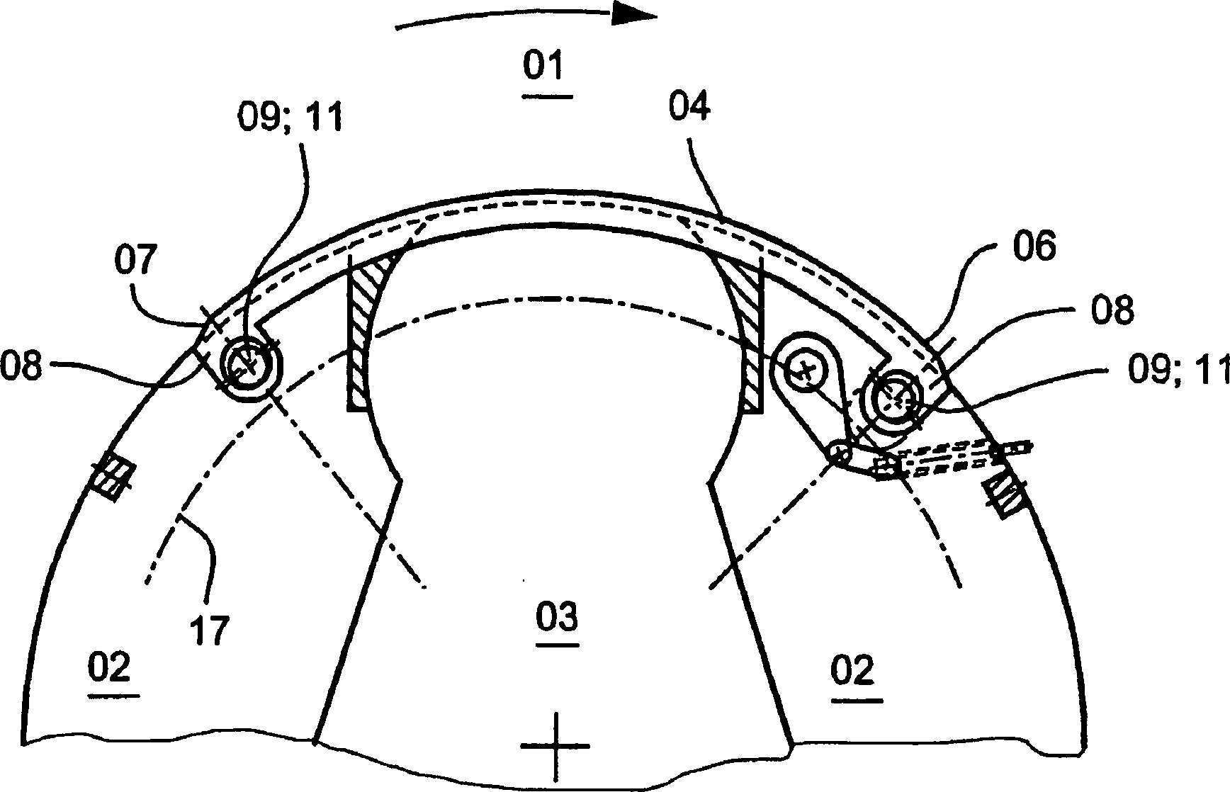
Falzapparat mit einem in einem Gestell drehbar gelagerten Zylinder (01), der an seiner Mantelfläche ein oder mehrere verstellbare Bügel (04) trägt, und mit einem Getriebe, das einerseits mit den ein oder mehreren Bügeln (04) und andererseits mit einem am Gestell fest angebrachten Antrieb zum Verstellen der Bügel (04) bei rotierendem Zylinder (01) verbunden ist, wobei das Stellgetriebe (26) eine von einem unrundem Abschnitt (28) einer Welle (27) verformte, flexible, gezahnte Hülse (29; 31) und ein mit der Hülse (29; 31) kämmendes Hohlrad (41; 42), d. h. ein „Harmonic-Drive"-Getriebe (26) umfasst, wobei das „Harmonic-Drive"-Getriebe (26) zweistufig ist, wobei der unrunde Abschnitt (28) der Welle (27) starr mit dem Antrieb verbunden ist und die flexiblen Hülsen (29; 31) starr miteinander verbunden sind und die Hohlräder (41; 42) jeweils eine an ein zum Zylinder (01) koaxiales Zahnrad (24; 38) koppelnde erste Verzahnung (36; 37) und eine mit einer der flexiblen Hülsen (29;...folding with a rotatably mounted in a frame cylinder (01), the on its lateral surface one or more adjustable brackets (04) wears, and with a gearbox, which on the one hand with the one or more brackets (04) and on the other hand with a drive fixedly mounted on the frame for adjusting the brackets (04) is connected to a rotating cylinder (01), wherein the actuating gear (26) one of a non-circular portion (28) of a shaft (27) deformed, flexible, toothed sleeve (29; 31) and one with the sleeve (29; 31) combing Ring gear (41; 42), d. H. a "harmonic drive" transmission (26), wherein the "harmonic drive" gear (26) is two-stage, wherein the non-circular portion (28) of the shaft (27) is rigidly connected to the drive and the flexible sleeves (29; 31) are rigidly connected together and the ring gears (41; 42) in each case one to a cylinder (01) coaxial gear (24, 38) coupling first toothing (36; 37) and one with one of the flexible sleeves (29; ...
Description
Die Erfindung betrifft einen Falzapparat umfangsverstellbarem Zylinder, gemäß den Merkmalen des Anspruchs 1.The Invention relates to a folder of circumferentially adjustable cylinder, according to the characteristics of claim 1.
Stand der TechnikState of the art
Ein
solcher Falzapparat ist z. B. aus
Die Stellbewegung der Spindel wird ihrerseits angetrieben mit Hilfe eines gestellfesten Planetengetriebes, das bei rotierendem Falzzylinder eine Drehung von zwei mit dem Falzzylinder koaxialen Sonnenrädern ermöglicht. Eines der Sonnenräder ist fest an die Drehung des Falzzylinders gekoppelt, eine Drehung des anderen treibt eine Kette an, die in eine Mehrzahl von Kettenrädern eingreift, die jeweils an den Spindeln montiert sind. Deren Drehung treibt eine Translation der jeweils in Gewinden geführten Spindeln an. Bei dieser Konstruktion werden die Bügel, wenn der Umfang vergrößert werden soll, in Längsrichtung gestaucht. Da die Bügel eine nichtvernachlässigbare Steifigkeit besitzen müssen, um nicht im Betrieb im Kontakt mit dem zu verarbeitenden Material verformt zu werden, ist für diese Stauchung eine erhebliche Kraft erforderlich. Eine Stellbewegung erfordert meist eine Vielzahl von Umdrehungen der Spindeln.The Actuating movement of the spindle is in turn driven by help a frame-fixed planetary gear, the rotating folding cylinder allows a rotation of two coaxial with the folding cylinder sun gears. One of the sun wheels is firmly coupled to the rotation of the folding cylinder, a rotation the other drives a chain that engages a plurality of sprockets, each mounted on the spindles. Their rotation drives a translation of each guided in threads spindles. At this Construction will be the temples, when the circumference is increased should, in the longitudinal direction compressed. As the temples one non-negligible Have to have rigidity in order not to be in contact with the material to be processed during operation to be deformed is for This compression requires a considerable force. An adjusting movement usually requires a large number of revolutions of the spindles.
Die
Die
Die
Aufgabenstellungtask
Der Erfindung liegt die Aufgabe zugrunde, einen Falzapparat mit umfangsverstellbarem Zylinder zu schaffen.Of the Invention is based on the object, a folder with circumferentially adjustable To create cylinders.
Die Aufgabe wird erfindungsgemäß durch die Merkmale des Anspruchs 1 gelöst.The Task is achieved by the features of claim 1 solved.
Die mit der Erfindung erzielbaren Vorteile liegen insbesondere darin, dass die Verwendung eines "Harmonic-Drive"-Getriebes eine sehr kompakte Bauform bei großer Belastbarkeit erlaubt.The advantages achieved by the invention are, in particular, that the use of a " harmonic drive" transmission allows a very compact design with high load capacity.
Indem zum Antreiben der Verstellung der Bügel die unrunde Welle des „Harmonic-Drive"-Getriebes mit dem Antrieb verbunden wird, können sehr niedrige Übersetzungsverhältnisse bei der Übertragung der Drehung des Antriebs auf die Bügel und damit eine sehr feinfühlige Regelung mit geringem Kraftaufwand am Antrieb erreicht werden.By doing to drive the adjustment of the strap the non-circular shaft of the "Harmonic Drive" gear with the Drive can be connected very low gear ratios in the transmission the rotation of the drive on the bracket and thus a very sensitive control be achieved with little effort on the drive.
Das "Harmonic-Drive"-Getriebe ist vorzugsweise zweistufig aufgebaut, wobei das Hohlrad einer Stufe an die Drehung des Zylinders über ein fest mit dem Zylinder verbundenes Zahnrad gekoppelt ist und das der anderen Stufe an die Bewegung der Bügel über ein um die Achse des Zylinders relativ zu diesem drehbares Zahnrad koppelt.The " harmonic drive" transmission is preferably constructed in two stages, wherein the ring gear of one stage is coupled to the rotation of the cylinder via a gear fixedly connected to the cylinder and that of the other stage to the movement of the bracket over one about the axis of the cylinder coupled relative to this rotatable gear.
Die Zahnzahlen der ersten und zweiten Verzahnungen an den Hohlrädern des „Harmonic-Drive"-Getriebes, der zum Zylinder koaxialen Zahnräder und der flexiblen Hülsen sind vorzugsweise so gewählt, dass bei stehendem Antrieb die Zahnräder mit gleicher Drehzahl rotieren. Dabei dürfen die Zahnzahlen der ersten und zweiten Verzahnungen, der zum Zylinder koaxialen Zahnräder und der flexiblen Hülsen jedoch nicht sämtlich paarweise gleich sein.The numbers of teeth of the first and second gears on the ring gears of the "harmonic drive" gear, the coaxial to the cylinder gears and the flexible sleeves are preferably chosen so that with the drive stationary, rotate the gears at the same speed. However, the numbers of teeth of the first and second gears, the gears coaxial to the cylinder and the flexible sleeves may not all be the same in pairs.
Vorzugsweise werden die Zahnzahlen der flexiblen Hülsen gleich, die der zweiten Verzahnungen der Hohlräder aber unterschiedlich gewählt. Wenn außerdem die Zahnzahlen der ersten Verzahnungen gleich sind, sollten die Zahnzahlen der koaxialen Zahnräder und der flexiblen Hülsen jeweils in einem gleichen Verhältnis stehen.Preferably The numbers of teeth of the flexible sleeves are equal, that of the second Gears of the ring gears but chosen differently. If also The numbers of teeth of the first teeth are the same, should the Numbers of teeth of the coaxial gears and the flexible sleeves each in the same ratio stand.
Alternativ können die Zahnzahlen der ersten Verzahnungen gleich und die der flexiblen Hülsen unterschiedlich gewählt werden. Wenn dann die Zahnzahlen der zweiten Verzahnungen gleich sind, dann sollten die Zahnzahlen der koaxialen Zahnräder und der zweiten Verzahnungen jeweils in einem gleichen Verhältnis stehen.alternative can the numbers of teeth of the first teeth equal and those of the flexible sleeves chosen differently become. If then the numbers of teeth of the second gears equal are, then the numbers of teeth of the coaxial gears and each of the second gears are in the same ratio.
Ausführungsbeispielembodiment
Ausführungsbeispiele der Erfindung sind in den Zeichnungen dargestellt und werden im folgenden näher beschrieben.embodiments The invention are illustrated in the drawings and are in following closer described.
Es zeigen:It demonstrate:
In
jedem Spalt
Die
Spalte
Bei
der Ausgestaltung der
Die
Die
Exzentrtzitätsvektoren
E zweier Wellen
In
Beim Übergang
von der Stellung der
Eine
dritte, vereinfachte Ausgestaltung des Falzzylinders
(Eine
solche Konstruktion kann auch den oben mit Bezug auf
Alternativ
besteht jedoch auch die Möglichkeit,
das Längsende
Umfangsänderung des Zylinders bedeutet, dass zumindest partiell eine Veränderung des Radiuses erfolgt.scope change of the cylinder means that at least partially a change of the radius.
Ein
Stellgetriebe
Wenn
der Falzzylinder ![]()
![]()
![]()
![]()
![]()
![]()
![]()
![]()
Damit
bei festgehaltener Stellwelle ![]()
![]()
Um
durch Drehen der Stellwelle
D.
h. der Mechanismus der
Im
allgemeinen sind diese zwei Bedingungen erfüllbar, denn die Zahnräder
So
ist es z. B. möglich,
die Zahnzahlen der Innen- und Außenverzahnungen der Hohlräder ![]()
![]()
![]()
![]()
Je
kleiner die Differenz der Zahnzahlen z29; z31 der flexiblen Hülsen
Alternativ
ist es z. B. möglich,
die Zahnzahlen z29; z31; z36, z37 der flexiblen Hülsen ![]()
![]()
![]()
![]()
- 0101
- Zylinder, FalzzylinderCylinder, folding cylinder
- 0202
- Segmentsegment
- 0303
- Spaltgap
- 0404
- Bügelhanger
- 0505
- 0606
- Längsendelongitudinal end
- 0707
- Längsendelongitudinal end
- 0808
- Öseeyelet
- 0909
- Exzentereccentric
- 1010
- 1111
- Wellewave
- 1212
- Lager, KugellagerCamp, ball-bearing
- 1313
- Deckscheibecover disc
- 1414
- Deckscheibecover disc
- 1515
- 1616
- Zahnrad, erstesGear, first
- 1717
- Zahnrad, zweites, ZahnkranzGear, second, sprocket
- 1818
- Spaltgap
- 1919
- Schraubescrew
- 2020
- LanglochLong hole
- 2121
- Hohlwellehollow shaft
- 2222
- Seitenplatteside plate
- 2323
- Antriebszahnraddrive gear
- 2424
- Zahnradgear
- 2525
- 2626
- Stellgetriebe, „Harmonic-Drive"-GetriebeStellgetriebe, "Harmonic Drive" gearbox
- 2727
- Welle, StellwelleWave, actuating shaft
- 2828
- Abschnitt, unrund, RotorSection, out of round, rotor
- 2929
- Hülseshell
- 3030
- Lager, KugellagerCamp, ball-bearing
- 3131
- Hülseshell
- 3232
- Verzahnung, Innenverzahnungtoothing internal gearing
- 3333
- Verzahnung, Innenverzahnungtoothing internal gearing
- 3434
- Lager, KugellagerCamp, ball-bearing
- 3535
- 3636
- Verzahnung, Außenverzahnungtoothing external teeth
- 3737
- Verzahnung, Außenverzahnungtoothing external teeth
- 3838
- Zahnradgear
- 3939
- Hülseshell
- 4040
- 4141
- Hohlradring gear
- 4242
- Hohlradring gear
- n01n01
-
Drehzahl
(
01 )Rotation speed (01 ) - n29n29
-
Drehzahl
(
29 )Rotation speed (29 ) - n38n38
-
Drehzahl
(
38 )Rotation speed (38 ) - n41n41
-
Drehzahl
(
41 )Rotation speed (41 ) - n42n42
-
Drehzahl
(
42 )Rotation speed (42 ) - z24z24
-
Zahnzahl
(
24 )Number of teeth (24 ) - z29z29
-
Zahnzahl
(
29 )Number of teeth (29 ) - z31z31
-
Zahnzahl
(
31 )Number of teeth (31 ) - z32z32
-
Zahnzahl
(
32 )Number of teeth (32 ) - z33z33
-
Zahnzahl
(
33 )Number of teeth (33 ) - z36z36
-
Zahnzahl
(
36 )Number of teeth (36 ) - z37z37
-
Zahnzahl
(
37 )Number of teeth (37 ) - z38z38
-
Zahnzahl
(
38 )Number of teeth (38 ) - AA
- Achseaxis
Claims (8)
Priority Applications (13)
| Application Number | Priority Date | Filing Date | Title |
|---|---|---|---|
| DE10148503A DE10148503C5 (en) | 2001-10-01 | 2001-10-01 | Folder with circumferentially adjustable cylinder |
| DE50210391T DE50210391D1 (en) | 2001-10-01 | 2002-09-28 | Folder with circumferentially adjustable cylinder |
| AT02776741T ATE307081T1 (en) | 2001-10-01 | 2002-09-28 | FOLDING DEVICE WITH EXTENSIVELY ADJUSTABLE CYLINDER |
| AT04101261T ATE365696T1 (en) | 2001-10-01 | 2002-09-28 | FOLDING APPARATUS WITH EXTENSIVELY ADJUSTABLE CYLINDER |
| EP04101261A EP1437318B1 (en) | 2001-10-01 | 2002-09-28 | Folding apparatus comprising a cylinder with adjustable circumference |
| EP04101264A EP1437319B1 (en) | 2001-10-01 | 2002-09-28 | Folding apparatus comprising a cylinder with adjustable circumference |
| DE50210935T DE50210935D1 (en) | 2001-10-01 | 2002-09-28 | Folder with circumferentially adjustable cylinder |
| AT04101264T ATE373619T1 (en) | 2001-10-01 | 2002-09-28 | FOLDING DEVICE WITH EXTENSIVELY ADJUSTABLE CYLINDER |
| EP02776741A EP1423324B1 (en) | 2001-10-01 | 2002-09-28 | Folding gear comprising a cylinder with adjustable circumference |
| DE50204626T DE50204626D1 (en) | 2001-10-01 | 2002-09-28 | FOLDING CAP WITH ADJUSTABLE ADJUSTABLE CYLINDER |
| US10/488,937 US7214175B2 (en) | 2001-10-01 | 2002-09-28 | Folding gear comprising a cylinder with adjustable circumference |
| AU2002339332A AU2002339332A1 (en) | 2001-10-01 | 2002-09-28 | Folding gear comprising a cylinder with adjustable circumference |
| PCT/DE2002/003684 WO2003031303A2 (en) | 2001-10-01 | 2002-09-28 | Folding gear comprising a cylinder with adjustable circumference |
Applications Claiming Priority (1)
| Application Number | Priority Date | Filing Date | Title |
|---|---|---|---|
| DE10148503A DE10148503C5 (en) | 2001-10-01 | 2001-10-01 | Folder with circumferentially adjustable cylinder |
Publications (3)
| Publication Number | Publication Date |
|---|---|
| DE10148503A1 DE10148503A1 (en) | 2003-04-24 |
| DE10148503B4 DE10148503B4 (en) | 2004-04-08 |
| DE10148503C5 true DE10148503C5 (en) | 2008-01-31 |
Family
ID=7701058
Family Applications (4)
| Application Number | Title | Priority Date | Filing Date |
|---|---|---|---|
| DE10148503A Expired - Fee Related DE10148503C5 (en) | 2001-10-01 | 2001-10-01 | Folder with circumferentially adjustable cylinder |
| DE50210935T Expired - Fee Related DE50210935D1 (en) | 2001-10-01 | 2002-09-28 | Folder with circumferentially adjustable cylinder |
| DE50210391T Expired - Fee Related DE50210391D1 (en) | 2001-10-01 | 2002-09-28 | Folder with circumferentially adjustable cylinder |
| DE50204626T Expired - Fee Related DE50204626D1 (en) | 2001-10-01 | 2002-09-28 | FOLDING CAP WITH ADJUSTABLE ADJUSTABLE CYLINDER |
Family Applications After (3)
| Application Number | Title | Priority Date | Filing Date |
|---|---|---|---|
| DE50210935T Expired - Fee Related DE50210935D1 (en) | 2001-10-01 | 2002-09-28 | Folder with circumferentially adjustable cylinder |
| DE50210391T Expired - Fee Related DE50210391D1 (en) | 2001-10-01 | 2002-09-28 | Folder with circumferentially adjustable cylinder |
| DE50204626T Expired - Fee Related DE50204626D1 (en) | 2001-10-01 | 2002-09-28 | FOLDING CAP WITH ADJUSTABLE ADJUSTABLE CYLINDER |
Country Status (6)
| Country | Link |
|---|---|
| US (1) | US7214175B2 (en) |
| EP (3) | EP1423324B1 (en) |
| AT (3) | ATE373619T1 (en) |
| AU (1) | AU2002339332A1 (en) |
| DE (4) | DE10148503C5 (en) |
| WO (1) | WO2003031303A2 (en) |
Cited By (1)
| Publication number | Priority date | Publication date | Assignee | Title |
|---|---|---|---|---|
| DE102010041457B3 (en) * | 2010-09-27 | 2011-12-01 | Koenig & Bauer Aktiengesellschaft | Adjusting arrangement of a cylinder of a folder |
Families Citing this family (10)
| Publication number | Priority date | Publication date | Assignee | Title |
|---|---|---|---|---|
| ES2357123B1 (en) * | 2009-04-03 | 2012-05-25 | Comercial Industrial Maquinaria Carton Ondulado S.L | AGAINST TROQUEL CYLINDER FOR A TROQUELING MACHINE |
| JP4951701B2 (en) * | 2010-08-11 | 2012-06-13 | 株式会社東京機械製作所 | Folding device |
| DE102011082177B3 (en) * | 2011-09-06 | 2012-03-29 | Koenig & Bauer Aktiengesellschaft | Adjusting arrangement of a cylinder of a folder and a method of adjusting a circumference of a cylinder of a folder |
| US9039855B2 (en) | 2012-03-30 | 2015-05-26 | The Procter & Gamble Company | Apparatuses and methods for making absorbent articles |
| US8440043B1 (en) | 2012-03-30 | 2013-05-14 | The Procter & Gamble Company | Absorbent article process and apparatus for intermittently deactivating elastics in elastic laminates |
| US9050213B2 (en) | 2012-03-30 | 2015-06-09 | The Procter & Gamble Company | Apparatuses and methods for making absorbent articles |
| US9028632B2 (en) | 2012-03-30 | 2015-05-12 | The Procter & Gamble Company | Apparatuses and methods for making absorbent articles |
| US20130255861A1 (en) | 2012-03-30 | 2013-10-03 | Uwe Schneider | Apparatuses and Methods for Making Absorbent Articles |
| US10766300B2 (en) | 2017-11-09 | 2020-09-08 | Michael Goren | Expandable and retractable wheel assembly |
| CN118309999B (en) * | 2024-06-11 | 2024-09-27 | 杭州和顺光影科技有限公司 | Multifunctional intelligent landscape lamp |
Citations (6)
| Publication number | Priority date | Publication date | Assignee | Title |
|---|---|---|---|---|
| DE2157615A1 (en) * | 1971-11-20 | 1973-05-24 | Frankenthal Ag Albert | DEVICE FOR FORMAT SETTING IN THE FOLDING UNIT OF ROTARY PRINTING MACHINES |
| DE2530365B2 (en) * | 1975-07-08 | 1978-09-21 | Maschinenfabrik Augsburg-Nuernberg Ag, 8900 Augsburg | Device for adjusting the diameter of a cylinder |
| DE3906975A1 (en) * | 1989-03-04 | 1990-09-06 | Frankenthal Ag Albert | FOLDING APPARATUS |
| DE4103160A1 (en) * | 1991-02-02 | 1992-08-06 | Roland Man Druckmasch | FOLDING APPARATUS WITH A DEVICE FOR ADJUSTING ADJUSTABLE ELEMENTS OF A FOLDING CYLINDER |
| DE3821442C2 (en) * | 1987-06-24 | 1993-09-09 | Mitsubishi Jukogyo K.K., Tokio/Tokyo, Jp | |
| DE19755428A1 (en) * | 1997-12-13 | 1999-06-17 | Roland Man Druckmasch | Device for adjusting the folding mechanisms on a folding cylinder of a folder |
Family Cites Families (10)
| Publication number | Priority date | Publication date | Assignee | Title |
|---|---|---|---|---|
| US3882745A (en) * | 1972-12-29 | 1975-05-13 | Koppers Co Inc | Method and apparatus for accurate die-cutting |
| US3952637A (en) * | 1975-04-14 | 1976-04-27 | Koppers Company, Inc. | Apparatus for changing the rotary position of a slotter member and for changing the relative position between fixed and movable knives on the slotter member |
| US4736660A (en) * | 1986-05-21 | 1988-04-12 | The Ward Machinery Company | Rotary die-cut apparatus and gearing arrangement therein |
| DE3726239A1 (en) * | 1987-08-07 | 1989-02-16 | Frankenthal Ag Albert | FOLDING APPARATUS |
| JP2634270B2 (en) * | 1990-01-08 | 1997-07-23 | 三菱重工業株式会社 | Folding cylinder for a rotary press |
| US5313883A (en) | 1993-04-15 | 1994-05-24 | Rockwell International Corporation | Printing press with a dynamic expansion band adjusting mechanism |
| JP2717028B2 (en) * | 1993-04-28 | 1998-02-18 | ケーニッヒ ウント バウエル−アルバート アクチエンゲゼルシャフト | Method and apparatus for correctly transferring signatures in folding apparatus |
| DE19625084C2 (en) | 1996-06-22 | 2000-12-14 | Koenig & Bauer Ag | cylinder |
| JP3056484B1 (en) | 1999-05-21 | 2000-06-26 | 株式会社東京機械製作所 | Outside diameter adjustment device for folding cylinder |
| DE10210030B4 (en) * | 2001-04-09 | 2012-04-19 | Goss International Montataire S.A. | Rotationsschwertfalzwerk |
-
2001
- 2001-10-01 DE DE10148503A patent/DE10148503C5/en not_active Expired - Fee Related
-
2002
- 2002-09-28 AU AU2002339332A patent/AU2002339332A1/en not_active Abandoned
- 2002-09-28 DE DE50210935T patent/DE50210935D1/en not_active Expired - Fee Related
- 2002-09-28 EP EP02776741A patent/EP1423324B1/en not_active Expired - Lifetime
- 2002-09-28 EP EP04101264A patent/EP1437319B1/en not_active Expired - Lifetime
- 2002-09-28 AT AT04101264T patent/ATE373619T1/en not_active IP Right Cessation
- 2002-09-28 WO PCT/DE2002/003684 patent/WO2003031303A2/en not_active Ceased
- 2002-09-28 US US10/488,937 patent/US7214175B2/en not_active Expired - Fee Related
- 2002-09-28 AT AT02776741T patent/ATE307081T1/en not_active IP Right Cessation
- 2002-09-28 AT AT04101261T patent/ATE365696T1/en not_active IP Right Cessation
- 2002-09-28 DE DE50210391T patent/DE50210391D1/en not_active Expired - Fee Related
- 2002-09-28 DE DE50204626T patent/DE50204626D1/en not_active Expired - Fee Related
- 2002-09-28 EP EP04101261A patent/EP1437318B1/en not_active Expired - Lifetime
Patent Citations (6)
| Publication number | Priority date | Publication date | Assignee | Title |
|---|---|---|---|---|
| DE2157615A1 (en) * | 1971-11-20 | 1973-05-24 | Frankenthal Ag Albert | DEVICE FOR FORMAT SETTING IN THE FOLDING UNIT OF ROTARY PRINTING MACHINES |
| DE2530365B2 (en) * | 1975-07-08 | 1978-09-21 | Maschinenfabrik Augsburg-Nuernberg Ag, 8900 Augsburg | Device for adjusting the diameter of a cylinder |
| DE3821442C2 (en) * | 1987-06-24 | 1993-09-09 | Mitsubishi Jukogyo K.K., Tokio/Tokyo, Jp | |
| DE3906975A1 (en) * | 1989-03-04 | 1990-09-06 | Frankenthal Ag Albert | FOLDING APPARATUS |
| DE4103160A1 (en) * | 1991-02-02 | 1992-08-06 | Roland Man Druckmasch | FOLDING APPARATUS WITH A DEVICE FOR ADJUSTING ADJUSTABLE ELEMENTS OF A FOLDING CYLINDER |
| DE19755428A1 (en) * | 1997-12-13 | 1999-06-17 | Roland Man Druckmasch | Device for adjusting the folding mechanisms on a folding cylinder of a folder |
Non-Patent Citations (3)
| Title |
|---|
| Katalog "Harmonic Drive Flat Type Component Sets HDUR, HDUA, HDUF Series" der Fa. Harmonic Drive, Druckdatum 2/94 * |
| offenkundige Vorbenutzung(Zeichnung"ZSB" Lager SZ F.SAMMEL- u. FALZZYLINDER" mit der Nr. B16. 20500- 0253 |
| offenkundige Vorbenutzung(Zeichnung"ZSB" Lager SZ F.SAMMEL- u. FALZZYLINDER" mit der Nr. B16. 205000253 * |
Cited By (2)
| Publication number | Priority date | Publication date | Assignee | Title |
|---|---|---|---|---|
| DE102010041457B3 (en) * | 2010-09-27 | 2011-12-01 | Koenig & Bauer Aktiengesellschaft | Adjusting arrangement of a cylinder of a folder |
| WO2012041537A1 (en) | 2010-09-27 | 2012-04-05 | Koenig & Bauer Aktiengesellschaft | Setting system of a cylinder of a folder unit |
Also Published As
| Publication number | Publication date |
|---|---|
| ATE373619T1 (en) | 2007-10-15 |
| EP1437319A2 (en) | 2004-07-14 |
| EP1437318A2 (en) | 2004-07-14 |
| EP1423324A2 (en) | 2004-06-02 |
| ATE307081T1 (en) | 2005-11-15 |
| DE10148503A1 (en) | 2003-04-24 |
| DE10148503B4 (en) | 2004-04-08 |
| EP1437319A3 (en) | 2004-07-21 |
| US7214175B2 (en) | 2007-05-08 |
| EP1437319B1 (en) | 2007-09-19 |
| WO2003031303A3 (en) | 2003-11-06 |
| EP1437318A3 (en) | 2004-07-21 |
| US20050001370A1 (en) | 2005-01-06 |
| EP1423324B1 (en) | 2005-10-19 |
| DE50204626D1 (en) | 2005-11-24 |
| DE50210935D1 (en) | 2007-10-31 |
| EP1437318B1 (en) | 2007-06-27 |
| WO2003031303B1 (en) | 2004-06-10 |
| AU2002339332A1 (en) | 2003-04-22 |
| WO2003031303A2 (en) | 2003-04-17 |
| DE50210391D1 (en) | 2007-08-09 |
| ATE365696T1 (en) | 2007-07-15 |
Similar Documents
| Publication | Publication Date | Title |
|---|---|---|
| DE102007061322B4 (en) | Eccentric gear and method for transmitting a rotational force through the eccentric gear | |
| DE102008032665B4 (en) | Device and method for changing the compression ratio of an internal combustion engine | |
| DE2652159B2 (en) | Wheel folder | |
| EP1509708A1 (en) | Transmission device comprising an eccentric power transmission axle that is disposed on the bearing axle | |
| DE10148503C5 (en) | Folder with circumferentially adjustable cylinder | |
| WO2009127183A1 (en) | Device for adjusting the eccentricity of a crank/cvt mechanism | |
| DE2060886A1 (en) | Mechanical transmission | |
| DE19625083C1 (en) | Gear for adjusting offset printing machine drive phase | |
| DE3828372A1 (en) | FOLDING APPARATUS | |
| DE4037130A1 (en) | DEVICE FOR ADJUSTING THE FOLDING FLAPS ON A FOLDING FLAP CYLINDER | |
| DE3023783C2 (en) | Device for setting the circumferential and side register of a forme cylinder of a rotary printing press | |
| EP0912345B1 (en) | Cylinder | |
| DE1960503A1 (en) | Mechanical transmission | |
| DE2253037C3 (en) | Traversing device | |
| DE10148504C1 (en) | Circumferentially adjustable cylinder for folding apparatus has sleeve face formed from segments and interposed gaps spanned by movable yokes having eccentrics engaging on each of their first and second longitudinal end | |
| EP1478589B1 (en) | Folding drum of a folding device | |
| DE3327772A1 (en) | Positive displacement machine, in particular epicyclic gear with integrated hydraulic motor | |
| DE19536061C2 (en) | Hydraulic machine | |
| DE10311393B4 (en) | Folding cylinder with adjustable elements on its lateral surface | |
| DE4244042C1 (en) | Dividing or cutting comparatively long workpieces | |
| DE102010041457B3 (en) | Adjusting arrangement of a cylinder of a folder | |
| DD153473A3 (en) | DEVICE FOR CONTROLLING THE FOLDING FLAPS OF A FOLDING CYLINDER | |
| WO2005057053A1 (en) | Gearbox | |
| DE3508186A1 (en) | DEVICE FOR GENERATING A MOTION | |
| DE3410832A1 (en) | Positive displacement machine, in particular cycloidal planetary mechanism with an integrated hydraulic motor |
Legal Events
| Date | Code | Title | Description |
|---|---|---|---|
| OP8 | Request for examination as to paragraph 44 patent law | ||
| 8363 | Opposition against the patent | ||
| 8327 | Change in the person/name/address of the patent owner |
Owner name: KOENIG & BAUER AKTIENGESELLSCHAFT, 97080 WUERZB, DE |
|
| 8366 | Restricted maintained after opposition proceedings | ||
| 8392 | Publication of changed patent specification | ||
| R119 | Application deemed withdrawn, or ip right lapsed, due to non-payment of renewal fee |
Effective date: 20120501 |