DE10019829B4 - Liquid crystal display device - Google Patents
Liquid crystal display device Download PDFInfo
- Publication number
- DE10019829B4 DE10019829B4 DE10019829A DE10019829A DE10019829B4 DE 10019829 B4 DE10019829 B4 DE 10019829B4 DE 10019829 A DE10019829 A DE 10019829A DE 10019829 A DE10019829 A DE 10019829A DE 10019829 B4 DE10019829 B4 DE 10019829B4
- Authority
- DE
- Germany
- Prior art keywords
- liquid crystal
- substrate
- alignment
- layer
- crystal molecules
- Prior art date
- Legal status (The legal status is an assumption and is not a legal conclusion. Google has not performed a legal analysis and makes no representation as to the accuracy of the status listed.)
- Expired - Lifetime
Links
Classifications
-
- G—PHYSICS
- G02—OPTICS
- G02F—OPTICAL DEVICES OR ARRANGEMENTS FOR THE CONTROL OF LIGHT BY MODIFICATION OF THE OPTICAL PROPERTIES OF THE MEDIA OF THE ELEMENTS INVOLVED THEREIN; NON-LINEAR OPTICS; FREQUENCY-CHANGING OF LIGHT; OPTICAL LOGIC ELEMENTS; OPTICAL ANALOGUE/DIGITAL CONVERTERS
- G02F1/00—Devices or arrangements for the control of the intensity, colour, phase, polarisation or direction of light arriving from an independent light source, e.g. switching, gating or modulating; Non-linear optics
- G02F1/01—Devices or arrangements for the control of the intensity, colour, phase, polarisation or direction of light arriving from an independent light source, e.g. switching, gating or modulating; Non-linear optics for the control of the intensity, phase, polarisation or colour
- G02F1/13—Devices or arrangements for the control of the intensity, colour, phase, polarisation or direction of light arriving from an independent light source, e.g. switching, gating or modulating; Non-linear optics for the control of the intensity, phase, polarisation or colour based on liquid crystals, e.g. single liquid crystal display cells
- G02F1/133—Constructional arrangements; Operation of liquid crystal cells; Circuit arrangements
- G02F1/1333—Constructional arrangements; Manufacturing methods
- G02F1/1337—Surface-induced orientation of the liquid crystal molecules, e.g. by alignment layers
- G02F1/133711—Surface-induced orientation of the liquid crystal molecules, e.g. by alignment layers by organic films, e.g. polymeric films
-
- G—PHYSICS
- G02—OPTICS
- G02F—OPTICAL DEVICES OR ARRANGEMENTS FOR THE CONTROL OF LIGHT BY MODIFICATION OF THE OPTICAL PROPERTIES OF THE MEDIA OF THE ELEMENTS INVOLVED THEREIN; NON-LINEAR OPTICS; FREQUENCY-CHANGING OF LIGHT; OPTICAL LOGIC ELEMENTS; OPTICAL ANALOGUE/DIGITAL CONVERTERS
- G02F1/00—Devices or arrangements for the control of the intensity, colour, phase, polarisation or direction of light arriving from an independent light source, e.g. switching, gating or modulating; Non-linear optics
- G02F1/01—Devices or arrangements for the control of the intensity, colour, phase, polarisation or direction of light arriving from an independent light source, e.g. switching, gating or modulating; Non-linear optics for the control of the intensity, phase, polarisation or colour
- G02F1/13—Devices or arrangements for the control of the intensity, colour, phase, polarisation or direction of light arriving from an independent light source, e.g. switching, gating or modulating; Non-linear optics for the control of the intensity, phase, polarisation or colour based on liquid crystals, e.g. single liquid crystal display cells
- G02F1/133—Constructional arrangements; Operation of liquid crystal cells; Circuit arrangements
- G02F1/1333—Constructional arrangements; Manufacturing methods
- G02F1/1337—Surface-induced orientation of the liquid crystal molecules, e.g. by alignment layers
-
- C—CHEMISTRY; METALLURGY
- C09—DYES; PAINTS; POLISHES; NATURAL RESINS; ADHESIVES; COMPOSITIONS NOT OTHERWISE PROVIDED FOR; APPLICATIONS OF MATERIALS NOT OTHERWISE PROVIDED FOR
- C09K—MATERIALS FOR MISCELLANEOUS APPLICATIONS, NOT PROVIDED FOR ELSEWHERE
- C09K2323/00—Functional layers of liquid crystal optical display excluding electroactive liquid crystal layer characterised by chemical composition
- C09K2323/02—Alignment layer characterised by chemical composition
- C09K2323/025—Polyamide
-
- C—CHEMISTRY; METALLURGY
- C09—DYES; PAINTS; POLISHES; NATURAL RESINS; ADHESIVES; COMPOSITIONS NOT OTHERWISE PROVIDED FOR; APPLICATIONS OF MATERIALS NOT OTHERWISE PROVIDED FOR
- C09K—MATERIALS FOR MISCELLANEOUS APPLICATIONS, NOT PROVIDED FOR ELSEWHERE
- C09K2323/00—Functional layers of liquid crystal optical display excluding electroactive liquid crystal layer characterised by chemical composition
- C09K2323/02—Alignment layer characterised by chemical composition
- C09K2323/027—Polyimide
-
- G—PHYSICS
- G02—OPTICS
- G02F—OPTICAL DEVICES OR ARRANGEMENTS FOR THE CONTROL OF LIGHT BY MODIFICATION OF THE OPTICAL PROPERTIES OF THE MEDIA OF THE ELEMENTS INVOLVED THEREIN; NON-LINEAR OPTICS; FREQUENCY-CHANGING OF LIGHT; OPTICAL LOGIC ELEMENTS; OPTICAL ANALOGUE/DIGITAL CONVERTERS
- G02F1/00—Devices or arrangements for the control of the intensity, colour, phase, polarisation or direction of light arriving from an independent light source, e.g. switching, gating or modulating; Non-linear optics
- G02F1/01—Devices or arrangements for the control of the intensity, colour, phase, polarisation or direction of light arriving from an independent light source, e.g. switching, gating or modulating; Non-linear optics for the control of the intensity, phase, polarisation or colour
- G02F1/13—Devices or arrangements for the control of the intensity, colour, phase, polarisation or direction of light arriving from an independent light source, e.g. switching, gating or modulating; Non-linear optics for the control of the intensity, phase, polarisation or colour based on liquid crystals, e.g. single liquid crystal display cells
- G02F1/133—Constructional arrangements; Operation of liquid crystal cells; Circuit arrangements
- G02F1/1333—Constructional arrangements; Manufacturing methods
- G02F1/1337—Surface-induced orientation of the liquid crystal molecules, e.g. by alignment layers
- G02F1/13378—Surface-induced orientation of the liquid crystal molecules, e.g. by alignment layers by treatment of the surface, e.g. embossing, rubbing or light irradiation
- G02F1/133788—Surface-induced orientation of the liquid crystal molecules, e.g. by alignment layers by treatment of the surface, e.g. embossing, rubbing or light irradiation by light irradiation, e.g. linearly polarised light photo-polymerisation
Landscapes
- Physics & Mathematics (AREA)
- Nonlinear Science (AREA)
- Spectroscopy & Molecular Physics (AREA)
- Mathematical Physics (AREA)
- Chemical & Material Sciences (AREA)
- Crystallography & Structural Chemistry (AREA)
- General Physics & Mathematics (AREA)
- Optics & Photonics (AREA)
- Liquid Crystal (AREA)
- Macromolecular Compounds Obtained By Forming Nitrogen-Containing Linkages In General (AREA)
Abstract
Flüssigkristallanzeigevorrichtung, aufweisend:
– ein erstes
und ein zweites Substrat;
– eine
erste Ausrichtungsschicht auf dem ersten Substrat, wobei die erste
Ausrichtungsschicht Polyethylenimin enthält; und
– eine Flüssigkristallschicht
zwischen dem ersten und dem zweiten Substrat,
wobei das Polyethylenimin
einen photoempfindlichen Bestandteil enthält, der ein Cinnamoyl-Derivat
enthält.A liquid crystal display device, comprising:
A first and a second substrate;
A first alignment layer on the first substrate, the first alignment layer containing polyethylenimine; and
A liquid crystal layer between the first and second substrates,
wherein the polyethyleneimine contains a photosensitive constituent containing a cinnamoyl derivative.

Description
Die Erfindung betrifft eine Flüssigkristallanzeigevorrichtung und insbesondere eine Flüssigkristallanzeigevorrichtung mit einer Ausrichtungsschicht, die photoempfindliche Materialien umfasst.The The invention relates to a liquid crystal display device and in particular, a liquid crystal display device with an alignment layer, the photosensitive materials includes.
Es ist allgemein bekannt, dass ein Flüssigkristall aus anisotropischen Molekülen besteht. Die durchschnittliche Richtung der langen Achsen der Flüssigkristallmoleküle nennt man den Direktor des Flüssigkristalls. Die Verteilung des Direktors in einem Flüssigkristall wird durch die Ankerenergie (Engl. anchoring energy) auf einem Substrat bestimmt und ist durch einen Direktor charakterisiert, der einem Minimum der Oberflächenenergie des Flüssigkristalls und der Ankerenergie entspricht. Der Direktor wird durch ein elektrisches Feld umverteilt, das während des Betriebs einer Flüssigkristallanzeigevorrichtung (LCD) erzeugt wird. Eine LCD weist zwei einander gegenüberliegende Substrate auf mit Flüssigkristall dazwischen.It It is well known that a liquid crystal of anisotropic molecules consists. The average direction of the long axes of liquid crystal molecules is called one the director of the liquid crystal. The distribution of the director in a liquid crystal is determined by the Anchoring energy (Engl anchoring energy) determined on a substrate and is characterized by a director who is a minimum the surface energy of the liquid crystal and the armature energy corresponds. The director is by an electric Redistributed during the field the operation of a liquid crystal display device (LCD) is generated. An LCD has two opposite ones Substrates on with liquid crystal between.
Um im allgemeinen eine gleichmäßige Helligkeit und ein hohes Kontrastverhältnis zu erzielen, ist es erforderlich, die Flüssigkristallmoleküle gleichmäßig in der Flüssigkristallzelle auszurichten. Einige Techniken sind vorgeschlagen worden, die Polymere verwenden, um die einzelne oder mono-domäne-homogene Ausrichtung von Flüssigkristallen zu erzielen. Insbesondere ist bekannt, dass Materialien auf Polyimid- oder Polysiloxan-Basis eine hohe Qualität und eine gute Thermostabilität aufweisen.Around in general a uniform brightness and a high contrast ratio To achieve this, it is necessary to make the liquid crystal molecules uniform in the liquid crystal cell align. Some techniques have been proposed, the polymers use the single or mono-domain homogeneous alignment of liquid crystals to achieve. In particular, it is known that materials are based on polyimide or polysiloxane-based high quality and good thermal stability.
Die üblichste Technik, die als Ausrichtungsverfahren verwendet wird, um eine mono-domäne Flüssigkristallzelle zu erhalten, umfasst das Ausbilden von Mikroriffeln auf der Oberfläche des Ausrichtungspolymers, welche das feste Verankern und das stabile Ausrichten ermöglichen. In der oben zitierten, als das Reibeverfahren bekannten Technik wird das mit einem Ausrichtungspolymer beschichtete Substrat mit einem Lappen gerieben. Das Reibeverfahren ist ein gutes Verfahren, das auf LCDs im Großmaßstab angewendet werden kann und wird daher häufig in der Industrie verwendet.The most common Technique used as an alignment method to produce a mono-domain liquid crystal cell To obtain, includes the formation of micro-corrugations on the surface of the Alignment polymer, which is the firm anchoring and stable Align. In the above-cited technique known as the rubbing method For example, the substrate coated with an alignment polymer is known rubbed a rag. The rubbing process is a good process that applied to LCDs on a large scale can and will therefore be common used in the industry.
Das Reibeverfahren bringt jedoch einige ernstzunehmende Nachteile mit sich. Da die Form der Mikroriffeln, die auf der Ausrichtungsschicht gebildet werden, von dem Reibelappen und der Reibeintensität abhängt, ist die resultierende Ausrichtung des Flüssigkristalls oft heterogen, was zu Phasenverzerrung und Lichtstreuung führt. Weiterhin verursacht eine elektrostatische Entladung (ESD), die durch Reiben der Polymeroberfläche erzeugt wird, Staubverunreinigung in einer Aktiv-Matrix-LCD-Panel, was die Herstellungsausbeute vermindert, und was das Substrat beschädigt.The However, rubbing involves some serious drawbacks yourself. Because the shape of the micro-corrugations, on the alignment layer is formed, depends on the Reibelappen and the Reibeintensität is the resulting alignment of the liquid crystal is often heterogeneous, resulting in phase distortion and light scattering. Furthermore causes a Electrostatic discharge (ESD) generated by rubbing the polymer surface Dust contamination in an active matrix LCD panel, what the Production yield is reduced and what damages the substrate.
Um
diese Probleme zu beheben, ist ein Photoausrichtungsverfahren vorgeschlagen
worden, das ein polarisiertes UV-Licht verwendet, das auf ein photoempfindliches
Polymer bestraht wird, um das Polymer zu photopolymerisieren (A.
Dyadyusha, V. Kozenkov et al., Ukr. Fiz. Zhurn., 36 (1991) 1059;
W. M. Gibbons et al., Nature, 351 (1991) 49; M. Schadt et al., Jpn.
J. Appl. Phys., 31 (1992) 2155; T. Ya. Marusii & Yu. A. Reznikov, Mol. Mat., 3 (1993)
161;
In dem Photoausrichtungsverfahren wird einer Ausrichtungsschicht durch Bestrahlen eines Substrats, das mit einem Photoausrichtungsmaterial beschichtet ist, mit einem linearpolarisierten UV-Licht eine Orientierungsrichtung verliehen. Die Photoausrichtungsschicht weist ein Polymer aus Polyvinylcinnamat (PVCN) auf und beim Bestrahlen mit linearpolarisiertem UV-Licht wird das Polymer einer Photopolymerisierung durch Quervernetzung unterworfen. Die Quervernetzung zwischen den Polymeren wird durch die Energie des UV-Lichts erzeugt.In The photo-alignment process is performed on an alignment layer Irradiating a substrate with a photo-alignment material coated, with a linear polarized UV light, an orientation direction awarded. The photo-alignment layer comprises a polymer of polyvinyl cinnamate (PVCN) on and when irradiating linear polarized UV light the polymer becomes photopolymerized by cross-linking subjected. The crosslinking between the polymers is by generates the energy of UV light.
Hinsichtlich der Richtung der Photopolymere weist die Orientierungsrichtung der Photoausrichtungsschicht eine spezifische Richtung bezüglich der Polymerisationsrichtung des linearpolarisierten UV-Lichts auf. Die Orientierungsrichtung der Photoausrichtungsschicht wird durch die Richtung der Photopolymere bestimmt. Der Vorkippwinkel der Photoausrichtungsschicht wird durch die Einfallsrichtung und durch die Bestrahlungsenergie des bestrahlten UV-Lichts bestimmt. Das heisst die Richtung des Vorkippwinkels sowie der Vorkippwinkel der Photoausrichtungsschicht werden durch die polarisierte Richtung und die Bestrahlungsenergie des bestrahlten UV-Lichts bestimmt.Regarding The direction of the photopolymers has the orientation direction of Photo alignment layer a specific direction with respect to Polymerization direction of linearly polarized UV light. The Orientation direction of the photo-alignment layer is determined by the Direction of the photopolymers determined. The pretilt angle of the photo-alignment layer is determined by the direction of incidence and by the irradiation energy of the irradiated UV light. That means the direction of the Pretilt angle and the pretilt angle of the photo alignment layer be through the polarized direction and the irradiation energy of the irradiated UV light.
Hinsichtlich der Photoausrichtung wird ein Polarisator in einem willkürlichen Winkel auf jeder Domäne der LCD rotiert. Auf das bestrahlte UV-Licht hin wird dann die Polarisationsrichtung geändert, wobei eine Mehrbereichs-LCD-Zelle mit mehreren Domänen, die in Bezug aufeinander mehrere unterschiedliche Orientierungsrichtungen haben erhalten wird.Regarding The photo orientation becomes a polarizer in an arbitrary one Angle on each domain of the LCD rotates. The polarization direction then becomes the irradiated UV light changed, wherein a multi-domain multi-domain LCD cell, the several different directions of orientation with respect to each other have been received.
Das Photoausrichtungsverfahren hat jedoch einige Nachteile. Es ist z. B. unmöglich, es in breitem Umfang anzuwenden. Vor allem führt eine niedrige Photoempfindlichkeit des Photoausrichtungsmaterials zu einer Abnahme der Anisotropie und der Thermostabilität.The However, photo-alignment method has some disadvantages. It is Z. B. impossible to apply it on a broad scale. Above all, a low photosensitivity leads of the photo-alignment material causes a decrease in anisotropy and the thermal stability.
Nach herkömmlichen Techniken dauert die Bestrahlung mit UV-Licht sehr lange, von etwa 5 bis auf 10 Minuten. Niedrige Photoempfindlichkeit und niedrige Anisotropie schwächen die Ankerenergie der endgültigen Photoausrichtungsschicht. Wird darüber hinaus der Flüssigkristall in die Flüssigkristallpanel eingefüllt, so ist erforderlich, dass das Einfüllen bei hoher Temperatur erfolgt. Eine niedrige Thermostabilität verleiht den Substraten einen Fliesseffekt, der beim Einfüllen zwischen den Substraten als ein gewelltes Muster in dem Flüssigkristall beobachtet werden kann. Ferner bleibt die Desorientierung (Engl.: disclination) aufgrund der nicht-gleichmäßigen Ausrichtung des Flüssigkristalls als ungelöstes Problem.To usual Techniques, the irradiation with UV light takes a long time, from about 5 to 10 mins. Low photosensitivity and low anisotropy weaknesses the anchor energy of the final photo-alignment layer. Will over it in addition, the liquid crystal in the liquid crystal panel filled, so it is necessary that the filling takes place at high temperature. A low thermal stability gives the substrates a creeping effect when filling between the substrates as a wavy pattern in the liquid crystal can be observed. Furthermore, the disorientation (Engl .: disclination) due to non-uniform alignment of the liquid crystal as unresolved Problem.
In
Aus
Folglich ist die Erfindung auf eine LCD gerichtet, die ein oder mehrere der Probleme, die sich aus den Einschränkungen und Nachteilen des Standes der Technik ergeben, im wesentlichen behebt.consequently For example, the invention is directed to an LCD comprising one or more of the Problems arising from the limitations and disadvantages of State of the art revealed, essentially fixes.
Ein Ziel der Erfindung ist das Schaffen einer Flüssigkristallanzeigevorrichtung, die eine Ausrichtungsschicht aufweist, die Materialien umfasst, die gute Thermostabilität und Photoempfindlichkeit aufweisen.One The object of the invention is to provide a liquid crystal display device, having an alignment layer comprising materials, the good thermostability and photosensitivity.
Zusätzliche Merkmale und Vorteile der Erfindung werden in der nachfolgenden Beschreibung erläutert werden und werden sich teilweise aus der Beschreibung ergeben oder können durch Ausführen der Erfindung gelernt werden. Die Ziele und andere Vorteile der Erfindung werden durch die Struktur, die in der Beschreibung und Ansprüche hiervon insbesondere hervorgehoben wird, realisiert und erreicht werden.additional Features and advantages of the invention will become apparent in the following Description will be explained and will partly result from the description or may by To run of the invention. The goals and other benefits of Invention are characterized by the structure that in the description and claims This is particularly emphasized, realized and achieved become.
Um diese und andere Vorteile zu erzielen, und gemäß dem Zweck der Erfindung wie sie hier ausgeführt und beschrieben wird, weist die Flüssigkristallanzeigevorrichtung der Erfindung auf: ein erstes und zweites Substrat; eine erste Ausrichtungsschicht auf dem ersten Substrat, wobei die erste Ausrichtungsschicht Polyethylenimin enthält; und eine Flüssigkristallschicht zwischen dem ersten und dem zweiten Substrat, wobei das Polyethylenimin photoempfindliche Bestandteile enthält, die ein Material enthalten, das aus Cinnamoyl-Derivaten besteht.Around to achieve these and other advantages, and in accordance with the purpose of the invention they executed here and Fig. 12, shows the liquid crystal display device of the invention: a first and a second substrate; a first alignment layer on the first substrate, wherein the first alignment layer is polyethylenimine contains; and a liquid crystal layer between the first and second substrates, wherein the polyethyleneimine contains photosensitive constituents containing a material which consists of cinnamoyl derivatives.
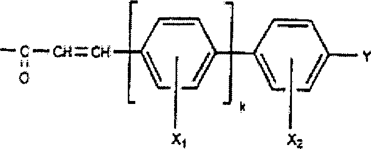
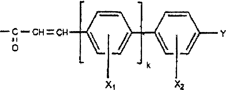
Das Cinnamoyl-Derivat enthält mindestens ein Mitglied, das aus der Gruppe ausgewählt ist, die aus Wasserstoff, Fluor, Chlor, Cyano, NO2, CH3, OCH3, CF3, OCF3, CnH2n+1-xFx (n = 1–10, x = 0–2n+1), OCnH2n+1-xFx (n = 1–10, x = 0–2n + 1), C6H5,Fx (n = 1–10, x = 0–5), C6H4OCnH2n+1-xFx (n = 1–10, x = 0–2n + 1) besteht.The cinnamoyl derivative contains at least one member selected from the group consisting of hydrogen, fluorine, chlorine, cyano, NO 2 , CH 3 , OCH 3 , CF 3 , OCF 3 , C n H 2n + 1-x F x (n = 1-10, x = 0-2n + 1), OC n H 2n + 1-x F x (n = 1-10, x = 0-2n + 1), C 6 H 5 , F x (n = 1-10, x = 0-5), C 6 H 4 OC n H 2n + 1-x F x (n = 1-10, x = 0-2n + 1).
Das
Polyethylenimin ist: 
Des
weiteren ist das Polyethylenimin: 

Bevorzugt weist die Flüssigkristallanzeigevorrichtung der Erfindung eine zweite Ausrichtungsschicht auf dem zweiten Substrat auf. Die zweite Ausrichtungsschicht enthält ein Material, das aus der Gruppe ausgewählt ist, die aus einem Pyranosepolymer, einem Furanosepolymer, Polyvinylcinnamat, Polysiloxancinnamat, Polyvinylalkohol, Polyamid, Polyamid, Polyamidsäure und Siliziumdioxid besteht.Prefers includes the liquid crystal display device of the invention, a second alignment layer on the second substrate on. The second alignment layer includes a material made from the Group selected consisting of a pyranose polymer, a furanose polymer, polyvinyl cinnamate, Polysiloxancinnamate, polyvinyl alcohol, polyamide, polyamide, polyamic acid and Silica exists.
Die erste und die zweite Ausrichtungsschicht ist in mindestens zwei Domänen zum unterschiedlichen Ansteuern der Flüssigkristallmoleküle in der Flüssigkristallschicht in jeder Domäne unterteilt. Ebenso beschrieben ist, dass die erste oder die zweite Ausrichtungsschicht in mindestens zwei Abschnitten zum unterschiedlichen Ausrichten der Flüssigkristallmoleküle in der Flüssigkristallschicht in jedem Abschnitt unterteilt ist.The the first and second alignment layers are in at least two domains for differently driving the liquid crystal molecules in the liquid crystal layer in every domain divided. Also described is that the first or the second Alignment layer in at least two sections to different Aligning the Liquid Crystal Molecules in the liquid crystal layer is divided into each section.
Die Flüssigkristallschicht enthält Flüssigkristallmoleküle, die eine positive oder eine negative dielektrische Anisotropie aufweisen.The liquid crystal layer contains Liquid crystal molecules, the have a positive or a negative dielectric anisotropy.
Es ist anzumerken, dass sowohl die obenstehende allgemeine Beschreibung als auch die nachfolgende detaillierte Beschreibung als beispielhaft und erläuternd zu verstehen sind, und diese sollen die Erfindung wie beansprucht weiter erläutern.It It should be noted that both the general description above as well as the following detailed description as an example and explanatory are to be understood, and these are intended to claim the invention as claimed further explain.
Die zugehörigen Zeichnungen, die zur Ermöglichung eines besseren Verständnisses der Erfindung beigefügt sind, und die einen Teil der Beschreibung ausmachend in diese mit aufgenommen sind, zeigen Ausführungsformen der Erfindung und, zusammen mit der Beschreibung, dienen der Erläuterung der Erfindung.The associated Drawings that allow for a better understanding attached to the invention are, and that part of the description making in this with are included, show embodiments of the invention and, together with the description, serve to explain the invention.
In den Zeichnungen zeigt:In the drawings shows:
Bevorzugte Ausführungsformen der Erfindung werden nachfolgend detailliert erläutert.preferred embodiments The invention will be explained in detail below.
Um die Empfindlichkeit einer Fotoausrichtungsschicht für eine Flüssigkristallvorrichtung zu verbessern, und um eine thermostabile Verankerung des Flüssigkristalls zu erhalten, wird gemäß der Ausführungsform der Erfindung als Fotoausrichtungsmaterial ein Polyethylencinnamat (PECN) verwendet. Einige unterschiedliche Formen des PECNs, die für die Verwendung in der Erfindung geeignet sind, werden als Derivate eines Polyethylenimins und eines Cinnamoylchlorids, die unterschiedliche Substitutionsverhältnisse haben, erhalten.Around the sensitivity of a photo-alignment layer for a liquid crystal device to improve, and to a thermostable anchoring of the liquid crystal is obtained according to the embodiment the invention as a photo-alignment material a polyethylene cinnamate (PECN) used. Several different forms of PECNs that for the Use in the invention are as derivatives of a Polyethyleneimine and a cinnamoyl chloride, the different substitution ratios have received.
Eine Zimtsäure wird zunächst durch Umsetzen eines Benzaldehyds mit Malonsäure in Pyridin und Piperidin hergestellt. Die Zimtsäure wird dann mit Thionyichlorid umgesetzt, um ein Cinnamoylchlorid-Derivat herzustellen. Schließlich wird das PECN durch Umsetzen von PECN mit dem Cinnamoylchlorid-Derivat in einem inerten Lösungsmittel (wie beispielsweise Chloroform, Nitrobenzol, Chlorobenzol und dergleichen) synthetisiert. Der Reaktionsansatz wird mit Methanol verdünnt, wird gefiltert, wird unter Vakuum getrocknet, und wird durch eine Schwenkkraftmühle gefräst, wodurch das PECN erhalten wird.A cinnamic acid will be first by reacting a benzaldehyde with malonic acid in pyridine and piperidine produced. The cinnamic acid is then reacted with thionyl chloride to produce a cinnamoyl chloride derivative. After all becomes the PECN by reacting PECN with the cinnamoyl chloride derivative in an inert solvent (such as chloroform, nitrobenzene, chlorobenzene and the like) synthesized. The reaction mixture is diluted with methanol filtered, is dried under vacuum, and is milled by a rotary power mill, thereby the PECN is obtained.
Das PECN schafft eine gute homogene oder homöotrope Ausrichtung in der Flüssigkristallausrichtung, insbesondere zeigt die homöotrope Ausrichtung beim Anlegen der Spannung darauf eine Anisotropie in dem Azimuthalwinkel.The PECN provides a good homogeneous or homeotropic alignment in the liquid crystal orientation, In particular, the homeotropic shows Orientation when applying the voltage to anisotropy in the Azimuthal angle.
Ein Verfahren zum Bilden einer Ausrichtungsschicht mit PECN gemäß einer Ausführungsform der Erfindung weist die folgenden Schritte auf.One A method of forming an alignment layer with PECN according to embodiment The invention comprises the following steps.
Ein Glassubstrat wird unter Rotieren beschichtet (Engl.: spincoating), wird getrocknet und mit der PECN-Lösung wärmebehandelt, um eine Ausrichtungsschicht zu bilden. Die Ausrichtungsschicht wird mit polarisiertem UV-Licht bestrahlt, um eine Anisotropie in dem PECN zu induzieren. Die Glassubstrate, die wie oben beschrieben erhalten werden, werden derart laminiert, da sie einander gegenüberliegen, und die Flüssigkristallzelle wird dann durch Einfüllen des Flüssigkristalls in einer nematischen oder isotropen Phase hergestellt.One Glass substrate is coated under rotation (Engl .: spincoating), is dried and heat treated with the PECN solution to form an alignment layer to build. The alignment layer is made with polarized UV light irradiated to induce anisotropy in the PECN. The glass substrates, obtained as described above are laminated in such a way that because they are opposite each other, and the liquid crystal cell is then filled by filling of the liquid crystal produced in a nematic or isotropic phase.
[Bilden einer homotropen Ausrichtung in einer Flüssigkristallanzeigevorrichtung in homotropen Modus][Forming a homotropic alignment in a liquid crystal display device in homotropic mode]
1. Bilden einer PECN-Ausrichtungsschicht auf Substrat1. Forming a PECN alignment layer on substrate
Polyethylenimin-4-pentoxycinnamat wird in Dichlorethan zu 50 g/l gelöst, die Lösung wird auf ein Glassubstrat getropft und wird anschließend unter Rotieren beschichtet (Engl.: spin-coated) während bei einer Rotationsgeschwindigkeit von 2000 UpM für 10–30 Sekunden zentrifugiert wird. Eine Schicht mit einer Dicke von etwa 0,1 μm wird erhalten, und die hergestellte Schicht wird unverzüglich bei 100°C für eine Stunde getrocknet, um das Lösungsmittel auf dem Substrat zu entfernen.Polyethyleneimine-4-pentoxycinnamat is dissolved in dichloroethane to 50 g / l, the solution is applied to a glass substrate dripped and then spin-coated while rotating at a speed of rotation from 2000 rpm for 10-30 Centrifuged for a few seconds. A layer with a thickness of about 0.1 μm received, and the produced layer is added immediately 100 ° C for one hour dried to the solvent to remove on the substrate.
2. Behandlung der Photoausrichtung2. Treatment of photo orientation
Die PECN-Schicht auf dem Substrat wird mit polarisiertem UV-Licht von einer Hg-Lampe bei 250–500 W bestrahlt. Linear polarisiertes Licht wird durch Durchscheinenlassen des Lichts durch eine Quarzlinse und ein Glan-Thomson Prisma erhalten. Die Intensität (I0) des Lichtes beträgt 10 mW/cm2 auf der Ausrichtungsschicht.The PECN layer on the substrate is irradiated with polarized UV light from a Hg lamp at 250-500W. Linearly polarized light is obtained by passing the light through a quartz lens and a Glan-Thomson prism. The intensity (I 0 ) of the light is 10 mW / cm 2 on the alignment layer.
Die Bestrahlung mit Licht wird zweimal durchgeführt. Bei der ersten Bestrahlung wird das UV-Licht senkrecht auf das Substrat bestrahlt und die Polarisationsrichtung des UV-Lichts ist senkrecht zu einer Seite des Substrats. Die Bestrahlungszeit beträgt 5–20 Min. Bei der zweiten Bestrahlung wird das UV-Licht bei einer Neigung von 45°C auf das Substrat bestrahlt und die Polarisationsrichtung des UV-Lichts wird bei der ersten Bestrahlung entgegen der Polarisationsrichtung des UV-Lichts rotiert. Die Bestrahlungszeit beträgt 10–30 Sekunden.The Irradiation with light is performed twice. At the first irradiation The UV light is irradiated perpendicular to the substrate and the polarization direction of UV light is perpendicular to one side of the substrate. The irradiation time is 5-20 min. At the second irradiation, the UV light becomes at a tilt from 45 ° C irradiated to the substrate and the polarization direction of the UV light becomes opposite to the polarization direction at the first irradiation of UV light. The irradiation time is 10-30 seconds.
3. Laminieren der Zelle und Einfüllen des Flüssigkristalls3. Laminate the cell and fill in the liquid crystal
Die zwei aus dem obigen Verfahren erhaltenen Substrate werden bei Beibehaltung des Zellenspalts davon mit den Abstandshaltern von 5–6 μm Größe laminiert. Ein Flüssigkristall, der eine negative dielektrische Anisotropie aufweist, wird durch den Kapillardruck bei einer Temperatur oberhalb TNI (nematische isotrope Phase-Übergangs-Temperatur: Aufhellpunkt (Engl.: clearing point)) darin eingefüllt. Danach, erreicht der Zustand in der Zelle innerhalb 10 Min Gleichgewicht. Demzufolge weist die Flüssigkristallzelle eine hervorragende homöotrope Ausrichtung auf, und gibt es einen Bereich, der nicht photoausrichtungsbehandelt wird, so wird die homöotrope Ausrichtung auch in dem Bereich beobachtet.The two substrates obtained from the above method are laminated with the spacers of 5-6 μm in size while maintaining the cell gap thereof. A liquid crystal having a negative dielectric anisotropy is filled therein by the capillary pressure at a temperature above T NI (nematic isotropic phase transition temperature: clearing point). After that, the condition in the cell reaches equilibrium within 10 min. Accordingly, the liquid crystal cell has excellent homeotropic orientation, and if there is a region which is not photo-aligned, the homeotropic alignment is also observed in the region.
Die PECN-Schicht weist eine Anisotropie auf der Oberfläche davon auf, die beim Anlegen der Spannung darauf beobachtet werden konnte. Das heißt, wenn das elektrische Feld erzeugt wird, werden die Flüssigkristalldirektoren gleichmäßig in einer der Richtung der geneigten Bestrahlung entgegengesetzten Richtung geneigt, und Flüssigkristalldirektoren werden durch das elektrische Feld in eine Richtung angeordnet, die senkrecht zu der Polarisationsrichtung des Bestrahlungslichtes ist.The PECN layer has anisotropy on the surface thereof on, which could be observed when applying the voltage to it. This means, When the electric field is generated, the liquid crystal directors become evenly in one tilted in the opposite direction to the direction of the inclined irradiation, and liquid crystal directors are arranged by the electric field in a direction perpendicular to the polarization direction of the irradiation light.
Daher schafft das Material der Ausrichtungsschicht der vorliegenden Erfindung eine gleichmäßige Ausrichtung, und die Richtung des einfallenden UV-Lichtes bestimmt die Neigungsrichtung der Direktoren. Nach dem obigen kann die Mehrdomäne-Struktur, die die Bereiche aufweist, in denen die Ausrichtungsorientierungen voneinander verschieden sind, gebildet werden, so daß man die Flüssigkristallanzeigevorrichtung mit den Eigenschaften eines hohen Kontrastverhältnisses und eines breiten Sichtwinkels herstellen kann.Therefore provides the material of the alignment layer of the present invention a uniform alignment, and the direction of the incident UV light determines the direction of inclination the directors. After the above, the multi-domain structure containing the areas in which the orientation orientations are different from each other are, be formed, so that one the liquid crystal display device with the properties of a high contrast ratio and a wide View angle can produce.
[Bilden einer homogenen Ausrichtung in einer Flüssigkristalanzeigevorrichtung in verdrehtem nematischen Modus][Forming a homogeneous alignment in a liquid crystal display device in twisted nematic mode]
1. Bilden der PECN-Ausrichtungsschicht auf dem Substrat1. Forming the PECN alignment layer on the substrate
Polyethylenimin-4-Fluorocinnamat wird in Dichlorethan zu 50 g/l gelöst, die Lösung wird auf ein Glassubstrat getropft und wird anschließend unter Rotieren beschichtet (Engl.: sein-coated) während bei einer Rotationsgeschwindigkeit von 2000 UpM für 10–30 Sekunden zentrifugiert wird. Dabei erhält man eine Schicht mit einer Dicke von etwa 0,1 μm und die hergestellte Schicht wird unverzüglich bei 100°C für eine Stunde getrocknet, um das Lösungsmittel auf dem Substrat zu entfernen.Polyethyleneimine-4-Fluorocinnamat is dissolved in dichloroethane to 50 g / l, the solution is applied to a glass substrate dripped and then while rotating coated (Engl .: sein-coated) while at centrifuged at a speed of 2000 rpm for 10-30 seconds becomes. It receives one layer with a thickness of about 0.1 microns and the layer produced will be instant at 100 ° C for one Hour dried to the solvent to remove on the substrate.
2. Behandlung der Fotoausrichtung2. Treatment of the photo orientation
Die PECN-Schicht auf dem Substrat wird mit polarisiertem UV-Licht von einer Hg-Lampe bei 250–500 W bestrahlt. Linear polarisiertes Licht wird dadurch erhalten, dass man das Licht durch eine Quarzlinse und ein Glan-Thomson Prisma hindurchscheinen lässt. Die Intensität (I0) des Lichtes beträgt 10 mW/cm2 der Ausrichtungsschicht. Bei der Bestrahlung des Lichtes wird das UV-Licht senkrecht zum Substrat bestrahlt und die Polarisationsrichtung (EUV) des UV-Lichts ist senkrecht zu einer Seite des Substrats. Die Bestrahlungszeit beträgt 5–15 Min.The PECN layer on the substrate is irradiated with polarized UV light from a Hg lamp at 250-500W. Linearly polarized light is obtained by passing the light through a quartz lens and a Glan-Thomson prism. The intensity (I 0 ) of the light is 10 mW / cm 2 of the alignment layer. Upon irradiation of the light, the UV light is irradiated perpendicular to the substrate and the polarization direction (E UV ) of the UV light is perpendicular to one side of the substrate. The irradiation time is 5-15 min.
3. Laminieren der Zelle und Einfüllen des Flüssigkristalls Eine Zelle setzt sich aus dem Substrat, das aus dem oben beschriebenen Verfahren erhalten wird, und dem anderen Substrat mit einer durch Reiben behandelten Polyimidschicht zusammen.Third Lamination of the cell and filling of the liquid crystal A cell is made up of the substrate that is the one described above Process is obtained, and the other substrate with a through Rub treated polyimide layer together.
Die Reibungsrichtung der Polyimidschicht und die Ausrichtungsorientierung der Flüssigkristalldirektoren auf der Oberfläche davon sind parallel zu der langen Seite des Substrats. Der Vorkippwinkel (θPI) der Oberfläche des Substrats beträgt ungefähr 1°, was den Flüssigkristalldirektoren eine starke Ankerenergie verleiht.The rubbing direction of the polyimide layer and the alignment orientation of the liquid crystal directors on the surface thereof are parallel to the long side of the substrate. The pretilt angle (θ PI ) of the surface of the substrate is about 1 °, which gives the liquid crystal directors a strong anchor energy.
Die zwei obigen Substrate werden unter Beibehaltung des Zellspalts davon mittels der Abstandshalter von 5–6 μm Größe laminiert. Ein Flüssigkristall, der eine positive dielektrische Anisotropie aufweist (LC ZLI 4801), wird bei einer Temperatur von 90°C in isotroper Phase darin eingefüllt.The two above substrates are preserved while maintaining the cell gap thereof laminated by means of spacers of 5-6 μm size. A liquid crystal, which has a positive dielectric anisotropy (LC ZLI 4801), is at a temperature of 90 ° C filled in isotropic phase therein.
Die PECN-Schicht in der Flüssigkristallzelle schafft eine gute homogene Ausrichtung. Verläuft die Polarisationsrichtung des einfallenden Lichtes parallel zu der langen Seite des Substrats, so kann eine gute, um 90° verdrehte Struktur erhalten werden. Verläuft andererseits die Polarisationsrichtung des einfallenden Lichtes senkrecht zu der langen Seite des Substrats, so weist es eine homogene Struktur auf. Die obige Tatsache rührt daher, dass die Ausrichtungsachse senkrecht zu der Polarisationsrichtung des W-Lichtes liegt, und das Ausrichtungsmaterial verleiht dem Flüssigkristall eine starke Ankerenergie.The PECN layer in the liquid crystal cell creates a good homogeneous alignment. Runs the polarization direction the incident light parallel to the long side of the substrate, so can a good 90 ° twisted Structure can be obtained. runs on the other hand, the polarization direction of the incident light perpendicular to the long side of the substrate, so it has a homogeneous Structure on. The above fact is due to the fact that the alignment axis is perpendicular to the polarization direction of the W light, and the alignment material gives the liquid crystal strong anchor energy.
Das oben Beschriebene zeigt, dass das Ausrichtungsmaterial bei allen Fotoausrichtungsbehandlungen angewendet werden kann. Z. B. kann man die Ausrichtungsbehandlung des PECNs nicht nur durch einmalige Bestrahlung mit polarisiertem Licht, sondern auch durch einmalige, geneigte Bestrahlung mit nicht polarisiertem Licht durchführen. Des weiteren induziert die geneigte Bestrahlung das geneigte Ausrichten des Flüssigkristalls und die Änderung der Bestrahlungszeit, der Wärmebehandlung, der Bedienungsparameter der Spin-Beschichtung, der Ankerenergie und des Vorkippwinkels.The above described shows that the alignment material at all Photo alignment treatments can be applied. For example, can Not only the one-time registration treatment of the PECN Irradiation with polarized light, but also by unique, perform inclined irradiation with unpolarized light. Of Further, the inclined irradiation induces the inclined alignment of the liquid crystal and the change the irradiation time, the heat treatment, the operating parameter of the spin coating, the armature energy and the pretilt angle.
Bevorzugte Ausführungsformen der Erfindung werden jetzt detaillierter erläutert. Es ist anzumerken, dass diese Beispiele lediglich erläuternd sein sollen, und dass die Erfindung nicht auf die Bedingungen, Materialien oder die Vorrichtungen, die darin genannt sind, beschränkt ist.preferred embodiments The invention will now be explained in more detail. It should be noted that these examples are merely illustrative should be, and that the invention does not affect the conditions, materials or the devices mentioned therein is limited.
Beispiel 1example 1
Synthese der 4-FluorzimtsäureSynthesis of 4-fluorocinnamic acid
Eine Mischung von 0,1 mol 4-Fluorbenzaldehyd, 0,15 mol Malonsäure und 0,1 ml Piperidin in 30 ml Pyridin wird für 10 Stunden gesiedet, wird abgekühlt und wird mit 150 ml 10% HCl behandelt. Der Niederschlag wird gefiltert und wird mit Ethanol kristallisiert. Die Ausbeute der 4-Fluorzimtsäure beträgt 68% und der Schmelzpunkt beträgt 211°C.A Mixture of 0.1 mol of 4-fluorobenzaldehyde, 0.15 mol of malonic acid and 0.1 ml of piperidine in 30 ml of pyridine is boiled for 10 hours chilled and is treated with 150 ml of 10% HCl. The precipitate is filtered and is crystallized with ethanol. The yield of 4-fluorocinnamic acid is 68% and the melting point is 211 ° C.
Die
folgenden Verbindungen werden in einer ähnlichen Weise synthetisiert:
2-Fluorzimtsäure;
3-Fluorzimtsäure;
3-Chlorzimtsäure;
4-Chlorzimtsäure;
2-Methylzimtsäure;
4-Phenylzimtsäure;
4-Methoxyzimtsäure;
4-Pentoxyzimtsäure;
4-Heptyloxyzimtsäure;
4-Nonyloxyzimtsäure;
4-(4-Pentoxyphenyl)Zimtsäure;
4-Trifluormethoxyzimtsäure;
4-Trifluormethylzimtsäure;
4-Pentylzimtsäure; und
4-Methoxy-3-fluorzimtsäure.The following compounds are synthesized in a similar manner:
2-fluorocinnamic acid;
3-fluorocinnamic acid;
3-chlorocinnamic acid;
4-chlorocinnamic acid;
2-methylcinnamic acid;
4-phenylcinnamic acid;
4-methoxycinnamic acid;
4-Pentoxyzimtsäure;
4-Heptyloxyzimtsäure;
4-Nonyloxyzimtsäure;
4- (4-pentoxyphenyl) cinnamic acid;
4-Trifluormethoxyzimtsäure;
4-trifluoromethylcinnamic acid;
4-Pentylzimtsäure; and
4-methoxy-3-fluorocinnamic acid.
Beispiel 2Example 2
Synthese von PolyethylenimincinnamatSynthesis of polyethyleneimine amine
Eine Mischung von 0,05 mol Cinnamoylchlorid (hergestellt ausgehend von einer Zimtsäure, die im Beispiel 1 hergestellt ist, einem Überschuß von Thionylchlorid und katalytischen Mengen von Dimethylformamid), 0,04 mol Polyethylenimin und 0,06 mol Pyridin in 40 ml Chloroform wird 24 Stunden bei 20°C erwärmt, wird abgekühlt und wird mit Methanol verdünnt. Das Reaktionsprodukt wird filtriert, wird mit Methanol und Wasser gewaschen, wird unter Vakuum getrocknet und wird anschließend durch eine Schwenkkraftmühle gefräst. Die Ausbeute des Polyethylenimincinnamats beträgt ungefähr 60%–90%. Dünnschichtchromatographie (TLC) ergibt, das fast keine Zimtsäure in den Reaktionsprodukten vorhanden ist.A Mixture of 0.05 mol of cinnamoyl chloride (prepared starting from a cinnamic acid, which is prepared in Example 1, an excess of thionyl chloride and catalytic Amounts of dimethylformamide), 0.04 moles of polyethyleneimine and 0.06 mol of pyridine in 40 ml of chloroform is heated for 24 hours at 20 ° C, is cooled and is diluted with methanol. The reaction product is filtered, washed with methanol and water, is dried under vacuum and is then milled by a rotary power mill. The yield of the polyethyleneimine amine is about 60% -90%. Thin Layer Chromatography (TLC) that gives almost no cinnamic acid is present in the reaction products.
Beispiel 3Example 3
Synthese von hydroxyethyliertem PolyethylenimincinnamatSynthesis of hydroxyethylated polyethyleneimine amine
Eine Mischung von 0,05 mol Cinnamoylchlorid (herstellt ausgehend von einer Zimtsäure, die in Beispiel 1 hergestellt ist, einem Überschuß von Thionylchlorid und katalytischen Mengen von Dimethylformamid), 0,01 mol hydroxyethyliertem Polyethylenimin und 0,06 mol Pyridin in 20 ml Nitrobenzol wird für 24 Stunden bei 80°C erwärmt, und wird mit Methanol verdünnt. Das Reaktionsprodukt wird filtriert, wird mit Methanol und Wasser gewaschen, wird unter Vakuum getrocknet und wird anschließend durch eine Schwenkkraftmühle gefräst. Die Ausbeute des hydroxylethylierten Polyethylenimincinnamats beträgt ungefähr 60%–90%. Dünnschichtchromatographie (TLC) ergibt, das fast keine Zimtsäure in den Reaktionsprodukten vorhanden ist.A Mixture of 0.05 mol of cinnamoyl chloride (prepared starting from a cinnamic acid, which is prepared in Example 1, an excess of thionyl chloride and catalytic Amounts of dimethylformamide), 0.01 mol of hydroxyethylated polyethyleneimine and 0.06 mol of pyridine in 20 ml of nitrobenzene is heated at 80 ° C for 24 hours, and is diluted with methanol. The reaction product is filtered, washed with methanol and water washed, is dried under vacuum and is then passed through a rotary power mill milled. The Yield of the hydroxylated polyethyleneimine amine is about 60% -90%. TLC (TLC) shows that almost no cinnamic acid in the reaction products is available.
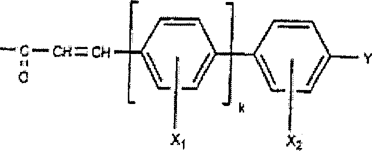
Der
Mechanismus gemäß einer
Ausführungsform
der vorliegenden Erfindung ist wie folgt: 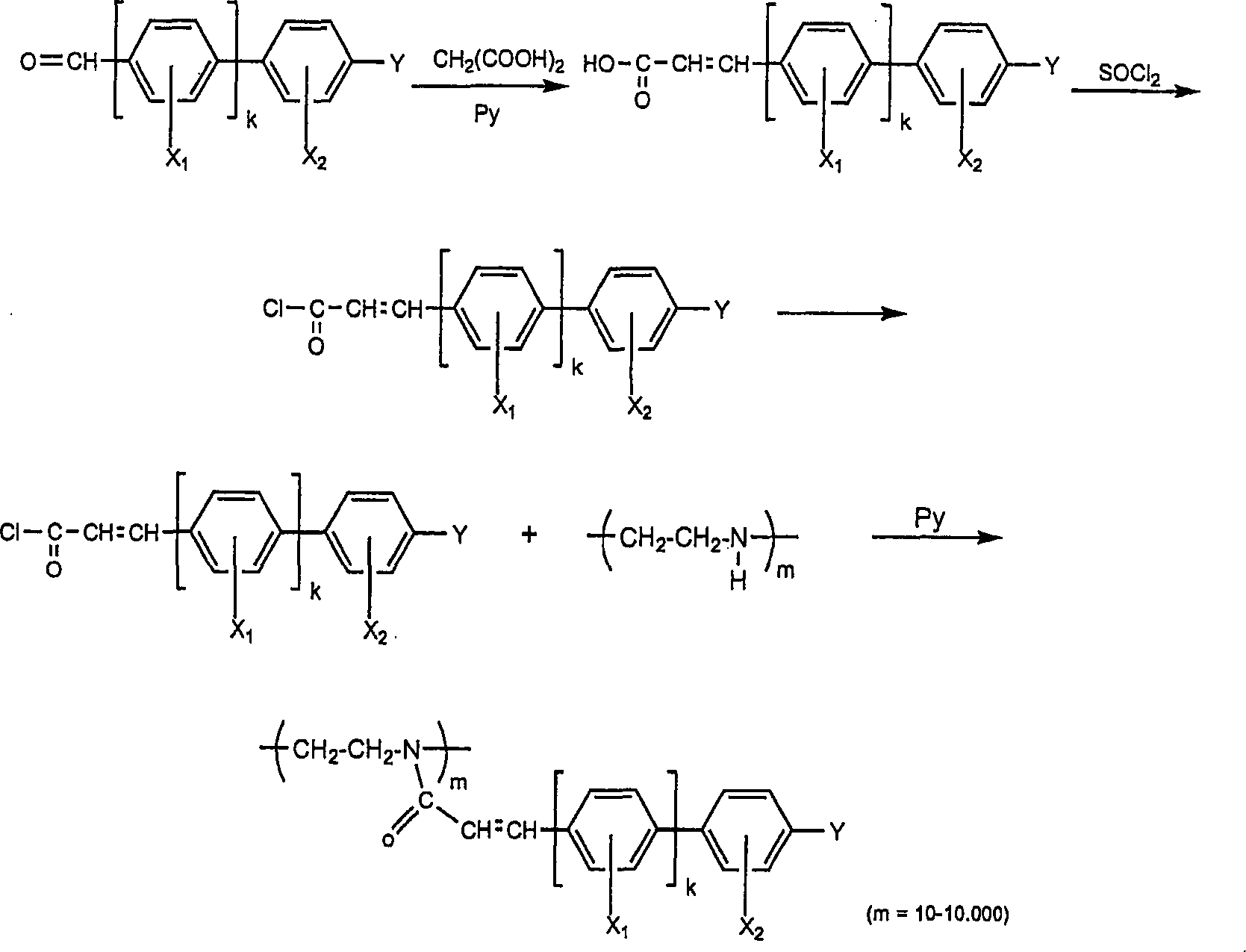
k = 0–1
Y ist Wasserstoff,
Fluor, Chlor, CN, CF3, OCF3,
CnH2n+1, OCnH2n+1 (n = 1–10)The mechanism according to an embodiment of the present invention is as follows:
k = 0-1
Y is hydrogen, fluorine, chlorine, CN, CF 3 , OCF 3 , C n H 2n + 1 , OC n H 2n + 1 (n = 1-10)
Ferner umfassen Cinnamoyl-Derivate Wasserstoff, Fluor, Chlor, CN, NO2, CH3, OCH3, CF3, OCF3, CnH2+1-xFx (n = 1–10, x = 0–2n + 1) OCnH2n+1-xFx (n = 1–10, x = 0-2n+1), C6H5-xFx (n = 1–10, x = 0–5), C6H4OCnH2n+1-xFx (n = 1–10, x = 0–2n + 1).Further, cinnamoyl derivatives include hydrogen, fluorine, chlorine, CN, NO 2 , CH 3 , OCH 3 , CF 3 , OCF 3 , C n H 2 + 1-x F x (n = 1-10, x = 0-2n + 1) OC n H 2n + 1-x F x (n = 1-10, x = 0-2n + 1), C 6 H 5 -x F x (n = 1-10, x = 0-5) , C 6 H 4 OC n H 2n + 1-x F x (n = 1-10, x = 0-2n + 1).
Weiterhin
ist es möglich,
dass das Polyethylenimin 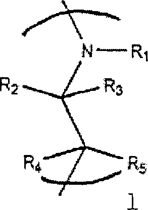
Ein Abstandshalter ist zwischen dem Polyethylenimin und dem photoempfindlichen Bestandteil vorgesehen, und ist aus der Gruppe ausgewählt, die aus (CH2)mO, (CH2)mN, (CH2)m (m = 0–10) besteht.A spacer is provided between the polyethyleneimine and the photosensitive component, and is selected from the group consisting of (CH 2 ) m O, (CH 2 ) m N, (CH 2 ) m (m = 0-10).
Die Flüssigkristallanzeigevorrichtung der Erfindung weist ein erstes bzw. ein zweites Substrat, einen Dünnschichttransistor (thin film transistor TFT) auf dem ersten Substrat, eine erste Ausrichtungsschicht, die über dem gesamten TFT und dem ersten Substrat gebildet ist, eine zweite Ausrichtungsschicht, die auf einem zweiten Substrat gebildet ist und eine Flüssigkristallschicht auf, die zwischen dem ersten und dem zweiten Substrat eingefüllt ist.The Liquid crystal display device The invention has a first and a second substrate, a thin-film transistor (thin film transistor TFT) on the first substrate, a first alignment layer, the above the entire TFT and the first substrate is formed, a second Alignment layer formed on a second substrate and a liquid crystal layer which is filled between the first and the second substrate.
Wird das UV-Licht auf die erste und/oder zweite Ausrichtungsschicht mindestens einmal bestrahlt, so werden die Ausrichtungsorientierung und der Vorkippwinkel bestimmt und die Ausrichtungsstabilität des Flüssigkristalls wird erzielt.Becomes the UV light on the first and / or second alignment layer at least Once irradiated, the alignment orientation and the Pretilt angle and the alignment stability of the liquid crystal is achieved.
Als das in dem Photoausrichtungsverfahren verwendete Licht wird Licht in dem UV-Licht-Bereich bevorzugt. Es ist nicht vorteilhaft, polarisiertes Licht, linear polarisiertes Licht oder teilweise polarisiertes Licht zu verwenden.When the light used in the photo-alignment process becomes light in the UV light range preferred. It is not advantageous polarized Light, linearly polarized light or partially polarized light to use.
Des weiteren wird innerhalb des Umfangs der Erfindung überlegt, dass nur ein Substrat des ersten und des zweiten Substrats unter Verwendung des oben beschriebenen Verfahrens photoausgerichtet wird, während das andere Substrat nicht so behandelt wird. Werden nicht beide Substrate photoausgerichtet, so liegt es innerhalb des Umfangs der Erfindung, dass das andere Substrat mit Polyamid oder Polyamid als das Ausrichtungsmaterial behandelt wird, und dass die Ausrichtung durch Reibungsverfahren geschaffen wird. Es ist auch möglich, ein photoempfindliches Material wie beispielsweise Polyvinylcinnamat (PVCN) oder Polysiloxancinnamat (PSCN) als das Ausrichtungsmaterial für das andere Substrat zu verwenden und die Ausrichtung unter Verwendung von Photoausrichtungsverfahren zu schaffen.Of another is considered within the scope of the invention, that only a substrate of the first and the second substrate below Using the method described above is photo-aligned, while the other substrate is not treated that way. Will not both Substrates photoexposed, so it is within the scope of Invention that the other substrate with polyamide or polyamide as the alignment material is treated, and that the alignment created by friction process. It is also possible to enter Photosensitive material such as polyvinyl cinnamate (PVCN) or polysiloxane cinnamate (PSCN) as the alignment material for the to use other substrate and alignment using of photo-alignment techniques.
Hinsichtlich der Natur der Flüssigkristallschicht ist es möglich, die langen Achsen der Flüssigkristallmoleküle parallel zu dem ersten und dem zweiten Substrat auszurichten, um eine homogene Ausrichtung zu schaffen. Es ist auch möglich, die langen Achsen der Flüssigkristallmoleküle senkrecht zu dem ersten und dem zweiten Substrat auszurichten, um eine homöotrope Ausrichtung zu schaffen. Es ist weiterhin möglich, die langen Achsen der Flüssigkristallmoleküle mit einem spezifischen vorbestimmten Winkel relativ zu den Substraten, mit einer gekippten Ausrichtung relativ zu den Substraten, mit einer verdrehten Ausrichtung relativ zu den Substraten oder in einer Ausrichtung parallel zu einem Substrat und senkrecht zu dem anderen Substrat auszurichten, um eine hybride (homogene-homöotrope) Ausrichtung zu schaffen. Es liegt daher im wesentlichen innerhalb des Umfanges der Erfindung, irgendeinen Modus zur gewünschten Ausrichtung der Flüssigkristallmoleküle relativ zu den Substraten anzuwenden, wobei diese Auswahlmöglichkeiten dem Fachmann bekannt sind.Regarding the nature of the liquid crystal layer Is it possible, the long axes of the liquid crystal molecules parallel to align to the first and the second substrate to a homogeneous To create alignment. It is also possible the long axes of the Liquid crystal molecules perpendicular to align with the first and second substrates for homeotropic alignment to accomplish. It is still possible the long axes of the liquid crystal molecules with a specific predetermined angle relative to the substrates, with a tilted orientation relative to the substrates, with a twisted orientation relative to the substrates or in alignment parallel to a substrate and perpendicular to the other substrate Align to create a hybrid (homogeneous homeotropic) alignment. It is therefore essentially within the scope of the invention, any mode to the desired Alignment of liquid crystal molecules relative to apply to the substrates, with these choices are known in the art.
Gemäß der Erfindung können die ersten und/oder die zweiten Ausrichtungsschichten durch Schaffen unterschiedlich gerichteter Ausrichtungen der Flüssigkristallmoleküle auf jeder Domäne relativ zu der Richtung der Substrate in zwei oder mehreren Domänen unterteilt werden. Demnach kann eine Mehrdomäne-LCD wie z. B. eine zweidomäne-LCD, eine vierdomäne-LCD usw. erhalten werden, wobei die Flüssigkristallmoleküle in jeder Domäne unterschiedlich angesteuert werden.According to the invention can the first and / or second alignment layers are different by creating directed alignments of liquid crystal molecules on each domain divided into two or more domains relative to the direction of the substrates become. Thus, a multi-domain LCD such. B. a two-domain LCD, get a four-domain LCD and so on be, wherein the liquid crystal molecules in each domain be controlled differently.
Eine gemäß der Erfindung hergestellte LCD ist durch hervorragende Thermostabilität gekennzeichnet. Ferner weist die Photoausrichtungsschicht der Erfindung hervorragende Photoempfindlichkeit, Photoausrichtungsfähigkeit, Haftvermögen und starke Ankerenergie auf. Es ist daher möglich, den Flüssigkristall effektiv auszurichten, und die Ausrichtungsstabilität des Flüssigkristalls zu erhöhen. Desweiteren kann es bei unterschiedlichen Modi wie beispielsweise bei homogener oder bei homöotroper Ausrichtung oder dergleichen angewendet werden, so dass es einfach ist, die Mehrdomäne zu bilden. Insbesondere für den Fall, dass das PECN einen Abstandshalter zwischen der Hauptkette und dem photoempfindlichen Bestandteil umfasst, ist es einfach, den Vorkippwinkel zu steuern, so dass es eine gute Ausrichtungsfähigkeit bei der gekippten und bei der homogenen Ausrichtung aufweist.An LCD prepared according to the invention is characterized by excellent thermal stability. Further, the photo-alignment layer of the invention has excellent photosensitivity, photo-alignment ability, adhesiveness and strong anchor energy. It is therefore possible to make the liquid crystal effective and to increase the alignment stability of the liquid crystal. Furthermore, it can be applied to various modes such as homogeneous or homeotropic alignment or the like, so that it is easy to form the multi-domain. In particular, in the case where the PECN includes a spacer between the main chain and the photosensitive member, it is easy to control the pretilt angle so that it has good alignment ability in the tilted and in the homogeneous alignment.
Claims (16)


Applications Claiming Priority (2)
| Application Number | Priority Date | Filing Date | Title |
|---|---|---|---|
| KR99-14122 | 1999-04-21 | ||
| KR1019990014122A KR100357214B1 (en) | 1999-04-21 | 1999-04-21 | Liquid crystal display device |
Publications (2)
| Publication Number | Publication Date |
|---|---|
| DE10019829A1 DE10019829A1 (en) | 2001-06-13 |
| DE10019829B4 true DE10019829B4 (en) | 2008-12-04 |
Family
ID=19581215
Family Applications (1)
| Application Number | Title | Priority Date | Filing Date |
|---|---|---|---|
| DE10019829A Expired - Lifetime DE10019829B4 (en) | 1999-04-21 | 2000-04-20 | Liquid crystal display device |
Country Status (7)
| Country | Link |
|---|---|
| US (3) | US6383579B1 (en) |
| JP (1) | JP3952662B2 (en) |
| KR (1) | KR100357214B1 (en) |
| DE (1) | DE10019829B4 (en) |
| FR (1) | FR2792736B1 (en) |
| GB (1) | GB2349480B (en) |
| TW (1) | TWI254809B (en) |
Families Citing this family (13)
| Publication number | Priority date | Publication date | Assignee | Title |
|---|---|---|---|---|
| KR100259258B1 (en) * | 1997-11-21 | 2000-06-15 | 구본준 | Liquid crystal display device |
| KR100357214B1 (en) * | 1999-04-21 | 2002-10-18 | 엘지.필립스 엘시디 주식회사 | Liquid crystal display device |
| US6897915B1 (en) | 2000-09-27 | 2005-05-24 | Kent State University | Non-lithographic photo-induced patterning of polymers from liquid crystal solvents with spatially modulated director fields |
| KR100685944B1 (en) * | 2000-12-05 | 2007-02-23 | 엘지.필립스 엘시디 주식회사 | Optical alignment material and liquid crystal display device using same |
| KR100384600B1 (en) * | 2001-03-30 | 2003-05-22 | 코닉 시스템 주식회사 | Combination method of LCD glass |
| US7253438B2 (en) | 2003-03-20 | 2007-08-07 | Sharp Kabushiki Kaisha | Liquid crystal display apparatus and manufacturing method therefor |
| JP4637839B2 (en) * | 2003-08-08 | 2011-02-23 | メルク パテント ゲゼルシャフト ミット ベシュレンクテル ハフツング | Alignment layer for aligning liquid crystal molecules with reactive mesogens |
| KR100720454B1 (en) * | 2005-06-14 | 2007-05-22 | 엘지.필립스 엘시디 주식회사 | LCD and its manufacturing method |
| EP2131233B1 (en) | 2007-03-26 | 2017-03-29 | Sharp Kabushiki Kaisha | Liquid crystal display device and polymer for aligning film material |
| CN102906236B (en) * | 2010-03-10 | 2015-02-25 | 艾勒旺斯可再生科学公司 | Lipid-based wax compositions substantially free of fat bloom and methods of making |
| US8176354B2 (en) * | 2010-03-25 | 2012-05-08 | International Business Machines Corporation | Wave pipeline with selectively opaque register stages |
| CN103097947B (en) * | 2010-08-30 | 2016-03-16 | 夏普株式会社 | Polymers for liquid crystal display panels, liquid crystal display devices, and alignment film materials |
| JP6097656B2 (en) * | 2013-08-20 | 2017-03-15 | 株式会社ジャパンディスプレイ | Liquid crystal display |
Citations (4)
| Publication number | Priority date | Publication date | Assignee | Title |
|---|---|---|---|---|
| JPS57136621A (en) * | 1981-02-18 | 1982-08-23 | Sony Corp | Orienting agent for liquid crystal cell |
| JPS58137822A (en) * | 1982-02-10 | 1983-08-16 | Sony Corp | lcd cell |
| DE4420585A1 (en) * | 1994-06-13 | 1995-12-14 | Merck Patent Gmbh | Electro-optical system |
| DE19907107A1 (en) * | 1998-02-19 | 1999-09-02 | Chisso Corp | New photodimers useful as orientation film of liquid crystal display |
Family Cites Families (78)
| Publication number | Priority date | Publication date | Assignee | Title |
|---|---|---|---|---|
| US3912920A (en) | 1974-02-06 | 1975-10-14 | Josuke Kubota | Polarized light illumination device |
| JPS5421861A (en) * | 1977-07-20 | 1979-02-19 | Toshiba Corp | Production of liquid crystal elements |
| EP0261712A1 (en) | 1986-09-04 | 1988-03-30 | Koninklijke Philips Electronics N.V. | Picture display cell, method of forming an orientation layer on a substrate of the picture display cell and monomeric compounds for use in the orientation layer |
| JPS6460833A (en) | 1987-08-31 | 1989-03-07 | Agency Ind Science Techn | Optical recording element |
| JPH01251344A (en) | 1988-03-30 | 1989-10-06 | Agency Of Ind Science & Technol | Optical recording element |
| US4963448A (en) | 1987-08-31 | 1990-10-16 | Agency Of Industrial Science & Technology | Photorecording element and liquid crystal cell comprising the same |
| JPH01251345A (en) | 1988-03-30 | 1989-10-06 | Agency Of Ind Science & Technol | Optical recording element |
| JPH0255330A (en) | 1988-08-22 | 1990-02-23 | Matsushita Electric Ind Co Ltd | Manufacturing method of alignment film for liquid crystal |
| US4974941A (en) | 1989-03-08 | 1990-12-04 | Hercules Incorporated | Process of aligning and realigning liquid crystal media |
| JPH07101265B2 (en) | 1989-05-12 | 1995-11-01 | 工業技術院長 | Optical element and manufacturing method thereof |
| JPH0336527A (en) | 1989-07-03 | 1991-02-18 | Agency Of Ind Science & Technol | Optical element |
| JPH03120503A (en) | 1989-10-04 | 1991-05-22 | Matsushita Electric Ind Co Ltd | Polarizing component |
| JPH03241311A (en) | 1990-02-20 | 1991-10-28 | Seiko Epson Corp | Polarized light source device |
| US5073294A (en) | 1990-03-07 | 1991-12-17 | Hercules Incorporated | Process of preparing compositions having multiple oriented mesogens |
| JPH07101264B2 (en) | 1990-04-25 | 1995-11-01 | 工業技術院長 | Liquid crystal material alignment method |
| DE59106678D1 (en) | 1990-12-21 | 1995-11-16 | Hoffmann La Roche | Optically non-linear polymer layers. |
| JPH0792567B2 (en) | 1991-03-13 | 1995-10-09 | 工業技術院長 | Liquid crystal alignment method by oblique light |
| JP2765271B2 (en) | 1991-05-29 | 1998-06-11 | 日本電気株式会社 | Liquid crystal alignment film, method of manufacturing the same, and liquid crystal optical element |
| JP3080693B2 (en) | 1991-07-10 | 2000-08-28 | 日本電気株式会社 | Polarizing beam splitter array |
| DE59209499D1 (en) | 1991-07-26 | 1998-10-22 | Rolic Ag | Oriented photopolymers and processes for their manufacture |
| SG50575A1 (en) | 1991-07-26 | 2000-12-19 | Rolic Ag | Image display device with liquid crystal cell |
| EP0525478B1 (en) | 1991-07-26 | 1997-06-11 | F. Hoffmann-La Roche Ag | Liquid crystal display cell |
| JPH0534699A (en) | 1991-07-29 | 1993-02-12 | Toshiba Corp | Liquid crystal display element |
| JP3267989B2 (en) | 1991-08-26 | 2002-03-25 | 株式会社東芝 | Method for manufacturing liquid crystal alignment film |
| JP3120503B2 (en) | 1991-10-18 | 2000-12-25 | 山陽特殊製鋼株式会社 | Method for producing anisotropic powder |
| US5473455A (en) | 1991-12-20 | 1995-12-05 | Fujitsu Limited | Domain divided liquid crystal display device with particular pretilt angles and directions in each domain |
| US5453862A (en) | 1992-09-04 | 1995-09-26 | Stanley Electric Co., Ltd. | Rubbing-free (chiral) nematic liquid crystal display |
| JP2572537B2 (en) | 1993-02-10 | 1997-01-16 | スタンレー電気株式会社 | Liquid crystal display device and manufacturing method thereof |
| US5539074A (en) | 1993-02-17 | 1996-07-23 | Hoffmann-La Roche Inc. | Linear and cyclic polymers or oligomers having a photoreactive ethene group |
| EP0611981B1 (en) | 1993-02-17 | 1997-06-11 | F. Hoffmann-La Roche Ag | Optical device |
| JP2777056B2 (en) | 1993-05-20 | 1998-07-16 | エルジー電子株式会社 | Liquid crystal cell alignment material |
| JPH0743726A (en) | 1993-05-28 | 1995-02-14 | Hoechst Japan Ltd | Liquid crystal display element |
| JP2693368B2 (en) | 1993-06-29 | 1997-12-24 | スタンレー電気株式会社 | Liquid crystal display device and method of manufacturing the same |
| DE69429388T2 (en) | 1993-07-23 | 2002-08-14 | Sharp K.K., Osaka | Liquid crystal display device and method of manufacturing the same |
| JP2735998B2 (en) | 1993-08-17 | 1998-04-02 | スタンレー電気株式会社 | Liquid crystal display device, liquid crystal alignment treatment method, and liquid crystal display device manufacturing method |
| KR970000356B1 (en) | 1993-09-18 | 1997-01-08 | 엘지전자 주식회사 | Light polymer alignment film forming method of liquid crystal display element |
| WO1995018989A2 (en) | 1994-01-10 | 1995-07-13 | Honeywell Inc. | Method of fabricating multi-domain, liquid crystal displays |
| GB9402516D0 (en) | 1994-02-09 | 1994-03-30 | Secr Defence | Liquid crystal device alignment |
| US5712696A (en) | 1994-02-17 | 1998-01-27 | Stanley Electric, Co., Ltd. | Manufacture of LCD device by transferring the orientation state from a parent substrate to a child substrate |
| JP2641389B2 (en) | 1994-03-24 | 1997-08-13 | スタンレー電気株式会社 | Manufacturing method of liquid crystal display element |
| JPH07318861A (en) | 1994-05-19 | 1995-12-08 | Canon Inc | Plate-shaped polarizing element, polarized illumination device using the plate-shaped polarizing element, and projector using the plate-shaped polarizing element |
| JP3075917B2 (en) | 1994-05-27 | 2000-08-14 | シャープ株式会社 | Liquid crystal display device, its manufacturing method and its manufacturing device |
| JPH0815705A (en) * | 1994-06-28 | 1996-01-19 | Hoechst Japan Ltd | Liquid crystal display element |
| JP2708382B2 (en) | 1994-10-14 | 1998-02-04 | インターナショナル・ビジネス・マシーンズ・コーポレイション | Method for manufacturing substrate for liquid crystal display device, method for manufacturing liquid crystal display device, and liquid crystal display device |
| US5578351A (en) | 1995-01-20 | 1996-11-26 | Geo-Centers, Inc. | Liquid crystal composition and alignment layer |
| JP3599815B2 (en) | 1995-03-15 | 2004-12-08 | アルプス電気株式会社 | UV crosslinking compound, alignment film for liquid crystal display device and liquid crystal display device |
| JP2773795B2 (en) | 1995-05-10 | 1998-07-09 | スタンレー電気株式会社 | Manufacturing method of liquid crystal alignment structure and liquid crystal display device |
| US5786041A (en) | 1995-06-07 | 1998-07-28 | International Business Machines Corporation | Alignment film, a method for producing the alignment film and a liquid crystal display device using the alignment film |
| JP3722870B2 (en) | 1995-06-07 | 2005-11-30 | シャープ株式会社 | Liquid crystal display panel and manufacturing method thereof |
| JP2996897B2 (en) | 1995-06-22 | 2000-01-11 | インターナショナル・ビジネス・マシーンズ・コーポレイション | Liquid crystal alignment control method and apparatus, and liquid crystal display device having alignment film formed by the method |
| GB9519860D0 (en) | 1995-09-29 | 1995-11-29 | Secr Defence | Polymers for liquid crystal alignment |
| JPH09127525A (en) | 1995-11-06 | 1997-05-16 | Sharp Corp | Liquid crystal display device and method of manufacturing the same |
| KR0179115B1 (en) | 1995-11-20 | 1999-05-01 | 구자홍 | Liquid crystal alignment photosensitive material and liquid crystal display device using the same |
| KR0181782B1 (en) | 1995-12-08 | 1999-05-01 | 구자홍 | Bend-oriented liquid crystal cell manufacturing method using light |
| KR0169016B1 (en) | 1995-12-29 | 1999-03-20 | 구자홍 | Twist nematic liquid crystal cell manufacturing method using light |
| KR0182876B1 (en) | 1996-01-09 | 1999-05-01 | 구자홍 | Method for controlling pretilt direction for lcd cell |
| FR2744536B1 (en) | 1996-02-01 | 2004-03-05 | Lg Electronics Inc | ULTRAVIOLET IRRADIATION DEVICE FOR A PHOTOALIGNMENT PROCESS, AND IRRADIATION METHOD USING THE SAME |
| JP2872628B2 (en) | 1996-02-05 | 1999-03-17 | スタンレー電気株式会社 | Manufacturing method of liquid crystal display element |
| JPH09265095A (en) | 1996-03-27 | 1997-10-07 | Matsushita Electric Ind Co Ltd | Method for producing alignment film of liquid crystal molecules |
| US5731405A (en) | 1996-03-29 | 1998-03-24 | Alliant Techsystems Inc. | Process and materials for inducing pre-tilt in liquid crystals and liquid crystal displays |
| JP3054076B2 (en) | 1996-05-27 | 2000-06-19 | スタンレー電気株式会社 | Manufacturing method of liquid crystal display element |
| KR100247137B1 (en) | 1996-07-29 | 2000-03-15 | 구본준 | Manufacturing method of multi-domain liquid crystal cell |
| JPH1062788A (en) * | 1996-08-22 | 1998-03-06 | Hoechst Ind Kk | Liquid crystal display element |
| JP3146998B2 (en) | 1996-09-12 | 2001-03-19 | ウシオ電機株式会社 | Polarized light irradiator for photo-alignment of alignment film of liquid crystal display device |
| KR100191787B1 (en) | 1996-09-20 | 1999-06-15 | 구자홍 | Method for manufacturing a liquid crystal cell having a wide viewing angle |
| JP3334569B2 (en) | 1996-09-27 | 2002-10-15 | ウシオ電機株式会社 | Proximity exposure system with variable irradiation angle |
| KR100222355B1 (en) | 1996-10-07 | 1999-10-01 | 구자홍 | A method for controlling pretilt direction in a crystal cell |
| US6191836B1 (en) | 1996-11-07 | 2001-02-20 | Lg Philips Lcd, Co., Ltd. | Method for fabricating a liquid crystal cell |
| KR100229198B1 (en) * | 1997-02-11 | 1999-11-01 | 구자홍 | Pretilt Determination Method Using Partially Polarized Light and Manufacturing Method of Liquid Crystal Cell Using the Same |
| KR100201841B1 (en) | 1996-11-29 | 1999-06-15 | 구자홍 | The method of fabricating a liquid crystal cell |
| JP3784118B2 (en) | 1996-12-03 | 2006-06-07 | ランテクニカルサービス株式会社 | Exposure equipment |
| JP3402122B2 (en) | 1997-05-30 | 2003-04-28 | ウシオ電機株式会社 | Filter that polarizes light in a specific wavelength range |
| US6307609B1 (en) | 1997-08-05 | 2001-10-23 | Wayne M. Gibbons | Polarized light exposure systems for aligning liquid crystals |
| JP3241311B2 (en) | 1997-10-23 | 2001-12-25 | 佐賀工業株式会社 | Concrete pouring device |
| JP2928226B2 (en) | 1997-10-29 | 1999-08-03 | ウシオ電機株式会社 | Polarized light irradiation device for photo-alignment of alignment film of liquid crystal display device |
| JP2960392B2 (en) | 1997-10-29 | 1999-10-06 | ウシオ電機株式会社 | Polarized light irradiation device for photo-alignment of alignment film of liquid crystal display device |
| KR100259258B1 (en) * | 1997-11-21 | 2000-06-15 | 구본준 | Liquid crystal display device |
| KR100357214B1 (en) * | 1999-04-21 | 2002-10-18 | 엘지.필립스 엘시디 주식회사 | Liquid crystal display device |
-
1999
- 1999-04-21 KR KR1019990014122A patent/KR100357214B1/en not_active Expired - Fee Related
-
2000
- 2000-04-20 US US09/553,406 patent/US6383579B1/en not_active Expired - Lifetime
- 2000-04-20 GB GB0009885A patent/GB2349480B/en not_active Expired - Lifetime
- 2000-04-20 DE DE10019829A patent/DE10019829B4/en not_active Expired - Lifetime
- 2000-04-21 TW TW089107553A patent/TWI254809B/en not_active IP Right Cessation
- 2000-04-21 JP JP2000121824A patent/JP3952662B2/en not_active Expired - Lifetime
- 2000-04-21 FR FR0005171A patent/FR2792736B1/en not_active Expired - Lifetime
-
2002
- 2002-03-25 US US10/103,842 patent/US6582784B2/en not_active Expired - Lifetime
-
2003
- 2003-03-19 US US10/390,767 patent/US7018687B2/en not_active Expired - Fee Related
Patent Citations (4)
| Publication number | Priority date | Publication date | Assignee | Title |
|---|---|---|---|---|
| JPS57136621A (en) * | 1981-02-18 | 1982-08-23 | Sony Corp | Orienting agent for liquid crystal cell |
| JPS58137822A (en) * | 1982-02-10 | 1983-08-16 | Sony Corp | lcd cell |
| DE4420585A1 (en) * | 1994-06-13 | 1995-12-14 | Merck Patent Gmbh | Electro-optical system |
| DE19907107A1 (en) * | 1998-02-19 | 1999-09-02 | Chisso Corp | New photodimers useful as orientation film of liquid crystal display |
Non-Patent Citations (2)
| Title |
|---|
| JP 57136621 A [Abstr.], In: Pat. Abstract of Japan [DEPATIS DOKIDX] * |
| JP 58137822 A [Abstract]. In: Patent Abstracts of Japan [DEPATIS DOKIDX] * |
Also Published As
| Publication number | Publication date |
|---|---|
| JP3952662B2 (en) | 2007-08-01 |
| DE10019829A1 (en) | 2001-06-13 |
| GB2349480A (en) | 2000-11-01 |
| JP2000347190A (en) | 2000-12-15 |
| US20030180477A1 (en) | 2003-09-25 |
| FR2792736B1 (en) | 2005-08-26 |
| KR100357214B1 (en) | 2002-10-18 |
| US7018687B2 (en) | 2006-03-28 |
| GB0009885D0 (en) | 2000-06-07 |
| US6582784B2 (en) | 2003-06-24 |
| US6383579B1 (en) | 2002-05-07 |
| TWI254809B (en) | 2006-05-11 |
| US20020106462A1 (en) | 2002-08-08 |
| KR20000066774A (en) | 2000-11-15 |
| GB2349480B (en) | 2001-07-25 |
| FR2792736A1 (en) | 2000-10-27 |
Similar Documents
| Publication | Publication Date | Title |
|---|---|---|
| DE60204947T2 (en) | PHOTOACTIVE POLYMER | |
| DE69207033T2 (en) | Installation means for liquid crystals and display device clad therewith | |
| DE19637923B9 (en) | Liquid crystal display device manufactured using photosensitive material for orienting the liquid crystal device | |
| DE69725733T2 (en) | METHOD FOR ALIGNING LIQUID CRYSTALS | |
| DE19853247B4 (en) | A liquid crystal display device | |
| DE69032018T2 (en) | Liquid crystal device | |
| DE4417409C2 (en) | Thermostable photopolymer material for aligning liquid crystals | |
| DE69326916T2 (en) | Means for vertical molecular alignment of liquid crystals | |
| DE69217605T2 (en) | New liquid crystal orientation agent | |
| DE69937479T2 (en) | Thin film compensators that have a planar orientation of polymerized liquid crystals at the interface to air | |
| DE69732193T2 (en) | In-plane active matrix liquid crystal display | |
| DE69735187T2 (en) | DIAMINOBENZOLE DERIVATIVES, POLYIMIDE OBTAINED FROM ITS USE AND LIQUID CRYSTAL ORIENTATION FILM | |
| DE102006027226B4 (en) | Liquid crystal display device and method for making the same | |
| DE10019829B4 (en) | Liquid crystal display device | |
| DE19654638A1 (en) | Production of a liquid crystal display | |
| DE10015219B9 (en) | Alignment layer for a liquid crystal display device | |
| DE69211068T2 (en) | Liquid crystal cell alignment alignment agent | |
| DE69936501T2 (en) | Photo-orientation layer consisting of 3,3'4,4'-Benzophenontetracarboxyldianhydrid and ortho-substituted aromatic diamines for liquid crystal displays | |
| DE69717135T2 (en) | LIQUID CRYSTAL COMPOSITION AND ORIENTATION LAYER | |
| DE69618104T2 (en) | Polyimide films made from pyromellitic anhydride and 2,2'-bis (perfluoroalkoxy) benzidine as an orientation layer for liquid crystal display devices | |
| DE19826008A1 (en) | Manufacturing method for a multi-area liquid crystal display panel | |
| DE10191420B4 (en) | Polymer blend for preparing liquid crystal alignment layers comprises a predetermined amount of cinnamate polymers and polyimide polymer | |
| DE68920618T2 (en) | Composition for a liquid crystal alignment agent. | |
| DE69629435T2 (en) | Liquid matrix displays with active matrix and polyimide orientation films based on 2,2-bis (3,4-dicarboxyphenyl) hexafluoropropane dianhydride and ortho-substituted diamines | |
| EP0641456B1 (en) | Maleic imide copolymer used as the orientation film for liquid-crystal displays |
Legal Events
| Date | Code | Title | Description |
|---|---|---|---|
| OP8 | Request for examination as to paragraph 44 patent law | ||
| 8125 | Change of the main classification |
Ipc: G02F 11337 |
|
| 8327 | Change in the person/name/address of the patent owner |
Owner name: LG DISPLAY CO., LTD., SEOUL, KR |
|
| 8364 | No opposition during term of opposition | ||
| R071 | Expiry of right |