CN2481113Y - Tin-soldering machine for electric circuit board - Google Patents
Tin-soldering machine for electric circuit board Download PDFInfo
- Publication number
- CN2481113Y CN2481113Y CN 01224754 CN01224754U CN2481113Y CN 2481113 Y CN2481113 Y CN 2481113Y CN 01224754 CN01224754 CN 01224754 CN 01224754 U CN01224754 U CN 01224754U CN 2481113 Y CN2481113 Y CN 2481113Y
- Authority
- CN
- China
- Prior art keywords
- circuit board
- fixed
- soldering tin
- pipe
- tin machine
- Prior art date
- Legal status (The legal status is an assumption and is not a legal conclusion. Google has not performed a legal analysis and makes no representation as to the accuracy of the status listed.)
- Expired - Fee Related
Links
Images


Landscapes
- Molten Solder (AREA)
Abstract
The utility model relates to a circuit board solder machine in which the traditional single track is designed and changed into the double track, a manual or an electric lifting device is respectively arranged in the front, the middle and at the back of the double track; a claw-cleaning device is arranged on the front end of the track, a claw-replacing device is arranged on the back end of the track; a telescopic smoke collecting cover is arranged on the front end of the machine shell, and an inverted L-shape smoke collecting pipeline is arranged at the side of the smoke collecting cover which is positioned at the back end of the machine shell. A via hole is arrange on the surface of the solder furnace, a collecting tank which is used to collect the solder residue is arranged under the via hole. A traditional spray solder tank is changed into a foam solder tank, a foam tank is arranged in the foam solder tank.
Description
The utility model relates to a kind of circuit board soldering tin machine, refers to a kind ofly with the electroplating equipment wielding machine of electronic component metal leg solid welding on circuit board especially, is fit to each electronics manufacturing and uses.
General tin soldering machine was divided into for three steps, the first step for the scolding tin operation of circuit board: circuit board is sprayed scaling powder; Second step: to the oven dry of aforementioned circuit plate hight warm water heat; The 3rd step: to spraying tin on circuit board, can be on circuit board and do not come off after finishing this three step with the electronic component solid welding.In order to finish above-mentioned three steps, just must possess the weld groove of helping heating tank and tin stove, yet the habit formula is in order to reach splendid scolding tin effect, mostly lay particular stress on design at the tin stove, rail set front and back lowering or hoisting gear, exhaust apparatus, the soldering device of carrying for circuit board ignored to some extent on the contrary, in view of this, so propose the utility model.
In addition, in the scolding tin process because of the tin liquor in tin stove surface and air Long contact time, so cause oxidation and produce scruff because scruff contains and floats over the tin liquor surface, so directly influence the circuit board welding quality when scruff is too many; Be head it off, have only scruff picked up and be only unique way, where perplex the practitioner but should be positioned over after scruff picks up, generally all use the tin bucket to come splendid attire, but the tin bucket be not tin soldering machine must belong to outfit, so must provide the tin bucket for oneself and be placed on the tin soldering machine next door, because the tin bucket not have fixing putting position, thus the machine that is placed on must take up room outward the time, if the tin bucket is placed on the board, but hinder the conveying of circuit board soldering tin, so be necessary further to improve again.
Moreover the soldering device of commonly using is to implement with the spraying processing mode, and the circuit board bottom surface of the spraying when too many too much drop that condenses causes follow-up drying effect not good; Otherwise,, will have a greatly reduced quality for follow-up scolding tin effect, so be necessary further to improve again if when spraying very little.
The purpose of this utility model provides a kind of circuit board soldering tin machine that overcomes above-mentioned shortcoming, this tin soldering machine circuit board delivery track is a two-orbit, and design has more changing device of lowering or hoisting gear, calvus cleaning device, calvus before and after it, front end at casing is provided with telescopic exhaust fume collecting hood, is provided with one at the exhaust fume collecting hood side of casing rear end and falls L shaped smoke collection pipe road; On the board table top of tin stove a through hole is set again, through hole is placed one down and is collected the feeder that scruff is used; And scolding tin machine aided weld groove is that foam helps weld groove, and foam tank is set in helping weld groove.
For achieving the above object, the utility model adopts following design: a kind of circuit board soldering tin machine, and it is characterized in that: it comprises: a casing; One is located at the board in the casing; One the made circuit board of being located at before the board adheres to the weld groove that helps that helps welding fluid; One be located at board central authorities can be to the heating tank of circuit board heating, drying; One is located at the tin stove that made circuit board behind the board attaches tin soldering liquid; One is located at the lowering or hoisting gear of board front end; One is located at the lowering or hoisting gear of board rear end; One is located at the track Traverse Displacement Unit on the front end lowering or hoisting gear; One is located at the track Traverse Displacement Unit on the lowering or hoisting gear of rear end.
The utility model is designed to two-orbit with track by the monorail of practising formula, and end is provided with lowering or hoisting gear respectively before, during and after two-orbit, and this lowering or hoisting gear can be manual or electronic enforcement.Secondly, the calvus cleaning device is set, more changing device of calvus is set in the rear end of rail set at the front end of rail set.The front end of this external casing is provided with telescopic exhaust fume collecting hood, is provided with one at casing rear end exhaust fume collecting hood side and falls L shaped smoke collection pipe road.Again, on the board table top on tin stove side a through hole is set, covers with a lid on the through hole, and place a feeder under through hole, feeder is hidden in the board to be used to collect scruff.In addition, to commonly use atomizing helps weld groove to change foam type into to help weld groove, foam tank is set in helping weld groove, one capillary is set under foam tank, capillary combines with air compressor machine, and air compressor machine can be blown into air in the capillary, produces many foams in helping weld groove, an air jet pipe is set helping on the wall of weld groove, the unnecessary foam of circuit board bottom surface is blown down.
Enforcement of the present utility model can produce following effect: 1, and lowering or hoisting gear makes the radially lifting synchronously of swivel nut and stay pipe with manual or electric operating, and then changes the luffing angle of track.2. the calvus cleaning device can be cleaned cleaning at sordid track calvus, and calvus more changing device is to be beneficial to dismounting of track calvus and replacing after protecting cover is raised.3, the telescopic exhaust fume collecting hood of tin soldering machine front end can be with the position that helps weld groove and height and appropriateness is adjusted, the exhaust fume collecting hood of tin soldering machine rear end with fall L shaped smoke collection pipe road and the waste gas that the tin stove produces thoroughly can be absorbed unlikely leaking outside.4, utilize through hole on the board table top,, pour in the collecting vessel under the board, be beneficial to unified in the future the processing by through hole with the scruff of pulling out in the tin stove.5. help the foam tank in the weld groove to produce foam and make the circuit board contact, jetly unnecessary foam can be removed down in that air jet pipe is oblique, reach the splendid liquid effect of being stained with.
Enforcement of the present utility model can obtain following effect at least: 1, lowering or hoisting gear is used to adjust the track luffing angle, and equipment such as hand wheel or electro-motor are hidden in and can influence operation under the board at ordinary times, only stretch out one's hand in use into adjusting hand wheel down in board or the operation motor gets final product.2, calvus promptly no longer sticks scruff through cleaning the rear surface, so the firm clipping circuit board of energy; And calvus is then raised through protecting cover if distortion is arranged or damage, is beneficial to quick renewal.3. telescopic exhaust fume collecting hood and back exhaust fume collecting hood with fall L shaped smoke collection pipe road and the tin soldering machine exhaust gas discharged can be absorbed fully, make operational environment keep air cleaning.4, feeder is hidden in the board, not only can not take up room, and influences attractive in appearancely, also can not influence the track transporting circuit board, and unified the collection is beneficial to offal treatment in the future.5. help weld groove to handle, not only can reduce air pollution, more can reduce the use amount that helps welding fluid in the foam mode.
Further specify below in conjunction with accompanying drawing.
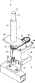
Fig. 1: the front view of the utility model tin soldering machine.
Fig. 2: the lifting of the utility model tin soldering machine and track conveying device stereogram.
Fig. 3: the stereogram of the utility model Traverse Displacement Unit.
Fig. 4: the handstand figure of the utility model Traverse Displacement Unit.
Fig. 5: the three-dimensional exploded view of the utility model Traverse Displacement Unit.
Fig. 6: the generalized section of the utility model Traverse Displacement Unit.
Fig. 7: the port of export stereogram of the utility model tin soldering machine.
Fig. 7-1: the utility model calvus is the stereogram of changing device more.
Fig. 8: the three-dimensional exploded view of the utility model manual hoisting device.
Fig. 9: be the three-dimensional combination figure of Fig. 8 manual hoisting device.
Figure 10: be the full sectional view of Fig. 8 manual hoisting device.
Figure 10-1: be the drive structure enlarged drawing of Figure 10 manual hoisting device.
Figure 11: other plants the three-dimensional exploded view of manual hoisting device the utility model.
Figure 12: be the full sectional view of Figure 11 manual hoisting device.
Figure 12-1: be the drive mechanism enlarged drawing of Figure 12 lowering or hoisting gear.
Figure 13: the three-dimensional exploded view of the utility model Motorized lift device.
Figure 14: be the three-dimensional combination figure of Figure 13 manual hoisting device.
Figure 15: the full sectional view that is the tenth measurements of the chest, waist and hips manual hoisting device.
Figure 16: the lowering or hoisting gear full sectional view of the utility model track centre.
Figure 17: the front end inlet front elevation of the utility model tin soldering machine.
Figure 18: the D structure figure of calvus cleaning device before the utility model two-orbit.
Figure 19: the D structure figure of calvus cleaning device before the utility model two-orbit.
Figure 20: the D structure figure of the utility model calvus cleaning device.
Figure 21: the utility model helps the end view of weld groove and preceding lowering or hoisting gear.
Figure 22: the utility model helps the D structure figure of weld groove.
Figure 23: the full sectional view that helps weld groove for Figure 22.
Fig. 1 is the front view of the utility model tin soldering machine, and casing 10 inside of tin soldering machine shown in the figure are respectively equipped with from front to back and help weld groove 40, heating tank 50 and tin stove 60, and the top of three-flute is provided with oblique delivery track 20.Be provided with telescopic exhaust fume collecting hood 81 in the upper end that helps weld groove 40, be used to absorb the waste gas that helps weld groove to produce; Be provided with exhaust fume collecting hood 82 and in the upper end of tin stove 60 and be engaged on falling of exhaust fume collecting hood side L shaped smoke collection pipe road 83, be used to absorb the pernicious gas that the tin stove produces.
Fig. 2 illustrates the board and the double track conveying device of tin soldering machine, front and back two ends of board 101 respectively are provided with lowering or hoisting gear 1, in addition also be provided with lowering or hoisting gear 1 in central authorities ", only lowering or hoisting gear 1 " be to design at the support of elongated track, if short type track promptly need not to be provided with this lowering or hoisting gear 1 ".Two lowering or hoisting gears, 1 upper end connects U-shaped support 22 in front and back, two secured in parallel framves 21 are set in the support left and right sides, on fixed mount 21, set up one group of track Traverse Displacement Unit 3, this Traverse Displacement Unit comprises: a handwheel 36, one connects the longitudinal rod 37 of handwheel, three commutating tooth wheel seats 363 that are divided into position, connecting rod 37 preceding middle back, three cross bars 31 with the same axle of pinion stand, six support type bearing pedestals 361 that are divided into the cross bar two ends, about these six bearing pedestals are separately fixed on two fixed mounts 21, respectively hang a movable guide block 33 and a fixed guide blocks 34 again on each cross bar 31, can hang track 39 33 times at movable guide block, and at trapped orbit 34 next another tracks 39 ' that hang.
Fig. 3 is the three-dimensional combination figure of cross bar 31 and two guide blocks 33,34, Fig. 4 is that the handstand of Fig. 3 is enclosed, Fig. 5 is the three-dimensional exploded view of Fig. 4, cross bar shown in the figure 31 is hollow circular tubes, two ends are being supported by bearing pedestal 361 (shown in Figure 2), its tube wall has an elongated slot 311 (shown in Figure 3), can penetrate a screw rod 38 (body of rod two ends there is no thread) in the pipe, and the interior umbrella tooth 362 of screw rod one end and pinion stand 363 (shown in Figure 6) combines; Being provided with a bearing holder (housing, cover) 32 in addition in the movable guide block 33 goes into for cross bar 31 pivots, the bottom of this activity guide block also has frame groove 331 and embeds for a clip axletree terminal 30, the clip axletree terminal is fixed in the frame groove after by a bolt 332 packings, and these clip axletree terminal 30 bottoms have the tooth of nibbling, so can be meshing with each other with screw rod 38.Fixed guide blocks 34 is fixed on cross bar 31 end in addition by screw 341 in addition, and it is an irremovable guide block.
Figure 6 shows that the user pass through handwheel 36 (shown in Figure 2) rotate longitudinal rod 37, again pass through before, during and after behind the umbrella tooth 362 of three pinion stands 363, screw rod 38 before, during and after the drive in three cross bars 31, after clip axletree terminal 30 in the movable guide block 33 is driven by screw rod 38, interlock guide block 33 transverse moving left and rights alive.So being set up in three tracks 39 under the movable guide block 33 has synchronous traversing effect, but fixed guide blocks 34 is not fixed by screw 341 again because of establishing the clip axletree terminal, so can not produce traversing effect, so that only need adjusting movable rail 39, the user just can change width between two parallel orbits 39,39 ', to adapt to the circuit board of the big or small width of various differences.
Fig. 7 is the structural map of the tin soldering machine port of export (rear end), and two-orbit shown in the figure 39,39 ' is gone up around chain 391 (Fig. 7-1 has enlarged drawing), is fixing multi-disc metal calvus 392 on the chain, by calvus clipping circuit board.Secondly, be provided with at the end of two-orbit and be horizontally set with a rotating shaft 394 between pinion stand 393, two pinion stands, rotating shaft one end is provided with sprocket wheel 395, and this sprocket wheel can be driven by drive motor 396, after motor starting, drive chain 391 rotations by pinion stand 393, be used for transporting circuit board.In addition, for fear of the two-orbit laying dust, generally all cover with long cover plate 397 in orbit, but the utility model is provided with the liftable protecting cover 398 of an active type (as Fig. 7-1) in long cover panel end, when protecting cover lift open after, the maintenance personal can change the calvus 392 that damages or be out of shape fast, and this is more changing device of calvus of the present utility model.
Fig. 8 is the forward and backward lowering or hoisting gear three-dimensional exploded view of the utility model, and it is a manual lowering or hoisting gear 1, is to be combined by a screwed pipe 12, screw rod 13, base 14, bearing 15, volution 16, axle sleeve 17 and a runner 18; Its combination after structure as shown in Figure 9, complete section is constructed as shown in figure 10.Wherein, screwed pipe 12 is to shuttle back and forth in base 14, after injecting lubricating oil, seals with a dust cover 11 again its top mouth of pipe, the inwall of screwed pipe 12 has internal screw thread 121 and can screw togather mutually with screw rod 13, auspicious on the screwed pipe 12 have an aperture 122, this aperture inserts U-shaped support 22 backs and penetrates by bolt 24 on screwed pipe 12 tops, and makes U-shaped support 22 and screwed pipe 12 secure bond.The following of screw rod 13 has flange 132 as a rotating shaft 131 between rotating shaft and the screw rod again, and the rotating shaft bottom is connecting runner 18.Flange 132 in rotating shaft 131 shown in Figure 10-1 has bearing 15, volution 16, axle sleeve 17, wherein, volution 16 is in the inner bolt hole 142 of solid hollow tube 141 lower ends at base 14 of spiral shell, and axle sleeve 17 is fixed on volution 16 belows by stove bolt 171, makes rotating shaft 131 have the left rotation and right rotation function; Secondly, base 14 is one-body molded by hollow tube 141 and seat board 143, is provided with around the seat board to be fixed on the board 101 after aperture 144 passes for bolt 146 (shown in Figure 8).
After the rotation of operation runner 18, screw rod 13 together rotate, and screwed pipe 12 be produced move radially, when runner 18 when just changeing, screwed pipe 12 risings, otherwise, then descend during counter-rotating; Therefore pass through the rotation liftable U-shaped support 22 of runner 18, to adjust the angle of inclination of track Traverse Displacement Unit 3.In order to adjust and keep in repair the needs of runner 18, the front and back end of board 101 all need be provided with frame groove 26 (shown in Figure 2), and also must be provided with enclosing cover 102 (shown in Figure 7) with respect to casing 10 front and back ends of frame groove 26 in addition.
Figure 11 plants the three-dimensional exploded view of manual hoisting device for other, Figure 12 is the full sectional view of this lowering or hoisting gear, what present embodiment and earlier figures 8 were different is: the bottom of base 14 is circular hole 145 (a non-spiral shell bundle), stay pipe 12 ' (non-screwed pipe) can shuttle back and forth in the base 14, in circular hole 145, be provided with bearing 15 and with big young waiter in a wineshop or an inn's clamp ring 151,152 with its clamping in rotating shaft 131,123 bottoms are provided with swivel nut 19 (Figure 12-1) and the hollow of stay pipe 12 ' is bored a hole, between swivel nut 19 and stay pipe 12 ' by supplying a stove bolt 192 to be screwed into fixing cooperating of half of screw 191,124.Behind operator's rotating wheel 18, can make screw rod 13 rotation, and then drive swivel nut 19 and produce and move radially, swivel nut 19 drives stay pipe 12 ' again and produces lifting action.
Aforementioned two lowering or hoisting gear embodiment are manual manipulation mode, as change Motorized lift device 1 ' enforcement into then shown in Figure 13,14, a motor checkout gear 9 shown in the figure, this device is to give drive sprocket 93 by a motor 91 by reduction box 92 transmissions, and drive sprocket drives another by movable sprocket 95 with chain 94 again, be fixed on by movable sprocket 95 in the rotating shaft 131 of screw rod 13, and rotating shaft 131 bottoms are connected with detector 97 with a hookup 96; Aforementioned motor 91 is fixed on a transverse slat 98 times, and detector 97 is fixed on always on the plate 99, and transverse slat is fastened to each other again with straight plate, and straight plate 99 is fixed on the crossbeam of board.
Shown in Figure 14,15, after operator's starter 91, by its positive and negative direction of rotation of transferring to change Lei bar 13, detector 97 can be measured the rotating cycle of screw rod 13, and by programmable controller set angle so that motor 91 after angle location, stop immediately the action, the great advantage of this mode is that error free generation can be accurately controlled at the angle of inclination of track.
Figure 16 shows that board central authorities lowering or hoisting gear 1 " section enclose, it is fixed on elevating bracket 51, on the board 101 elevating lever 52 that is located in the elevating bracket and sets up tooth bar 521, that hangs down and is fixed in the elevating bracket and is located in the elevating bracket with tooth bar meshed gears 53, one and to be located at elevating bracket outer and combine with the coaxial handwheel 55 of worm screw with the worm screw 54, of gears engaged with latch 531; When the user rotates handwheel 55, drive tooth bar 521 by worm screw 54, gear 53, make elevating lever 52 lifting moving; This device is applicable to the support of elongated fixed mount, but tin soldering machine fixed mount length is not when being not very long, and is then defeasible and do not use; This anti-falling unit 1 " the suitable central part that is supported on fixed mount 21, bear excessive loads and be out of shape to avoid fixed mount central authorities.
Figure 17 is the left side diagrammatic sketch of tin soldering machine, it also is the arrival end front elevation, the front end of two-orbit shown in the figure is provided with two small-sized conveying devices 6 (also can with reference to Figure 18), this device is to drive driving wheel 62 by motor 61, driving wheel drives two followers 64 and two intermediary wheels 65 by belt 63, wherein two followers 64 are and are horizontally disposed with and are divided into machine plate about 66 two ends, and height is contour with the height of calvus 392 clamping circuit boards, so about circuit board PCB places on two belts 63 after, can be before belt be delivered to two-orbit, and then advance by continuing to carry after track calvus 392 clampings of the left and right sides.
Figure 19 shows that the structural map of calvus cleaning device 7 for another example, this device is located at before the two-orbit, its structure as shown in figure 20, wherein a processing solution tank 71 and suction pump 72 are the antethecas that are fixed on casing 10, these processing solution tank 71 bottom surfaces have draining valve 711 and drainage pipe 73, wherein drainage pipe 73 is connected in series with suction pump 72, suction pump 72 through one minute to valve 74 with about two water inlet pipes 75 be connected, two water inlet pipes extend in the wash water groove 76, the wash water groove is fixed on two-orbit 39,39 ' side, contact with calvus with the hairbrush in the groove 77, and the bottom land of wash water groove is directed to processing solution tank 71 with first-class pipe 78 again.Its execution mode after being suction pump 72 startups is extracted processing solution tank 71 liquid medicine out, imports flushing calvus in the wash water groove 76 again through dividing behind valve 74 then, and calvus rubs with hairbrush 77 under chain drives, and the scruff on the calvus is got rid of rapidly, is beneficial to firm clamping circuit board.Liquid medicine in the wash water groove 76 enters in the processing solution tank 71 through stream pipe 78.
Figure 21 helps plane graph after the weld groove improvement for the utility model, help weld groove 40 to be seated on the flat board 41 shown in the figure, this flat board is adjusted screw rod 42 by four and is fixed on the suspension 43, suspension is fixed on preceding U-shaped frame 22 back sides again, Figure 22 illustrates to help and is provided with a foam tank 44 in the weld groove 40, is equipped with a capillary 45 under foam tank, and this capillary is connecting air inlet pipe 46, and foam tank 44 openings are oblique, and are provided with an oblique catch 441 (shown in Figure 23) in the opening; In addition, in the back upper place that helps weld groove 40 one air jet pipe 47 is set, air jet pipe is connecting air inlet pipe 48, and the spray orifice 471 of this pipe can spray oblique gas.Its execution mode is to help must inject in the weld groove 40 to help the welding agent agent, go in the capillary 45 with compressed air then and produce bubble, bubble forms the back and constantly rises in foam tank 44, helping weld groove 40 upper ends to form many foams at last, treat circuit board by help weld groove top by the time can be stained with foam, be infected with too much foam for fear of circuit board bottom surface, can unnecessary foam be removed by air jet pipe 47 oblique ejection gases at high pressure.
It is shown in Figure 2 to return ginseng, be provided with two rail framves 103 shown in the figure in the position of tin stove, on the other board 101 of rail frame, a through hole 104 is set, this through hole also is covered with a loam cake 105, one case groove 106 is set below through hole in addition, the case groove communicates with the case lid 107 (shown in Figure 1) of casing 10, can insert a feeder 108 movably in this case groove.After the operator picks up the scruff in the tin stove, but via through holes 104 pour in the feeder 108 in the case groove 106, treat that feeder collects after to a certain degree, with its taking-up and with offal treatment.
Claims (22)
1, a kind of circuit board soldering tin machine, it is characterized in that: it comprises:
One casing;
One is located at the board in the casing;
One the made circuit board of being located at before the board adheres to the weld groove that helps that helps welding fluid;
One be located at board central authorities can be to the heating tank of circuit board heating, drying;
One is located at the tin stove that made circuit board behind the board attaches tin soldering liquid;
One is located at the lowering or hoisting gear of board front end;
One is located at the lowering or hoisting gear of board rear end;
One is located at the track Traverse Displacement Unit on the front end lowering or hoisting gear;
One is located at the track Traverse Displacement Unit on the lowering or hoisting gear of rear end.
2, circuit board soldering tin machine as claimed in claim 1, it is characterized in that: described lowering or hoisting gear is:
One base is for being fixed on the hollow tube on the board;
One screwed pipe is hubbed in the hollow tube and the top combines with rail bracket, and inside pipe wall has internal screw thread;
One screw rod, the body of rod that is located in the screwed pipe and screws togather with its internal screw thread, it is down as rotating shaft;
One bearing is provided in a side of at the bottom of the hole of hollow tube, and is located in the rotating shaft;
One volution be arranged in the inner bolt hole at the bottom of the hollow pore, and contact bearing;
One manual runner or motor checkout gear is located at the rotating shaft below, and is located at the inner covert of board, makes the screw rod rotation by manual or motor transmission;
By by combinations thereof, make the screw rod rotation with manual rotation or with the motor transmission, and drive screwed pipe and produce radially lifting, make also together lifting and change the angle of inclination of two tracks of track.
3, circuit board soldering tin machine as claimed in claim 2 is characterized in that: described screwed pipe top is provided with a capping.
4, circuit board soldering tin machine as claimed in claim 2 is characterized in that: can encircle in the described rotating shaft and establish axle sleeve, described axle sleeve is adjacent to the below of volution.
5, circuit board soldering tin machine as claimed in claim 2 is characterized in that: described motor checkout gear is fixed on the motor under the transverse slat, gives sprocket wheel by the reduction box transmission, drives another sprocket wheel by sprocket wheel with chain again, and this is fixed in the rotating shaft by movable sprocket.
6, circuit board soldering tin machine as claimed in claim 5 is characterized in that: described rotating shaft bottom links to each other with detector with hookup, and detector is fixed on the straight plate, and described straight plate and transverse slat interfix.
7, circuit board soldering tin machine as claimed in claim 1, it is characterized in that: described lowering or hoisting gear is:
One base is fixed on the hollow tube on the board;
One stay pipe is hubbed on the body in the hollow tube, and its top combines with rail bracket;
One screw rod is located in the stay pipe, and down as rotating shaft;
One swivel nut is arranged on the screw rod, and gives secure bond with bolt between stay pipe:
One bearing is located at the bottom of the hole of hollow tube, and is located on to change and draws up:
One little clamp ring is folded in to head in the rotating shaft to take out and holds;
One big clamp ring is folded at the bottom of the hole of hollow tube to take out with contact and holds:
One manual runner or motor checkout gear is located at the rotating shaft below, and all is located at board inside under cover, makes the screw rod rotation by manual or motor transmission; By above-mentioned combination, make screw rod rotation back drive swivel nut with manual rotating wheel or with the motor transmission, and by swivel nut and stay pipe radially lifting synchronously, make also together lifting and change the luffing angle of two tracks of rail bracket.
8, circuit board soldering tin machine as claimed in claim 7 is characterized in that: described screwed pipe top is provided with capping sealing.
9, circuit board soldering tin machine as claimed in claim 7 is characterized in that: described motor checkout gear comprises that one is fixed on the motor under the transverse slat, gives sprocket wheel by the reduction box transmission, drives another sprocket wheel by sprocket wheel with chain again, and this is fixed in the rotating shaft by movable sprocket.
10, circuit board soldering tin machine as claimed in claim 9 is characterized in that: described rotating shaft bottom links to each other with a hookup, detector, and detector is fixed on the straight plate, and described straight plate and transverse slat interfix.
11, circuit board soldering tin machine as claimed in claim 1 is characterized in that: the board of described tin soldering machine:
One through hole is set on the board table top, has one case groove at through hole, can insert a movable feeder in the case groove, and case groove and the case lid of casing side be symmetry and cooperate, described feeder can be used for collecting the interior scruff that is produced of solder furnace.
12, circuit board soldering tin machine as claimed in claim 11, it is characterized in that: described through hole is covered with a loam cake.
13, circuit board soldering tin machine as claimed in claim 1 is characterized in that: the described weld groove that helps is:
Help and be provided with a foam tank in the weld groove, be equipped with a long capillary under foam tank, described capillary is connecting air inlet pipe; In the back upper place that helps weld groove one air jet pipe is set, air jet pipe is connecting air inlet pipe, and the spray orifice of described air jet pipe can oblique ejection gas.
14, circuit board soldering tin machine as claimed in claim 13, it is characterized in that: the opening of described foam tank is oblique, and is provided with an oblique catch in the opening.
15, circuit board soldering tin machine as claimed in claim 1 is characterized in that: the track front end of described tin soldering machine is provided with the calvus cleaning device, and this device is:
One is fixed on the processing solution tank and the suction pump of casing antetheca, described processing solution tank bottom surface has draining valve and drainage pipe, described drainage pipe is connected in series with suction pump, suction pump through one minute to valve with about two water inlet pipes be connected, two water inlet pipes extend in the wash water groove, the wash water groove is fixed on the side of two-orbit, and the hairbrush in its groove contacts with the chain calvus, and the bottom land of wash water groove is directed to processing solution tank with first-class pipe again.
16, circuit board soldering tin machine as claimed in claim 1 is characterized in that: described track Traverse Displacement Unit is:
Two lowering or hoisting gears upper end connects the U-shaped support in front and back, two secured in parallel framves are set in the support left and right sides, on fixed mount, set up one group of track Traverse Displacement Unit, this Traverse Displacement Unit comprises: a handwheel, one connects the longitudinal rod of handwheel, two commutating tooth wheel seats that are divided into position, the preceding middle back of connecting rod, two cross bars with the same axle of pinion stand, four support type bearing pedestals that are divided into the cross bar two ends, about described four bearing pedestals are separately fixed on two fixed mounts, hang a movable guide block and a fixed guide blocks on each cross bar, under movable guide block, can hang track, under trapped orbit, hang another track.
17, circuit board soldering tin machine as claimed in claim 16, it is characterized in that: the central part of described support two-orbit, can be about the two-orbit central part be set up two lowering or hoisting gears, this device is fixed in the elevating bracket and is located in the elevating bracket with tooth bar meshed gears, one and to be located at elevating bracket outer and combine with the coaxial handwheel of worm screw with the worm screw, of gears engaged with latch for being fixed on elevating bracket, on the board elevating lever that is located in the elevating bracket and sets up tooth bar, that hangs down.
18, circuit board soldering tin machine as claimed in claim 17, it is characterized in that: set up in left and right sides fixed mount central authorities and take out bearing, one cross bar is set between two bearing bracket, cross bar one end connects a commutating tooth wheel seat that combines with connecting rod, hang a movable guide block and a fixed guide blocks on the cross bar, each is connected two guide blocks with track.
19, as claim 16 or 18 described circuit board soldering tin machines, it is characterized in that: described cross bar is a hollow circular tube, and tube wall has an elongated slot, can penetrate a screw rod in the pipe, and the interior umbrella tooth of screw rod one end and pinion stand combines; Be provided with the bearing holder (housing, cover) that can go into for the cross bar pivot in the movable guide block, the bottom of this activity guide block also has the frame groove that embeds for a clip axletree terminal, and the clip axletree terminal is fixed in the frame groove after by a bolt packing, and this clip axletree terminal bottom has the tooth of nibbling, and is meshing with each other with screw rod; Other fixed guide blocks is fixed on cross bar by screw, and other is auspicious, and it is an irremovable guide block.
20, circuit board soldering tin machine as claimed in claim 16 is characterized in that: cover the long cover plate of one deck on two-orbit, the liftable protecting cover of an active type is set endways.
21, circuit board soldering tin machine as claimed in claim 16, it is characterized in that: the front end of described two-orbit is provided with two small-sized conveying devices, this device is to drive driving wheel by motor, driving wheel drives two followers and two intermediary wheels by belt, wherein two followers be horizontally disposed with and be divided into the machine plate about two ends, and the height contour with the height of calvus clamping circuit board.
22, circuit board soldering tin machine as claimed in claim 16 is characterized in that: the front end at casing is provided with telescopic exhaust fume collecting hood, is provided with one at the exhaust fume collecting hood side of casing rear end and falls L shaped smoke collection pipe road.
Priority Applications (1)
| Application Number | Priority Date | Filing Date | Title |
|---|---|---|---|
| CN 01224754 CN2481113Y (en) | 2001-05-28 | 2001-05-28 | Tin-soldering machine for electric circuit board |
Applications Claiming Priority (1)
| Application Number | Priority Date | Filing Date | Title |
|---|---|---|---|
| CN 01224754 CN2481113Y (en) | 2001-05-28 | 2001-05-28 | Tin-soldering machine for electric circuit board |
Publications (1)
| Publication Number | Publication Date |
|---|---|
| CN2481113Y true CN2481113Y (en) | 2002-03-06 |
Family
ID=33640984
Family Applications (1)
| Application Number | Title | Priority Date | Filing Date |
|---|---|---|---|
| CN 01224754 Expired - Fee Related CN2481113Y (en) | 2001-05-28 | 2001-05-28 | Tin-soldering machine for electric circuit board |
Country Status (1)
| Country | Link |
|---|---|
| CN (1) | CN2481113Y (en) |
Cited By (7)
| Publication number | Priority date | Publication date | Assignee | Title |
|---|---|---|---|---|
| CN102489421A (en) * | 2011-10-17 | 2012-06-13 | 杜星光 | Selective spraying machine |
| US9259794B2 (en) | 2012-11-12 | 2016-02-16 | Delta Electronics Power(Dong Guan)Co., Ltd. | Flux spray machine |
| CN105413932A (en) * | 2015-12-23 | 2016-03-23 | 苏州智强嘉智自动化科技有限公司 | Automatic surface coating equipment |
| CN105772288A (en) * | 2016-03-24 | 2016-07-20 | 魏会芳 | Large-batch steel paint spraying integrated machine |
| CN106975817A (en) * | 2017-05-03 | 2017-07-25 | 慈溪智江机械科技有限公司 | A kind of tin-soldering machine for electric circuit board |
| CN107902325A (en) * | 2017-12-07 | 2018-04-13 | 江苏凯尔生物识别科技有限公司 | Pcb board production bearing device |
| CN114141158A (en) * | 2021-11-08 | 2022-03-04 | 星源电子科技(深圳)有限公司 | Micro-LED backplate patching device convenient to operation is used |
-
2001
- 2001-05-28 CN CN 01224754 patent/CN2481113Y/en not_active Expired - Fee Related
Cited By (9)
| Publication number | Priority date | Publication date | Assignee | Title |
|---|---|---|---|---|
| CN102489421A (en) * | 2011-10-17 | 2012-06-13 | 杜星光 | Selective spraying machine |
| US9259794B2 (en) | 2012-11-12 | 2016-02-16 | Delta Electronics Power(Dong Guan)Co., Ltd. | Flux spray machine |
| CN105413932A (en) * | 2015-12-23 | 2016-03-23 | 苏州智强嘉智自动化科技有限公司 | Automatic surface coating equipment |
| CN105772288A (en) * | 2016-03-24 | 2016-07-20 | 魏会芳 | Large-batch steel paint spraying integrated machine |
| CN105772288B (en) * | 2016-03-24 | 2017-12-26 | 江苏万年达杭萧钢构有限公司 | A kind of high-volume steel spray painting all-in-one |
| CN106975817A (en) * | 2017-05-03 | 2017-07-25 | 慈溪智江机械科技有限公司 | A kind of tin-soldering machine for electric circuit board |
| CN107902325A (en) * | 2017-12-07 | 2018-04-13 | 江苏凯尔生物识别科技有限公司 | Pcb board production bearing device |
| CN107902325B (en) * | 2017-12-07 | 2024-03-29 | 江苏凯尔生物识别科技有限公司 | Supporting device for PCB production |
| CN114141158A (en) * | 2021-11-08 | 2022-03-04 | 星源电子科技(深圳)有限公司 | Micro-LED backplate patching device convenient to operation is used |
Similar Documents
| Publication | Publication Date | Title |
|---|---|---|
| CN208527501U (en) | A kind of full-automatic oil injector body cleaning machine | |
| CN209791105U (en) | Pulse dust collector | |
| CN2481113Y (en) | Tin-soldering machine for electric circuit board | |
| CN110433639A (en) | Waste material recovery device is used in a kind of processing of detergent | |
| CN113578611B (en) | Pump body surface paint spraying apparatus | |
| CN214441250U (en) | SMT steel mesh belt cleaning device | |
| CN113275810A (en) | Welding device for machining container beam assembly of van | |
| CN112495881A (en) | Table top scrap cleaning device for production and processing of forged parts | |
| CN108392916A (en) | A kind of chemical plant waste gas treatment equipment | |
| CN205851469U (en) | Mixed flow cleaning machine | |
| CN215610390U (en) | PCB welding waste gas absorption device for spring reset during compression | |
| CN203061523U (en) | Full-automatic cylinder barrel cleaning machine | |
| CN113102373B (en) | Ultrasonic cleaner system | |
| CN109465128A (en) | A kind of energy-saving and high efficient paint spraying apparatus | |
| CN113020849A (en) | Environment-friendly motorcycle front fork pipe welding set based on intelligent manufacturing | |
| CN116572063A (en) | Cutting device with collection function for processing civil air defense door and working method thereof | |
| CN216087148U (en) | Surface treatment device for printed circuit board | |
| CN115465629A (en) | Food frying hanging basket and hanging basket type food frying device | |
| CN110416402A (en) | A kind of automatic silver paste printing machine | |
| CN216404002U (en) | Multistage filter equipment for industrial water treatment | |
| CN115518802A (en) | Water curtain type water-spinning paint spray booth and use method thereof | |
| CN113102374B (en) | Push type ultrasonic cleaner, cleaning method and cleaning system thereof | |
| CN114669147A (en) | Building construction site dust collector | |
| CN212792335U (en) | Dust collector for machining | |
| CN109226115B (en) | Vertical deep hole saturated steam cleaning machine |
Legal Events
| Date | Code | Title | Description |
|---|---|---|---|
| C14 | Grant of patent or utility model | ||
| GR01 | Patent grant | ||
| C19 | Lapse of patent right due to non-payment of the annual fee | ||
| CF01 | Termination of patent right due to non-payment of annual fee |